US18543A - Smoothing-iron - Google Patents
Smoothing-iron Download PDFInfo
- Publication number
- US18543A US18543A US18543DA US18543A US 18543 A US18543 A US 18543A US 18543D A US18543D A US 18543DA US 18543 A US18543 A US 18543A
- Authority
- US
- United States
- Prior art keywords
- iron
- gas
- heat
- smoothing
- plate
- Prior art date
- Legal status (The legal status is an assumption and is not a legal conclusion. Google has not performed a legal analysis and makes no representation as to the accuracy of the status listed.)
- Expired - Lifetime
Links
- XEEYBQQBJWHFJM-UHFFFAOYSA-N iron Substances [Fe] XEEYBQQBJWHFJM-UHFFFAOYSA-N 0.000 title description 67
- 229910052742 iron Inorganic materials 0.000 title description 34
- 238000010438 heat treatment Methods 0.000 description 4
- XLYOFNOQVPJJNP-UHFFFAOYSA-N water Substances O XLYOFNOQVPJJNP-UHFFFAOYSA-N 0.000 description 3
- 239000003610 charcoal Substances 0.000 description 2
- 235000000396 iron Nutrition 0.000 description 2
- 238000009835 boiling Methods 0.000 description 1
- 238000002485 combustion reaction Methods 0.000 description 1
- 238000010276 construction Methods 0.000 description 1
- 238000009499 grossing Methods 0.000 description 1
- 239000008236 heating water Substances 0.000 description 1
- 238000010409 ironing Methods 0.000 description 1
- 238000000034 method Methods 0.000 description 1
- 230000000717 retained effect Effects 0.000 description 1
- 230000000979 retarding effect Effects 0.000 description 1
- 239000000779 smoke Substances 0.000 description 1
Images
Classifications
-
- D—TEXTILES; PAPER
- D06—TREATMENT OF TEXTILES OR THE LIKE; LAUNDERING; FLEXIBLE MATERIALS NOT OTHERWISE PROVIDED FOR
- D06F—LAUNDERING, DRYING, IRONING, PRESSING OR FOLDING TEXTILE ARTICLES
- D06F75/00—Hand irons
- D06F75/02—Externally-heated hand irons; Hand irons internally heated by means other than electricity, e.g. by solid fuel, by steam
Definitions
- myimprovement consists in the arrangement of the different portions together employed for heating the iron by which I am enabled to distribute and retain the heat in the bottom of the iron and keep it sufficient hot during the time lof ironing without stopping to heat the iron as is commonly the case with all ordinary methods of heating irons for smoothing purposes with charcoal or gas.
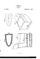
- FIG. 2 represents a longitudinal sectional elevation of the improved iron.
- Fig. 2 is a horizontal sectional view of the same.
- Fig. 3 is a perforated diaphragm placed in the iron and employed to help retain the most of the heat in the iron and assist in distributing it over the lower surface of the iron.
- Fig. 4 is a perspective view of the iron with the top and handle of it removed and furnished with an opened plate for boiling water and similar purposes with the gas if desired.
- A is the iron made of an ordinary form and hollow and B, B, is a gas pipe bent and formed to suit the shape of the bottom of the iron around its edges and back part and perforated With openings for the escape of the gas against the sides and end of the iron-for, if the gas was allowed to strike against the bottom. of the iron it would smoke and heat in spots where the jet of gas would strike and if allowed to escape from the top of the pipe B, the heat would have a tendency of rushing out of the iron through the chimney. But when made to escape at the side of the pipe B, against the side of the iron the difficulties before stated are more or less obviated by retaining the heat and cause it more equally to distribute itself over the iron.
- the gas is let into the pipe B, B, with a fleXble tube connected to the iron at the joint piece d and f.
- C, C is a wire gauze placed around the pipe B, in the iron for distributing the gas evenly over the surface of the iron as much as possible.
- g, g is a perforated plate set in at the top of the iron about one third of the depth of the iron from its top for helping in retaining and distributing the heat over the surface of it by retarding the escape of the heat into the chimney p is the top of the iron furnished with a handle la and chimney pipe (i) and is held to its place by a rod passing through the lugs J, attached to the iron and its top.
- 10, 10, Fig. 4 is a plate placed on the top of the iron when the handle is removed, and furnished with an opening 8, for placing a vessel of water on to be heated by the gas and 9 is another opening in the plate to give a draft, and when the gas in the iron is being used for heating water and similar purposes the plate g, g, in the iron Will be removed in such cases so as to give the heat a better chance to act on the vessel containing the Water.
- Vhat I do claim as my improvement and desire to secure by Letters Patent is- 'Ihe arrangement of the perforated diaphragm g, g, With the air openings 5, 5, and
Landscapes
- Engineering & Computer Science (AREA)
- Textile Engineering (AREA)
- Irons (AREA)
Description
J. GOODIN, Jr. Sad Iron.
N0.18,543. Y Patented Nov. 3.1857.
N. PETERS. Pham-ummm". wmhingwn n. c.
JAMES GOODIN,JR `OF CINCINNATI, OHIO.
SMOOTHING-IRON.
Specicaton of Letters Patent No. 18,543, dated November 3, 1857.
lb all whom it mag/,concam:
Be it known that I, JAMES GooDIN,`Jr., of the city of Cincinnati, county offI-Iamilton, and State of Ohio, haveA invented a new and useful Improvement in Smoothing-Irons; and I do hereby declare that the following is a full and eXact description thereof, reference being had to the accompanying drawings and made to form part of this specication and to the letters of reference marked thereon.
Similar letters refer to'like parts of the improvement.
The nature of myimprovement consists in the arrangement of the different portions together employed for heating the iron by which I am enabled to distribute and retain the heat in the bottom of the iron and keep it sufficient hot during the time lof ironing without stopping to heat the iron as is commonly the case with all ordinary methods of heating irons for smoothing purposes with charcoal or gas.
To enable others skilled in the art to make and use my improvement I will proceed to describe its construction and operation by referring direct to the accompanying drawing of whichl Figure l, represents a longitudinal sectional elevation of the improved iron. Fig. 2, is a horizontal sectional view of the same. Fig. 3, is a perforated diaphragm placed in the iron and employed to help retain the most of the heat in the iron and assist in distributing it over the lower surface of the iron. Fig. 4, is a perspective view of the iron with the top and handle of it removed and furnished with an opened plate for boiling water and similar purposes with the gas if desired.
A is the iron made of an ordinary form and hollow and B, B, is a gas pipe bent and formed to suit the shape of the bottom of the iron around its edges and back part and perforated With openings for the escape of the gas against the sides and end of the iron-for, if the gas was allowed to strike against the bottom. of the iron it would smoke and heat in spots where the jet of gas would strike and if allowed to escape from the top of the pipe B, the heat would have a tendency of rushing out of the iron through the chimney. But when made to escape at the side of the pipe B, against the side of the iron the difficulties before stated are more or less obviated by retaining the heat and cause it more equally to distribute itself over the iron.
The gas is let into the pipe B, B, with a fleXble tube connected to the iron at the joint piece d and f.
C, C, is a wire gauze placed around the pipe B, in the iron for distributing the gas evenly over the surface of the iron as much as possible.
g, g, is a perforated plate set in at the top of the iron about one third of the depth of the iron from its top for helping in retaining and distributing the heat over the surface of it by retarding the escape of the heat into the chimney p is the top of the iron furnished with a handle la and chimney pipe (i) and is held to its place by a rod passing through the lugs J, attached to the iron and its top.
5, 5, 5, and 7, 7, 7, 7, are air openings for supplying the gas with air for combustion and assist in distributing the heat equally over the surface of the iron. The combined use of the air holes 5 and 7 with the plate g, g, serve to equally distribute and retain the heat over the surface of the bottom of the iron by the following action of the air and use of the plate: When gas is admitted to the inside of the iron and ignited by air passing in the openings 5, 5, if it was not for the air openings 7 7 on each side of the iron the heat of the gas and flame would have a tendency of rushing to the chimney and pass off without heating the iron but with the use of the air openings 7, 7, air is admitted to the top of the flame which retains and distributes it and the heat--with the help of the plate g, g, over the surface of the bottom of the iron, and thus by the arrangement of the air openings 5, and 7 and plate g, g, with the gas apparatus B in the bottom of the iron the heat is retained and distributed evenly over the bottom of the iron-suiiicient at all times to keep it hot enough to iron with without being necessary for the operator to stop work for the iron to heat, as is commonly the case when irons have been heated with charcoal or gas.
10, 10, Fig. 4, is a plate placed on the top of the iron when the handle is removed, and furnished with an opening 8, for placing a vessel of water on to be heated by the gas and 9 is another opening in the plate to give a draft, and when the gas in the iron is being used for heating water and similar purposes the plate g, g, in the iron Will be removed in such cases so as to give the heat a better chance to act on the vessel containing the Water.
I am aware of gas having been used for heating purposes before and that Wire gauze has been employed for distributing the heat all of which I disclaim When taken separately or together. But
Vhat I do claim as my improvement and desire to secure by Letters Patent is- 'Ihe arrangement of the perforated diaphragm g, g, With the air openings 5, 5, and
Publications (1)
| Publication Number | Publication Date |
|---|---|
| US18543A true US18543A (en) | 1857-11-03 |
Family
ID=2081947
Family Applications (1)
| Application Number | Title | Priority Date | Filing Date |
|---|---|---|---|
| US18543D Expired - Lifetime US18543A (en) | Smoothing-iron |
Country Status (1)
| Country | Link |
|---|---|
| US (1) | US18543A (en) |
-
0
- US US18543D patent/US18543A/en not_active Expired - Lifetime
Similar Documents
| Publication | Publication Date | Title |
|---|---|---|
| US18543A (en) | Smoothing-iron | |
| US9241A (en) | Smoothing-iron | |
| US28546A (en) | andrews | |
| US1201905A (en) | Heater for sad-irons. | |
| US29376A (en) | Apparatus for boiling and distilling | |
| US13743A (en) | Method of treating- air for blast-furnaces | |
| US21891A (en) | Flat-iron | |
| US14796A (en) | Self-heatinor smoothing-irow | |
| US17578A (en) | Toot-stove | |
| US1780236A (en) | Self-steaming iron | |
| US24667A (en) | Ironing-pan for ranges or stoves | |
| US15165A (en) | Smoothihg-irou | |
| US1205272A (en) | Heater for curling-irons. | |
| US10686A (en) | Eotary smoothing-iron | |
| US69347A (en) | Improved sad-iron heater | |
| US81644A (en) | Improvement in tinners fire-pots | |
| US5971A (en) | Samuel maxam | |
| US44166A (en) | James david | |
| US171444A (en) | Improvenient in steam candy-heaters | |
| US369830A (en) | Smoothing-iron | |
| US212363A (en) | Improvement in sad-iron holders | |
| US513530A (en) | george e | |
| US10409A (en) | Sele-heatibtg smoothing-ikon | |
| US390478A (en) | Flat-iron heater | |
| US11259A (en) | Andrew mayer |