US18542A - Machine for bending metal blates - Google Patents
Machine for bending metal blates Download PDFInfo
- Publication number
- US18542A US18542A US18542DA US18542A US 18542 A US18542 A US 18542A US 18542D A US18542D A US 18542DA US 18542 A US18542 A US 18542A
- Authority
- US
- United States
- Prior art keywords
- block
- machine
- blates
- box
- plate
- Prior art date
- Legal status (The legal status is an assumption and is not a legal conclusion. Google has not performed a legal analysis and makes no representation as to the accuracy of the status listed.)
- Expired - Lifetime
Links
- 239000002184 metal Substances 0.000 title description 5
- 238000005452 bending Methods 0.000 title description 3
- 229910000831 Steel Inorganic materials 0.000 description 3
- 239000010959 steel Substances 0.000 description 3
- 210000000038 chest Anatomy 0.000 description 1
Images
Classifications
-
- B—PERFORMING OPERATIONS; TRANSPORTING
- B25—HAND TOOLS; PORTABLE POWER-DRIVEN TOOLS; MANIPULATORS
- B25B—TOOLS OR BENCH DEVICES NOT OTHERWISE PROVIDED FOR, FOR FASTENING, CONNECTING, DISENGAGING OR HOLDING
- B25B1/00—Vices
- B25B1/06—Arrangements for positively actuating jaws
- B25B1/10—Arrangements for positively actuating jaws using screws
- B25B1/103—Arrangements for positively actuating jaws using screws with one screw perpendicular to the jaw faces, e.g. a differential or telescopic screw
Definitions
- the object of this invention is to bend at one operation metal plates in sharp angular form to answer the purpose of lock cases or plates for such locks as are used for drawers chests &c, in which a single bent plate is employed.
- the invention consists in the employment or use of a clamp, bed piece and adjustable stop, arranged as hereinafter shown, by which in connection with a drop or an equivalent device the desired work is performed in an expeditious and perfect manner.
- A represents a square metal block in the upper part of which a rectangular metal box B, is rmly keyed. IVithin the box B a rectangular steel block C is placed, said block having the inner end of a screw I) lit-ted in it, the screw passing through the end of the box B tting in an internal thread and having a crank E attached to its outer end. By turning the crank E the block C may be moved back and forth within the box B.
- a shaft F passes, the shaft also passing through oblong slots in the sides of the box B.
- the shaft F has a crank Gr on one end at the outer side of the box B, and two arms (a) (a) are secured to said shaft, the arms being one at each side of the block C and fitted in recesses made to receive ⁇ them.
- a cross piece (Z9) is secured and a recess (c) is made in the outer Side of the crosspiece to receive one end of the plate as will be presently described.
- the block H is a rectangular steel block which is tted within the box B.
- the upper surface of the block H is flush with the upper surface of the block C, and is of such a length as to allow a certain degree of movement to the block C.
- the block H may be termed a bed block or bedpiece.
- I represents a rectangular steel block which rests upon the block or bedpiece H and is attached to the inner end of a slide rod (d) which passes through one end of box B.
- the set screws (e) (e) also pass through the same end of the box and serve as bearers to the block I.
- the rod (d) may be secured at any desired point by means of a screw (f) which pass vertically into the end of the box B and bears upon said rod as shown clearly in Fig. 1.
- each side of the block A an upright .l is secured, and the upper ends of the uprights are connected by a cross-tie (g).
- K is a drop which is fitted and slides between the uprights J, J.
- the drop K is arranged in the usual way and therefore it does not require a minute description.
- the operation is as follows-The plates L are cut of the proper size and are bent as follows. One end of a plate L is placed within the recess (c) as shown in black Fig. 2, and the block C is then moved forward by turning the screw E until the lower end of plate L is secured or clamped between the crosspiece (b) and the block H. The upper part of plate L is then bent over a trifle as shown by the dotted lines Fig. l, and the drop K is then allowed to descend, the drop bending the upper plate flat upon the upper surface of the block or bed-pieceV H.
- the block I serves as a stop and prevents the plate from Abeing expanded too much in a longitudinal direction.
- the angle as shown at (g) is brought up perfectly sharp, as the expansion of the plate is controlled or stopped at one end by the stop I the plate therefore will be in a measure upset and spread toward said angle so as to make its edge perfectly sharp or full.
- the drop is raised the block C moved back and the cross piece (b) raised by turning the crank Gr so that the bent plate may be removed.
- stopI is broadly a drop press nor any of the parts Y herein described separately; but
- the block C provided with the movable arms (a) (a) and cross piece (b) the block or bed piece I-I and adjustable stop I arranged as shown and used in connection with a drop K or its equivalent for the purl pose set forth.
Landscapes
- Engineering & Computer Science (AREA)
- Mechanical Engineering (AREA)
- Bending Of Plates, Rods, And Pipes (AREA)
Description
fi Z. wfg/mf) PHON-LITHOGRAPHER, WASHINGTON. D l?.
UNITED sTATEs PATENT oEEIcE.
E. L. GAYLORD, OF TERRYVILLE, CONNECTICUT.
MACHINE FOR IBENIDING METAL PLATES.
, Specification of Letters Patent N o. 18,542, dated November 3, 1857.
To all 'whom t may concern:
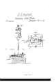
Be it known that I, E. L. GAYLORD, of Terryville, in the county of Litcheld and State of Connecticut, have invented a new and Improved Machine for Bending Metal Plates for Lock Cases or Plates and Similar or Analogous Purposes; and I do hereby declare that the following is a full, clear, and exact description of the same, reference being had to the annexed drawings, making a part of this specification, in which- Figure l, is a side sectional elevation of my improvement, taken in the line Fig. 2. Fig. 2 is a horizontal section of ditto taken in the line Fig. 1.
Similar letters of reference indicate corresponding parts in the two figures.
The object of this invention is to bend at one operation metal plates in sharp angular form to answer the purpose of lock cases or plates for such locks as are used for drawers chests &c, in which a single bent plate is employed.
The invention consists in the employment or use of a clamp, bed piece and adjustable stop, arranged as hereinafter shown, by which in connection with a drop or an equivalent device the desired work is performed in an expeditious and perfect manner.
To enable those skilled in the art to fully understand and construct my invention I will proceed to describe it. e y
A represents a square metal block in the upper part of which a rectangular metal box B, is rmly keyed. IVithin the box B a rectangular steel block C is placed, said block having the inner end of a screw I) lit-ted in it, the screw passing through the end of the box B tting in an internal thread and having a crank E attached to its outer end. By turning the crank E the block C may be moved back and forth within the box B.
Transversely through the block C a shaft F passes, the shaft also passing through oblong slots in the sides of the box B. The shaft F has a crank Gr on one end at the outer side of the box B, and two arms (a) (a) are secured to said shaft, the arms being one at each side of the block C and fitted in recesses made to receive` them. To the outer ends of the arms (a) (a) a cross piece (Z9) is secured and a recess (c) is made in the outer Side of the crosspiece to receive one end of the plate as will be presently described.
H is a rectangular steel block which is tted within the box B. The upper surface of the block H is flush with the upper surface of the block C, and is of such a length as to allow a certain degree of movement to the block C. The block H may be termed a bed block or bedpiece.
I represents a rectangular steel block which rests upon the block or bedpiece H and is attached to the inner end of a slide rod (d) which passes through one end of box B. The set screws (e) (e) also pass through the same end of the box and serve as bearers to the block I. The rod (d) may be secured at any desired point by means of a screw (f) which pass vertically into the end of the box B and bears upon said rod as shown clearly in Fig. 1.
'Io each side of the block A an upright .l is secured, and the upper ends of the uprights are connected by a cross-tie (g).
K is a drop which is fitted and slides between the uprights J, J. The drop K is arranged in the usual way and therefore it does not require a minute description.
The operation is as follows-The plates L are cut of the proper size and are bent as follows. One end of a plate L is placed within the recess (c) as shown in black Fig. 2, and the block C is then moved forward by turning the screw E until the lower end of plate L is secured or clamped between the crosspiece (b) and the block H. The upper part of plate L is then bent over a trifle as shown by the dotted lines Fig. l, and the drop K is then allowed to descend, the drop bending the upper plate flat upon the upper surface of the block or bed-pieceV H. The block I, serves as a stop and prevents the plate from Abeing expanded too much in a longitudinal direction. By this means the angle as shown at (g) is brought up perfectly sharp, as the expansion of the plate is controlled or stopped at one end by the stop I the plate therefore will be in a measure upset and spread toward said angle so as to make its edge perfectly sharp or full. When the plate Lis bent, the drop is raised the block C moved back and the cross piece (b) raised by turning the crank Gr so that the bent plate may be removed.
It will be understood that the stopI is broadly a drop press nor any of the parts Y herein described separately; but
Having thus described my invention what I claim as new and desire to secure by Letters Patent, is,
The block C provided with the movable arms (a) (a) and cross piece (b) the block or bed piece I-I and adjustable stop I arranged as shown and used in connection with a drop K or its equivalent for the purl pose set forth.
E. L. GAYLORD. Witnesses:
GEO. B. HEMPSTED, B. I-I. I-IEMINGWAY.
Publications (1)
| Publication Number | Publication Date |
|---|---|
| US18542A true US18542A (en) | 1857-11-03 |
Family
ID=2081945
Family Applications (1)
| Application Number | Title | Priority Date | Filing Date |
|---|---|---|---|
| US18542D Expired - Lifetime US18542A (en) | Machine for bending metal blates |
Country Status (1)
| Country | Link |
|---|---|
| US (1) | US18542A (en) |
-
0
- US US18542D patent/US18542A/en not_active Expired - Lifetime
Similar Documents
| Publication | Publication Date | Title |
|---|---|---|
| US16228A (en) | Spring-bolt | |
| US13570A (en) | Cutting- wir-e | |
| US18542A (en) | Machine for bending metal blates | |
| US13670A (en) | Gage attachment for sawistg-machiktes | |
| US26553A (en) | The graphic co | |
| US6817A (en) | Circular-saw set | |
| US16456A (en) | Improved machine for bending sheet metal | |
| US71259A (en) | Josiah ye a gee | |
| US13237A (en) | Gage for stair-bails | |
| US13357A (en) | Circular-saw mandrel | |
| US12917A (en) | Tool fob | |
| US629862A (en) | Punching-machine. | |
| US29623A (en) | Wrench ajstd vise | |
| US12916A (en) | Tool for | |
| US81476A (en) | Improvement in cutting printers leads | |
| US13945A (en) | Improvement in spike-machines | |
| US14390A (en) | Bench-clamp | |
| US17178A (en) | Railroad-chair machine | |
| US49638A (en) | Improved bolt-machine | |
| US14866A (en) | Edward heath | |
| US17219A (en) | Adjustable bed and gage to regulate tenoning | |
| US18019A (en) | Machine fob bending metal plates | |
| US15119A (en) | Saw-set | |
| US18011A (en) | Machine for | |
| US9385A (en) | Turning-jaw vise |