US1854085A - Compressor valve unit - Google Patents
Compressor valve unit Download PDFInfo
- Publication number
- US1854085A US1854085A US447315A US44731530A US1854085A US 1854085 A US1854085 A US 1854085A US 447315 A US447315 A US 447315A US 44731530 A US44731530 A US 44731530A US 1854085 A US1854085 A US 1854085A
- Authority
- US
- United States
- Prior art keywords
- valve
- ports
- compressor
- retainers
- head
- Prior art date
- Legal status (The legal status is an assumption and is not a legal conclusion. Google has not performed a legal analysis and makes no representation as to the accuracy of the status listed.)
- Expired - Lifetime
Links
- XLYOFNOQVPJJNP-UHFFFAOYSA-N water Substances O XLYOFNOQVPJJNP-UHFFFAOYSA-N 0.000 description 5
- 239000007787 solid Substances 0.000 description 4
- 238000010276 construction Methods 0.000 description 3
- 238000001816 cooling Methods 0.000 description 1
Images

Classifications
-
- F—MECHANICAL ENGINEERING; LIGHTING; HEATING; WEAPONS; BLASTING
- F04—POSITIVE - DISPLACEMENT MACHINES FOR LIQUIDS; PUMPS FOR LIQUIDS OR ELASTIC FLUIDS
- F04B—POSITIVE-DISPLACEMENT MACHINES FOR LIQUIDS; PUMPS
- F04B49/00—Control, e.g. of pump delivery, or pump pressure of, or safety measures for, machines, pumps, or pumping installations, not otherwise provided for, or of interest apart from, groups F04B1/00 - F04B47/00
- F04B49/22—Control, e.g. of pump delivery, or pump pressure of, or safety measures for, machines, pumps, or pumping installations, not otherwise provided for, or of interest apart from, groups F04B1/00 - F04B47/00 by means of valves
- F04B49/24—Bypassing
- F04B49/243—Bypassing by keeping open the inlet valve
-
- F—MECHANICAL ENGINEERING; LIGHTING; HEATING; WEAPONS; BLASTING
- F04—POSITIVE - DISPLACEMENT MACHINES FOR LIQUIDS; PUMPS FOR LIQUIDS OR ELASTIC FLUIDS
- F04B—POSITIVE-DISPLACEMENT MACHINES FOR LIQUIDS; PUMPS
- F04B39/00—Component parts, details, or accessories, of pumps or pumping systems specially adapted for elastic fluids, not otherwise provided for in, or of interest apart from, groups F04B25/00 - F04B37/00
- F04B39/10—Adaptations or arrangements of distribution members
- F04B39/106—Adaptations or arrangements of distribution members the members being parallel non-flexible strips
-
- Y—GENERAL TAGGING OF NEW TECHNOLOGICAL DEVELOPMENTS; GENERAL TAGGING OF CROSS-SECTIONAL TECHNOLOGIES SPANNING OVER SEVERAL SECTIONS OF THE IPC; TECHNICAL SUBJECTS COVERED BY FORMER USPC CROSS-REFERENCE ART COLLECTIONS [XRACs] AND DIGESTS
- Y10—TECHNICAL SUBJECTS COVERED BY FORMER USPC
- Y10T—TECHNICAL SUBJECTS COVERED BY FORMER US CLASSIFICATION
- Y10T137/00—Fluid handling
- Y10T137/7504—Removable valve head and seat unit
- Y10T137/7559—Pump type
-
- Y—GENERAL TAGGING OF NEW TECHNOLOGICAL DEVELOPMENTS; GENERAL TAGGING OF CROSS-SECTIONAL TECHNOLOGIES SPANNING OVER SEVERAL SECTIONS OF THE IPC; TECHNICAL SUBJECTS COVERED BY FORMER USPC CROSS-REFERENCE ART COLLECTIONS [XRACs] AND DIGESTS
- Y10—TECHNICAL SUBJECTS COVERED BY FORMER USPC
- Y10T—TECHNICAL SUBJECTS COVERED BY FORMER US CLASSIFICATION
- Y10T137/00—Fluid handling
- Y10T137/7722—Line condition change responsive valves
- Y10T137/7837—Direct response valves [i.e., check valve type]
- Y10T137/7838—Plural
- Y10T137/7839—Dividing and recombining in a single flow path
Definitions
- This invention relates to air compressors and has a special reference to inlet and exhaust valves therefor, the invention being designed especially for application to water
- An object of the present invention is to provide a Valve unit which is detachably secured in place and which includes inlet and exhaust ports, together with openings to provide for a circulation of water around the compressor cylinder and the cylinder head.
- Figure 1 is a fragmentary view partly in section of the upper portion of a vertical air compressor, illustrating the invention.
- Figure 2 is a section taken substantially on the line 22 of Figure 1.
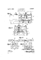
- Figure 3 is a plan view of the valve head
- Figure 4 is a section on the line 44 of Figure 3.
- Figure 5 is a perspective view of one of the retainers for the discharge valves.
- Figure 6 is a like view of one of the valve plates.
- Figures 7 and 8 are enlarged sections taken respectively on the lines 77 and 88 of Figure 3, with the valve plates in position.
- the reference character 10 indicates a portion of a compressor frame or block which includes a pair of cylinders 11. While two cylinders are illustrated, it is apparent that the compressor may include one or any number of cylinders.
- the cylinders are provided with a water jacket 12 for cooling purposes.
- the reference character indicates the cylinder head and this head is likewise provided with a. water jacket 14 which opens through the inner face of the head and communicates with the water jacket of the cylinder as shown at 15.
- the head is removably 1930. Serial No. 447,315.
- Each of the cylinders is provided with inlet and exhaust valves, and inorderto simplify the compressor structure and provide convenient means for assembling and repair, these valves are arranged so that they may be removed and replaced as a unit, whether the compressor is of a singleor multi-cylinder type.
- theinvention provides a valve head 19, which carries the valves.
- This head is provided with'inlet and discharge ports 20 and 21 respectively, which are surrounded by recesses 22.
- valve retainers 25 Located within the recess 22 of the valve head 19 are valve retainers 25.
- One of these retainers for the discharge valves isshown in detail in Figure 5 of thedrawings. .
- One of these retainers fits'within eachof therecesses 22 over or-under eachpairT of ports.
- the retainers are provided with longitudinally disposed lugs 26 which are spaced transversely and between which 'thevalve plates .24 are positioned. Limited movement of the valve plates 24 between the ports 23 and the opposed faces 27 of the valve retainers is thus provided. Thus, when the valve plates are unseated, air may pass through the ports past 'the "longitudinal side edges of the retainers.
- the valve head is provided with openings 32 for the passage of bolts or studs 33, and as these bolts or studs serve to secure the cylinder head 13 in place, they likewise provide for securing in place the valve unit,
- the head 19 shown in the drawings is for a two-cylinder compressor, and carries the inlet and exhaust valves for both cylinders.
- the construction may be applied to a single or multi-cylinder compressor, so that the valves of all of the cylinders may be arranged as a singleunit.
- Acompressor valve structure comprising a flat headplate having ports passing therethrough, saidports being surrounded by recesses in the faces of the plate, valve retainers seated inthe recesses and having solid portions disposed oppositethe ends of the ports and spaced therefrom and fiat'parallelopiped valve members disposed in the spaces vbetween the ends of the ports and the solid "portions ofthe retainers said valve plates beingless in transverse thickness than the transverse Width of the spaces.
- A- compressor valve structure comprisingaflat head plate having ports passing therethrough,said ports being surrounded by recesses lnthe faces of the plate, valve retainers seated in the recesses and having solid "ports and'spaced therefrom and flat parallelopiped valve members disposed in the spaces between the ends of:the ports and (the solid portions of theretainers said valveplatesbering less in transverse thickness than the transverse width of the spaces and the retainers having spaced lugs located attheir sides and which snugly receive the end portions of the valve members.
- a retainer comprising-an elongated body provided :at its ends and at its opposite edges with spaced lugs, said body being provided at apoint midway between its ends With atransversely disposed'boss, the boss being located at :the opposite side of the bodyfrom-the lugs and a parallelopiped valve member adaptedtoifit snuglyat its e nds between the lugs.
Landscapes
- Engineering & Computer Science (AREA)
- Mechanical Engineering (AREA)
- General Engineering & Computer Science (AREA)
- Compressor (AREA)
Description
April 1932' c. WAINWRIGHT 1,854,085
COMPRESSOR VALVE UNI T Filed April 25, 1930 2 Sheets-Sheet 2 wmwrgkf,
INVENTOR ATTORNEY cooled vertical compressors.
Patented Apr. 12, 1932 STATES cHARLEswAINwRIeH'r, or ERIE, P NNSYLVANIA COMPRESSOR UNIT 7 Application filed. April 25,
This invention relates to air compressors and has a special reference to inlet and exhaust valves therefor, the invention being designed especially for application to water An object of the present invention is to provide a Valve unit which is detachably secured in place and which includes inlet and exhaust ports, together with openings to provide for a circulation of water around the compressor cylinder and the cylinder head.
With the above and other objects in view, the invention further includes the following novel features and details of construction, to be hereinafter more fully described, illustrated in the accompanying drawings and pointed out in the appended claims.
In the drawings Figure 1 is a fragmentary view partly in section of the upper portion of a vertical air compressor, illustrating the invention.
Figure 2 is a section taken substantially on the line 22 of Figure 1.
Figure 3 is a plan view of the valve head;
Figure 4 is a section on the line 44 of Figure 3.
Figure 5 is a perspective view of one of the retainers for the discharge valves.
Figure 6 is a like view of one of the valve plates.
Figures 7 and 8 are enlarged sections taken respectively on the lines 77 and 88 of Figure 3, with the valve plates in position.
Referring to the drawings in detail where* in like characters of reference denote corresponding parts, the reference character 10 indicates a portion of a compressor frame or block which includes a pair of cylinders 11. While two cylinders are illustrated, it is apparent that the compressor may include one or any number of cylinders. The cylinders are provided with a water jacket 12 for cooling purposes. a
The reference character indicates the cylinder head and this head is likewise provided with a. water jacket 14 which opens through the inner face of the head and communicates with the water jacket of the cylinder as shown at 15. The head is removably 1930. Serial No. 447,315.
secured to the compressor frame or block by means of bolts or studs 33. i
Each of the cylinders is provided with inlet and exhaust valves, and inorderto simplify the compressor structure and provide convenient means for assembling and repair, these valves are arranged so that they may be removed and replaced as a unit, whether the compressor is of a singleor multi-cylinder type. For this purpose theinvention provides a valve head 19, which carries the valves. This head is provided with'inlet and discharge ports 20 and 21 respectively, which are surrounded by recesses 22. The ports 20 and 21 'are'provided with seats 23 having valve plates 24. One of these plates lSillllS- 'trated in Figure 6 ofthe drawings: and is adapted to bepositioned in contact with the seat 23 when the port is closed.
Located within the recess 22 of the valve head 19 are valve retainers 25. One of these retainers for the discharge valves isshown in detail in Figure 5 of thedrawings. .One of these retainers fits'within eachof therecesses 22 over or-under eachpairT of ports.
The retainers are provided with longitudinally disposed lugs 26 which are spaced transversely and between which 'thevalve plates .24 are positioned. Limited movement of the valve plates 24 between the ports 23 and the opposed faces 27 of the valve retainers is thus provided. Thus, when the valve plates are unseated, air may pass through the ports past 'the "longitudinal side edges of the retainers.
In the valve'retainers for the inlet ports,the
ibosses 28are omitted.
also indicated by arrows in the said figure.
The valve head is provided with openings 32 for the passage of bolts or studs 33, and as these bolts or studs serve to secure the cylinder head 13 in place, they likewise provide for securing in place the valve unit,
the discharge ports 21 through passages 31, 7
The head 19 shown in the drawings is for a two-cylinder compressor, and carries the inlet and exhaust valves for both cylinders. Obviously, the construction may be applied to a single or multi-cylinder compressor, so that the valves of all of the cylinders may be arranged as a singleunit.
The invention is susceptible of various changes in its form, proportions and minor details of construction and the right is herein reserved to make such changes-as properly fall Within the scope of the appended claims.
Having described the invention What is claimed is 1. Acompressor valve structure comprising a flat headplate having ports passing therethrough, saidports being surrounded by recesses in the faces of the plate, valve retainers seated inthe recesses and having solid portions disposed oppositethe ends of the ports and spaced therefrom and fiat'parallelopiped valve members disposed in the spaces vbetween the ends of the ports and the solid "portions ofthe retainers said valve plates beingless in transverse thickness than the transverse Width of the spaces.
2.v A- compressor valve structure comprisingaflat head plate having ports passing therethrough,said ports being surrounded by recesses lnthe faces of the plate, valve retainers seated in the recesses and having solid "ports and'spaced therefrom and flat parallelopiped valve members disposed in the spaces between the ends of:the ports and (the solid portions of theretainers said valveplatesbering less in transverse thickness than the transverse width of the spaces and the retainers having spaced lugs located attheir sides and which snugly receive the end portions of the valve members.
3'.- Ina compressor valve a retainer comprising-an elongated body provided :at its ends and at its opposite edges with spaced lugs, said body being provided at apoint midway between its ends With atransversely disposed'boss, the boss being located at :the opposite side of the bodyfrom-the lugs and a parallelopiped valve member adaptedtoifit snuglyat its e nds between the lugs.
In testimony whereof I afiix myrsignature.
CHARLES WAIN-WRIGHT.
Priority Applications (1)
| Application Number | Priority Date | Filing Date | Title |
|---|---|---|---|
| US447315A US1854085A (en) | 1930-04-25 | 1930-04-25 | Compressor valve unit |
Applications Claiming Priority (1)
| Application Number | Priority Date | Filing Date | Title |
|---|---|---|---|
| US447315A US1854085A (en) | 1930-04-25 | 1930-04-25 | Compressor valve unit |
Publications (1)
| Publication Number | Publication Date |
|---|---|
| US1854085A true US1854085A (en) | 1932-04-12 |
Family
ID=23775871
Family Applications (1)
| Application Number | Title | Priority Date | Filing Date |
|---|---|---|---|
| US447315A Expired - Lifetime US1854085A (en) | 1930-04-25 | 1930-04-25 | Compressor valve unit |
Country Status (1)
| Country | Link |
|---|---|
| US (1) | US1854085A (en) |
-
1930
- 1930-04-25 US US447315A patent/US1854085A/en not_active Expired - Lifetime
Similar Documents
| Publication | Publication Date | Title |
|---|---|---|
| US2576848A (en) | Obturator or valve | |
| US1854085A (en) | Compressor valve unit | |
| US3203408A (en) | Liquid cooling system for internal combustion engines | |
| US2182990A (en) | Internal combustion engine | |
| US2339972A (en) | Cylinder head | |
| US1668865A (en) | Valve mechanism | |
| US1161223A (en) | Valve mechanism for internal-combustion engines. | |
| US1700372A (en) | Valve for compressors | |
| US2028138A (en) | Internal combustion engine valve mechanism | |
| US1634811A (en) | Pump | |
| US2373537A (en) | Valve mechanism for steam engines | |
| US1780524A (en) | Plate valve | |
| US1660942A (en) | Air-supply system for two-stroke-cycle engines | |
| US2563348A (en) | Cylinder structure for internalcombustion engines | |
| US1270124A (en) | Internal-combustion engine. | |
| US1705216A (en) | Fluid-circulation unit for pumps | |
| US1918247A (en) | Compressor mechanism | |
| US541665A (en) | Steam-engine | |
| DE972226C (en) | Cylinder head for air-cooled single-cylinder and two-cylinder boxer or V engines | |
| US2193576A (en) | Double acting diesel engine | |
| FI82299B (en) | Direct-flow valve | |
| US2349784A (en) | Reciprocating pump | |
| US1642735A (en) | Internal-combustion engine | |
| DE567575C (en) | Cooling device for multi-cylinder internal combustion engines | |
| GB422297A (en) | Improvements relating to steam engine cylinder castings |