US1854084A - Boiler - Google Patents
Boiler Download PDFInfo
- Publication number
- US1854084A US1854084A US473430A US47343030A US1854084A US 1854084 A US1854084 A US 1854084A US 473430 A US473430 A US 473430A US 47343030 A US47343030 A US 47343030A US 1854084 A US1854084 A US 1854084A
- Authority
- US
- United States
- Prior art keywords
- plates
- heater
- plate
- water
- magazine
- Prior art date
- Legal status (The legal status is an assumption and is not a legal conclusion. Google has not performed a legal analysis and makes no representation as to the accuracy of the status listed.)
- Expired - Lifetime
Links
- XLYOFNOQVPJJNP-UHFFFAOYSA-N water Substances O XLYOFNOQVPJJNP-UHFFFAOYSA-N 0.000 description 89
- 239000000446 fuel Substances 0.000 description 25
- 239000002184 metal Substances 0.000 description 23
- 229910052751 metal Inorganic materials 0.000 description 23
- 238000010276 construction Methods 0.000 description 14
- 238000002485 combustion reaction Methods 0.000 description 12
- 125000006850 spacer group Chemical group 0.000 description 8
- XEEYBQQBJWHFJM-UHFFFAOYSA-N Iron Chemical compound [Fe] XEEYBQQBJWHFJM-UHFFFAOYSA-N 0.000 description 6
- 238000005304 joining Methods 0.000 description 5
- 239000012530 fluid Substances 0.000 description 4
- 210000003141 lower extremity Anatomy 0.000 description 4
- 238000003466 welding Methods 0.000 description 4
- 229910000746 Structural steel Inorganic materials 0.000 description 3
- 238000005266 casting Methods 0.000 description 3
- 206010022000 influenza Diseases 0.000 description 3
- 229910052742 iron Inorganic materials 0.000 description 3
- 235000000396 iron Nutrition 0.000 description 3
- 230000015572 biosynthetic process Effects 0.000 description 2
- 238000004519 manufacturing process Methods 0.000 description 2
- 230000003014 reinforcing effect Effects 0.000 description 2
- 230000000284 resting effect Effects 0.000 description 2
- 101001044101 Rattus norvegicus Lipopolysaccharide-induced tumor necrosis factor-alpha factor homolog Proteins 0.000 description 1
- 238000004140 cleaning Methods 0.000 description 1
- 239000003245 coal Substances 0.000 description 1
- 239000007789 gas Substances 0.000 description 1
- 230000005484 gravity Effects 0.000 description 1
- 230000001788 irregular Effects 0.000 description 1
- 238000012986 modification Methods 0.000 description 1
- 230000004048 modification Effects 0.000 description 1
- 229920000136 polysorbate Polymers 0.000 description 1
- 239000007787 solid Substances 0.000 description 1
Images


Classifications
-
- F—MECHANICAL ENGINEERING; LIGHTING; HEATING; WEAPONS; BLASTING
- F22—STEAM GENERATION
- F22B—METHODS OF STEAM GENERATION; STEAM BOILERS
- F22B11/00—Steam boilers of combined fire-tube type and water-tube type, i.e. steam boilers of fire-tube type having auxiliary water tubes
Definitions
- This invention relates to heaters and has for its object to provide a construction simple in parts, eflicient in operation, and less costly to manufacture than those heretofore proposed.
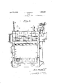
- Fig. 1 is a front elevational view of a complete heater made in accordance with this invention.
- Fig. 2 is a general longitudinal vertical sectional view illustrating the interior construction of the heater
- Fig. 3 is a vertical sectional view taken transversely of the heater
- Figs. 4, 5, 6 and 7 are diagrammatic perspective views illustrating steps in the 21- Fig. 8 is a perspective view of the inner face of the back section of the'heater;
- Fig. 9 is a perspective view illustrating the construction on the inner side of the front section of the heater.
- Fig. 10 is an elevational view of the parts shown in Fig. 9;
- Fig. 11 is a fragmentary horizontal view showing the construction at a'corner of the heater and taken for example as on the line l111 ofFig. 3 and looking in the direction of the arrows;
- Fig. 12 is a general transverse vertical sectional view of a modified form of heater made in accordancewith this invention.
- this heater is somewhat similar to the sectional magazine feed type heatersheretofore known, in general lines of construction, but it differs therefrom in that this heater is made of sheet metal to reduce the manufacturing costs, and is not made 1n sectlons as commonly understood and whereby heaters of differingv the front to the back of the heater.
- the present construction provides for an inclined grate, the highest point of which is immediately below the throat of the fuel magazine so that the fuel from the latter upon reaching the grate will gradually slide or move thereover, as it is being'consumed', to the lowest portion of the grate where substantially nothing but ash remains.
- a continuous sheet metal plate which is of 'a length thatit may be circularly bent around to provide a main body. portion 1 constituting the outer left wall of the heater and a shorter portion 2' constituting one wall of the fuel magazine,
- portion 2 being substantially parallel to l the main body portion but spaced therefrom to provide room fora purality of flue pipes.
- the extreme end edge 40f the portion 3 being disposed notquite one half the distance from thetop 5'ofthe curved'portion of the plate to the other floor engaging end edge 6 at the bottom of the main body portion.
- the vertical dimension of this peculiarly formed sheet from the base edge 6 to the top 5 ofthe curved portion, is approximately 5 feet the spacing of the portion 2 from the main body portion 1 is approximately 14 inches; the horizontal distance from the end 4 of the sheet to the main body portion 1 is approximately 20 inches; and the vertical distance of the edge 4 below the top 5 of the curved portion is approximately 26 plate is rectangularly bent to provide, adjacent.
- the portion 12. extends horizontally to a point near the bond between the sections 2 and 3 of the aforementioned plate, at which point said second plate is bent to provide a downwardly and inclined" section 13 which is parallelly spaced substantially two inches from the section 3 of the other plate, the end portion of the section 13 having a quarter circular bend to bring its extreme edge 14 in position to be welded to the edge 4 of the other plate.
- spacers such as 20 are welded .between the main bodyportions 1 and 10..as well as between the sections 3 and 13. Also a plurality of vertical spacing rods 21 are disposed between the top 5 and the bottom 12? of the domed water chamber 16, and a. plurality of horizontally disposed reinforcing: rods 22 are rigidly secured between thennain: body portion 1 and the section 2 of the outer: plate (see Fig. 3).
- Theright side of this heater comprises two welded continuous plates 23' and 24, spaced fromfeachi other to provide therebetween a second: water leg25 ,.see Fig. 5.
- the outside plate 23 rests vertically upon the floor, is perfectly plane, and; of a: length substantially equal to the vertical-distance between the floor and-thebottomzwall 12of the water chamber.
- The-inside plate 24' parallel to the plate 23,
- each opposite end portion provided with a quarter circular bend with the cxtremeedges 26 and 27 welded or otherwise secured to the plate 23, the edge 27 being secured at or closely acent to the top edge 28 of the plate 23, and the lower edge 26 being approximately 21 inches from the floor.
- Similar reinforcing spacers 20 are provided between the plates 23 and 24, the plate 23 forming. a portion of the wall of the fuel magazine as well as the other side of, the constricted throat thereof.
- the left and right sides of the heater are joined at the top by a bent plate, the bend having the same radius of curvature as that used to produce the curved dome 5 of the water chamber 16, and the plate so dimensioned and formed as to provide, adjacent the bend, a section 30 whose edge 31 is abuttingly welded to the top edge 28 of the plate 23, and another section whose edge 33 is welded to the top surface of the dome of the water chamber 16.
- the section 30 is disposed in the plane of the plate 23 and forms the upper side of the fuel magazine, while the'section 32 forms the horizontal roof of said magazine as well as the major portion of the roof of the heater.
- the front of the heater comprises a continuous plane plate indicated by the numeral 40, see Figs..9 and 10, provided near the top with an aperture 41 adapted to register with the main portion of the fuel magazine and through which said magazine is charged.
- A. second aperture 42 is provided substantially half way down the plate and adapted to register with the combustion chamber, and at the bottom of the plate is a third opening 43 adapted to provide access to the ash pit.
- the edges of the plate 40 are of a contour designed to register with the side edges of the plates 1, 23 and 30' and to be welded thereto, but here it should he stated that the inner plates 10 and 24 are not of the same width as their associated plates 1 and 23 respectively.
- the inner plates are narrower, andare positioned to have their vertical edges stepped back substantially two inches from the adjacent and corresponding edges of their associated outer plates.
- the purpose of this is toprovide a ready means for welding the vertical edges of said inner plates to the inner plates associated with the front and back sections of the heater.
- the front plate has a narrower plate 44 secured thereto and separated therefrom as by the spacers 20, the plate 44 being so spaced that its vertical side edges will register for welding with the vertical edges of the inner side plates 10 and 24.
- the vertical edge 45 of the plate 44 is stepped back about 2 inches from the corresponding edge of the plate 40 and weldingly secured to the vertical edge of the inner side plate 24, and
- the plate 44 is of irregular form or con tour which will be more readily understood from the figures of drawings than from any description that can be written, but it might be particularly'stated that it has a lo oblique section which has the same inclination as that of the grate in order that the front wall of the combustion chamber and the grate will be water jacketed.
- a fourth opening 47 is provided in the plate 40 just above the opening 42 for the purpose of cleaning out the interior flue space in the assembled heater, and around the opening 47 there is welded a narrow sheet, metal strip 48 substantially 2 inches in width, asimilar strip being provided around the opening 42, along the top of the plate 44 and along the bottom edge thereof, said strips being welded in place whereby it will be seen there is provided a closed water jacket space between the plates 40 and 44 when the heater is assembled.
- the inner plate 44 has an opening 49 therethrough adapted to register with the lower portion of the space 17 of the jacketed magazine throat, whereby water may pass between said throat jacket and the water jacket of the front of the heater, it being understood that the edges of the wall sections 12 and 18, forming the top of the combustion chamber, as well as the edge of the wall section 3, forming one side of the fuel magazine throat, will be welded to the exposed surface of the plate 44.
- the rear of the heater comprises a continuous plane plate 50 of the same contour tica-l edge of the inner plate 24 of the right row strips of sheet metal substantially two inches in width, similar to the strip 48 shown in Fig. 9, said strips welded in place between the plates 50 and 52 so as: to form a water jacket on the rear wall of the assembled heater.
- An aperture 55 is provided in the plate 52similar'tothe aperture 49"and also furnishing communication between the rear water jacket and .the jacketed magazine throat.
- the edges of the outer rear plate50 are welded to the rear edges of the plates l, 24 and 30, the edgesof the inner wall sections 3, 12' and 13 are welded to the exposed surface of the rear inner plate. 52, and the opposite edgesof the wall section 2 are welded to the inner surfaces of the front and rear outer plates 40 and '50.
- a plurality of substantially parallel and horizontal flue pipes '60 extend through the water chamber 16 with their opposite ends welded into suitable openings 61 and 62 in the front and rear plates 40 and 50 respectively, and a plurality of water conducting pipes 63 extend between the front and rear water jackets, having their ends welded in suitable openings 64 and 65 in the innerwater jacket plates-44 and 52 respectively, theepipes 63 being slightly inclined upwardly at the rear.
- a baffle plate 66 is disposed over the water pipes 63- between the side plate 10 and the wall section 13 of the magazine throat jacket,
- baffle joined to the plate 44 and extending substantially two-thirds the distance he tween thefront and rear water jackets, whereby the gases of combustion will pass from the burning'fuel upwardly and rearwardly, thence aroundthe free end of the baflie plate 66, thence forwardly under the water chamber 16, thence rearwardly through the flue pipes 6O, and out of the heater through the stack connection 67 provided with a damper 68 and secnredto the rear ofthe heater.
- the grate may be of any suitable construction but preferably comprises a rectangular frame made of angle irons, the front and back "irons 70. and 71 respectively having their flanges uppermost toserve as ledges'for the 7 fuel against the front andfrear water ackets (see Fig. 2), while the side irons have their flanges .reversed (see Fig- 3)-.to permit the frame to fit theheater. That is to say, this heater-is of the fuel magazine type with a grate inclined downwardly from the magazine side, and hence the frame, for the grate is disposed obliquely across the heater.
- the front and back "irons 70. and 71 respectively having their flanges uppermost toserve as ledges'for the 7 fuel against the front andfrear water ackets (see Fig. 2), while the side irons have their flanges .reversed (see Fig- 3)-.to permit the frame to fit theheater.
- angle iron 72 forming theleft and lower side of the grate frame has its flange at the bottom to rest on the supporting brackets. 35 while the upper web edge of said iron will just clear the inner water leg plate 10.
- angle iron 73 forming the right and u per side of the grate frame has its lower we edge resting on the supporting brackets 36, and its flange at the top just clearing the inner water leg plate 241, as a result of which said flange offers a solid smooth surface upon which the fuel from the maga zine falls and slides from in the natural direction of the grate.
- Each grate section referably comprises a hollow tube or pipe 6 supportedly fitting a lug and its opposed pocket, said tube having mounted thereon two grates 7 7 and 78 adapted to be rocked by the shaker bars 79 and 80 respectively, which bars extend through twin slots 81 in the front outer plate 40 and are pivotally connected to. well known twin cranks indicated at 82 in Fig. 1 operable by the usual hand shaker levers not shown.
- baflies 86 and 87 are also connected to the domed water chamber 16.
- the return service pipe 90 is connected to the rear plate 50 at the water jacket thereof.
- Drain or clean out plugs 91 are tapped into the front and rear plates 40 and 50 at convenient and appropriate locations, doors are provided to close the openings 41, 42, 13, 47 at the front, and a draft damper casting 92 is provided at the rear to close the opening 51.
- the modification illustrated in Fig. '12 shows a double heater of substantially the same type of construction in that sheet metal plates are utilized to form the walls of the heater, the only difference being in the formation of the water chamber and jacketed magazine throat. That is to say the right side *of this modified heater comprises an assemblage of plates 100 and 101 of the same shape and dimensions as the plates 23 and 24: heretofore described. To the top edge of the plate 100 is welded a curved plate 102 which is a substantial duplicate of the aforementioned plate 30.
- the left .side of the heater comprises an assemblage of plates 1'03, 104, and 105'w'hich are exact duplicates of the plates 100, 101, and 102 except that they are reversely formed, as will be understood. Both the left and right sides have attached to their outer plates a plurality of brackets 106 which are the duplicates of the brackets 36 illustrated in Fig. 3.
- the water chambers of this double heater are disposed centrally thereof and have a construction slightly different from that of the water chamber heretofore described.
- a plate which is provided with a pluralityof bends and which extends from the weld joint 107 to the weld joint 108 and which includes a central vertical section 109, a horizontal section 110 which ultimately forms the floor of the water chamber 111 as well as a portion of the roof of the combustion chamber 112, and a downwardly and outwardly inclined section 118 which forms one side wall of the water jacket 114 associated with the throat of the fuel magazine 115.
- a second plate extends from the weld joint 10'?
- the plate 102 is welded to the wall of the water chamber as at the point 118.
- plates are provided in the left side of the double heater to provide the companion water rhamber 120.
- this heater there is a plate extending from the weld joint 121 to a second weld joint 122 and which includes a vertical wall section 123 adapted to contact the wall section 109 of the water chamber 111, a section 121 which lies in the same horizontal plane with the section 110, and an oblique section 125 symmetrical with the section 113.
- a second plate extends between the weld joints 121 and 122 and has the vertical section 126 forming the other side of the water chamber 120, and the oblique section 127 parallel to and separated as by the spacers 20 from the oblique section 125 toform therebetween the water ackct 128 associated with the throat of the fuel magazine 129 on the left side of the heater.
- the front and rear sections of this heater are formed similarly to the front and rear sections of the single heater hereinbefore described, ex: cept as to size.
- a plate 136 At the floor line of the double heater and centrally thereof, is a plate 136 disposed vertically and extending from the front section to the rear section, and to the top of this plate is suitably secured a casting 137 having formed on its opposite sides lugs such as indicated at 188 adapted to receive one end of a grate member generally indicated by the numeral 139, the opposite end of which is dropped into a pocket such as 140 formed on the angle iron 14:1 resting upon the brackets 106.
- the casting 137 is disposed a substantial distance below the brackets 106 whereby the grate sections 139 are given inclinations downwardly'fromthe sides of the the heater, as a result of which fuel from the magazines 115 and 129 will drop upon the elevated ends of the grates, and slide thereover in a direction toward the center of the heater while being consumed.
- aheaterof the magazine feed type which comprises four outer walls 1, 24, 450 and 50 each formed by a plate of sheet metal, a top formed by an extension of oneof the outer walls and another plate joining said extension with the opposite side wall 24, said extension 5 continued interiorly of said heater to form one side 2 of a fuelymagazine, the edges of said walls and said top welded to provide a closed casing, an inner plate (10, 23, 4A, 52)*secured in spaced relation to each plate of the outer wall the vertical edges of the inner plates welded toprovide a continuous combustion chamber wall, one of the inner plates 10 extended and joined to the interior end 1 0f the extended outer plate to provide therebetween a water chamber 16,'and the lower edges of said inner platesjoined to the outer plates to provide water legs and water jackets or headers communicating with the water chamber, the joined outer walls constituting the outer shell and the joined inner walls providing an inner shell, the vertical edges of the inner plates being stepped backfrorn the corresponding
- a heater of the magazine feed type comprising outer plates of sheet metal welded at their edges to provide the outer casing of the heater, one of said plates extended downwardly interiorly of the casing to form one wall of the magazine; inner plates of sheet metal secured to saidouter plates in spaced relation the edges of said inner plates welded together to provide water jackets on the front and rear and water'legs on the opposite sides of the heater, one of said inner plates ex-' tended inwardly and downwardly interiorly of the extended outer plate to form therewith a water chamber at the top of the heater and an oblique downward extension'thereof conber and the latter communicating with saidwater jackets; an inlet and an outlet for conducting fluid to and from the heater; an inclined grate disposed between the lower extremities'of said water legs; and draft openings in't'he outer plates.
- a heater of the magazine feed type comprising outer plates of sheet metal welded at their edges to provide the outer casing of the heater, one of said plates extended downwardly interiorly of the casing to form one wall of the magazine; inner plates of sheet metal secured to said outer plates in spaced relation the edges of said inner plates welded together to provide water jackets on the 2 stricted threat at the bottom of the magazine,
- said chamber extension inopen communication withsaid water ackets; tubes extending from the front to the rear their ends supported by opposite outer and opposite inner plates, said tubes constituting respectively fines and water conducting passages the for mer passing through said water chamber and the latter communicating with said water jackets; an. inlet and an outlet for co-nducting fluid to and from the heater; an inclined grate disposed between the lower extremities of said water legs; and draft openings in the outer plates.
- a heater of the magazine feed type comprising outer plates of sheet metal welded at their edges to provide the outer casing of the .heater, one of said plates extended downwardly interiorly of the casing to form one wall of the magazine; combustion chamber.
- one of said inner plates extended inwardly and downwardlyinteriorly of the extended outer plate to form therewith a water chamber at the top of the heater and an oblique opposite outer and opposite inner plates, said tubes constituting lines and water conducting passages the former passing through said water chamber and the latter passing through the upper portion of the combustion chamber and communicating with said water jackets;
- a heater of the magazine feed type comprising outer plates of sheet metal welded at theiredges to provide the outer casing of the heater, one of said plates extended downwardly interiorly of the casing to form one wall of the magazine; inner plates of sheet metal secured to said outer plates in spaced relation the vertical edges of said inner plates stepped back from the corresponding edges of the outer plates and welded together to provide water jackets on the front and rear and water legs on the opposite sides of the heater, one of said inner plates extended inwardly and downwardly interiorly of the extended outer plate to form therewith a water chamber at the top of the heater and an oblique downward extension thereof constituting a water jacketed constricted throat at the bottom of the magazine; tubesextending from the front to the rear their ends supported by opposite outer and opposite inner plates, said tubes constituting respectively fiues and water conducting passages the former passing through said water chamber and the latter communicating with said water jackets; an inlet and an outlet for conducting fluid to and from the heater; an inclined grate disposed between the lower extremities of said water legs; and draft
- a heater of the magazine feed type consisting of an outer shell and an inner shell, each shell formed by plates of sheet metal welded along their edges one of the plates of the outer shell having a portion bent parallel to the major portion, the bent portion extending interiorly and forming onewall of the magazine, the plates of the inner shell secured in spaced relation to the plates of the outershell by a plurality of interposed spacers, the shells foril'iing therebetween water compartments, tubes constituting flues disposed between the major and bent portions of said outer plate, and an inlet and an outlet communicating with said compartments through the outer shell.
- a heater of the magazine feed type consistlng of an outer shell and an inner shell, each shell formed by plates of sheet metal welded along their edges one of the plates of the outer shell extending interiorly and forming with other plates of said outer shell the fuel magazine, the plates of the inner shell secured in spaced relation to the plates of the outer shell by a plurality of interposed spacers, the shells forming therebetween water compartments, tubes constituting fiues disposed between said one of the outer plates and its extension, and an inlet and an outlet communicating with said compartments through the outer shell.
- a heater comprising four outer walls each formed by a plate of sheet metal; a top formed by an extension of one of the outer walls and another plate joining said extension with the opposite side wall said extension continued interiorly of said heater to form one side of a fuel magazine; the edges of said walls and said top welded to provide a closed casing; an inner plate secured in spaced relation to each plate of the outer wall, the vertical edges of the inner plates welded to provide a continuous combustion chamber wall; one of the inner plates extended and joined to the interior end of the extended outer plate to provide therebetween a water chamber; tubes disposed above and below said last mentioned inner plate forming re spectively flues and water conducting passages; and the lower edges of said inner plates joined to the outer plates to provide water legs and water jackets communicating with said water chamber.
- a heater comprising an inclined grate disposed between four outer walls each wall formed by a plate of sheet metal, a top formed by an extension of one of the outer walls and another plate joining said extension with the opposite side wall said extension continued interiorly of said heater to form one side of a.
- a heater comprising four outer walls each formed by a plate of sheet metal; a top formed by an extension of one of the outer walls and another plate joining said extension with the opposite side wall said extension continued interiorly of said heater to form one side of a fuel magazine; the edges of said walls and said top welded to provide a closed casing; an inner plate secured in spaced relation to each plate of the outer with said water chamber the water legs terminating at their lower ends in different horizontal planes and meeting the top of the grate.
- a sheet metal boiler of the magazine feed type including a water chamber provided with an outlet, a fuel magazine to one side of the water chamber, an inclined hollow extension communicating with and depending from the chamber to form at one side a combustion chamber and at the other side a constricted fuel outlet from the magazine, front and rear headers one of the headers having a water inlet, a water passage from the header into the end of the extension, and a water leg connecting the headers, sheet metal end plates forming the end walls of the Water chamber, and the headers, side plates forming the outer side walls of the water leg and headers united to the end plates, plates forming the inner walls of the headers and water leg united to one another and to the end and side plates, sheet metal side walls for the water chamber and its extension formed of plates welded together a division wall between said chamber and the fuel magazine; and tubes terminating in the end plates, some of said tubes constituting flues passing through said water chamber, and the other of said tubes constituting water-conducting passages joining said water jackets.
- a heater of the magazine feed type consisting of an outer shell and an inner shell, each shell formed by plates of sheet metal welded along their edges one of the plates of the outer shell having a portion bent parallel to the major portion, the bent portion extending interiorly and forming the inner wall of the magazine, the plates ofthe inner shell secured in spaced relation to the plates of the outer shell'by a plurality of interposed spacers, the shells forming therebetween water compartments, tubes constituting fiues disposed between said inner magazine wall and one of the plates of the outer shell, and an inlet and an outlet communicating with said compartments through the outer shell.
Landscapes
- Engineering & Computer Science (AREA)
- Physics & Mathematics (AREA)
- Thermal Sciences (AREA)
- Mechanical Engineering (AREA)
- General Engineering & Computer Science (AREA)
Description
April J. A. WADDELp v 1,854,084
'BOILER Filed Aug. 6, 1930 4 Sheets-Sh eet 1 Inwcutor JA. 74 a'ddeZZ I] I I mung April 12, 1932. J. A. WADDELL BOILER Filed Aug, 6. 1950 4 Sheets-Sheet 2 lnnentor JA. We Z2 Gttorneg April 12, 1932. wADDELL 1,854,084
BOILER Filed Aug. 6, 1930 4 Sheets-Sheet 3 %.g9, I 3nventor (IA. VVZLdeZeZZ April 12, 1932.
J. A. WADDELL BOILER Filed Aug. 6, 1950 4 Sheets-Sheet 4 ISnnentor JA. WddZZ/ semblage of the heater;
Patented Apr. 12, 1932 ITED STATES PATENT oFFIcE JOSEPH A. WADDELL, OF WILLIAMSPORT, PENNSYLVANIA, ASSIGNOR TO SPENCER HEATER COMPANY, OF WILLIAMSPORT, PENNSYLVANIA, A CORPORATION OF PENN- SYLVANIA BOILER Application filed August 6, 1930. Serial 110,473,430.
This invention relates to heaters and has for its object to provide a construction simple in parts, eflicient in operation, and less costly to manufacture than those heretofore proposed.
With these and other objects in view the invention resides in the novel details of construction and combinations of parts as will be disclosed more fully hereinafter and par- .1 ticularly pointed out in the claims.
Referring to the accompanying drawings forming a part of this specification in which like numerals designate like parts mall the views,
Fig. 1 is a front elevational view of a complete heater made in accordance with this invention; V
Fig. 2 is a general longitudinal vertical sectional view illustrating the interior construction of the heater;
Fig. 3 is a vertical sectional view taken transversely of the heater;
Figs. 4, 5, 6 and 7 are diagrammatic perspective views illustrating steps in the 21- Fig. 8 is a perspective view of the inner face of the back section of the'heater;
Fig. 9is a perspective view illustrating the construction on the inner side of the front section of the heater;
Fig. 10 is an elevational view of the parts shown in Fig. 9;
Fig. 11 is a fragmentary horizontal view showing the construction at a'corner of the heater and taken for example as on the line l111 ofFig. 3 and looking in the direction of the arrows;
Fig. 12 is a general transverse vertical sectional view of a modified form of heater made in accordancewith this invention; and
" wherein a compartment may be filled with coal or other suitable fuel which automatically feeds downwardly, under the urge of gravity, to the grate. Also this heater is somewhat similar to the sectional magazine feed type heatersheretofore known, in general lines of construction, but it differs therefrom in that this heater is made of sheet metal to reduce the manufacturing costs, and is not made 1n sectlons as commonly understood and whereby heaters of differingv the front to the back of the heater. Also the present construction provides for an inclined grate, the highest point of which is immediately below the throat of the fuel magazine so that the fuel from the latter upon reaching the grate will gradually slide or move thereover, as it is being'consumed', to the lowest portion of the grate where substantially nothing but ash remains. r r
Vith particular referenceto Figs. 4: to 10, it is believed that the general construction of this heater may be readily-understood. There is provided a continuous sheet metal plate which is of 'a length thatit may be circularly bent around to provide a main body. portion 1 constituting the outer left wall of the heater and a shorter portion 2' constituting one wall of the fuel magazine,
the portion 2 being substantially parallel to l the main body portion but spaced therefrom to provide room fora purality of flue pipes.
1, to form one side of the constricted throat of said magazine, the extreme end edge 40f the portion 3 being disposed notquite one half the distance from thetop 5'ofthe curved'portion of the plate to the other floor engaging end edge 6 at the bottom of the main body portion. By way ofexample onlyand in order that some ideaof relative size of this heater may be had the vertical dimension of this peculiarly formed sheet, from the base edge 6 to the top 5 ofthe curved portion, is approximately 5 feet the spacing of the portion 2 from the main body portion 1 is approximately 14 inches; the horizontal distance from the end 4 of the sheet to the main body portion 1 is approximately 20 inches; and the vertical distance of the edge 4 below the top 5 of the curved portion is approximately 26 plate is rectangularly bent to provide, adjacent. the main body portion 10, a section 12. which ultimately forms the floor of the main water chamber of this heater, as well as the roof of the combustion chamber. The portion 12. extends horizontally to a point near the bond between the sections 2 and 3 of the aforementioned plate, at which point said second plate is bent to provide a downwardly and inclined" section 13 which is parallelly spaced substantially two inches from the section 3 of the other plate, the end portion of the section 13 having a quarter circular bend to bring its extreme edge 14 in position to be welded to the edge 4 of the other plate.
From the foregoing it will thus be: seen that the left side of this heater isformed by two' metallic plates each bent and both oined by welding to produce a space 15 between the major portions thereof which space ultimately becomes a waterleg in the completely assembled. heater.- Saidplates are further assembleditoprovide the domed space 16 which ultimately becomes the main water chamber of said heater and said sheets are still further: disposed. to provide the space 17 which ultimately becomes. the water jacketed: throat ofthe-fuel magazine. For the purpose ofexample-only, the lower joint between the two plates1and10 is made substantially 11 inches above thefloor,
During assemblage and in order to'rigidly maintain spacing, spacers such as 20 are welded .between the main bodyportions 1 and 10..as well as between the sections 3 and 13. Alsoa plurality of vertical spacing rods 21 are disposed between the top 5 and the bottom 12? of the domed water chamber 16, and a. plurality of horizontally disposed reinforcing: rods 22 are rigidly secured between thennain: body portion 1 and the section 2 of the outer: plate (see Fig. 3).
Theright side of this heater comprises two welded continuous plates 23' and 24, spaced fromfeachi other to provide therebetween a second: water leg25 ,.see Fig. 5. The outside plate 23rests vertically upon the floor, is perfectly plane, and; of a: length substantially equal to the vertical-distance between the floor and-thebottomzwall 12of the water chamber. The-inside plate 24' parallel to the plate 23,
has each opposite end portion provided with a quarter circular bend with the cxtremeedges 26 and 27 welded or otherwise secured to the plate 23, the edge 27 being secured at or closely acent to the top edge 28 of the plate 23, and the lower edge 26 being approximately 21 inches from the floor. Similar reinforcing spacers 20 are provided between the plates 23 and 24, the plate 23 forming. a portion of the wall of the fuel magazine as well as the other side of, the constricted throat thereof.
The left and right sides of the heater are joined at the top by a bent plate, the bend having the same radius of curvature as that used to produce the curved dome 5 of the water chamber 16, and the plate so dimensioned and formed as to provide, adjacent the bend, a section 30 whose edge 31 is abuttingly welded to the top edge 28 of the plate 23, and another section whose edge 33 is welded to the top surface of the dome of the water chamber 16. The section 30 is disposed in the plane of the plate 23 and forms the upper side of the fuel magazine, while the'section 32 forms the horizontal roof of said magazine as well as the major portion of the roof of the heater. In the completely assembled heater the left and right sides will be parallel to each other with a spacing of substantially six inches between the edge 4 of the throat of the fuel magazine and the inner plate 24 of the water leg 25. Up to this point the foregoing description covers the assemblage of the heater to produce the construction shown in Fig- 6, there being provided on the inner face of the plate 1 a plurality of brackets 35, and on the-inner'face of the opposite plate 23a plurality of brackets 36 which are disposed below the water legs for the purpose of supporting the grate assembly.
The front of the heater comprises a continuous plane plate indicated by the numeral 40, see Figs..9 and 10, provided near the top with an aperture 41 adapted to register with the main portion of the fuel magazine and through which said magazine is charged. A. second aperture 42 is provided substantially half way down the plate and adapted to register with the combustion chamber, and at the bottom of the plate is a third opening 43 adapted to provide access to the ash pit. The edges of the plate 40 are of a contour designed to register with the side edges of the plates 1, 23 and 30' and to be welded thereto, but here it should he stated that the inner plates 10 and 24 are not of the same width as their associated plates 1 and 23 respectively. In other words, the inner plates are narrower, andare positioned to have their vertical edges stepped back substantially two inches from the adjacent and corresponding edges of their associated outer plates. The purpose of this is toprovide a ready means for welding the vertical edges of said inner plates to the inner plates associated with the front and back sections of the heater.
That is to say, the front plate has a narrower plate 44 secured thereto and separated therefrom as by the spacers 20, the plate 44 being so spaced that its vertical side edges will register for welding with the vertical edges of the inner side plates 10 and 24. In order that this construction may be understood more clearly, it is stated that the vertical edge 45 of the plate 44 is stepped back about 2 inches from the corresponding edge of the plate 40 and weldingly secured to the vertical edge of the inner side plate 24, and
i the other opposite vertical edge 46 of said plate 44 is likewise stepped back and welded to the vertical edge of the inner side plate 10, it being understood, of course, that the side edges of the plate 40 will also be welded to the edges of the outer side plates 1 and 24.
The plate 44 is of irregular form or con tour which will be more readily understood from the figures of drawings than from any description that can be written, but it might be particularly'stated that it has a lo oblique section which has the same inclination as that of the grate in order that the front wall of the combustion chamber and the grate will be water jacketed. A fourth opening 47 is provided in the plate 40 just above the opening 42 for the purpose of cleaning out the interior flue space in the assembled heater, and around the opening 47 there is welded a narrow sheet, metal strip 48 substantially 2 inches in width, asimilar strip being provided around the opening 42, along the top of the plate 44 and along the bottom edge thereof, said strips being welded in place whereby it will be seen there is provided a closed water jacket space between the plates 40 and 44 when the heater is assembled. The inner plate 44 has an opening 49 therethrough adapted to register with the lower portion of the space 17 of the jacketed magazine throat, whereby water may pass between said throat jacket and the water jacket of the front of the heater, it being understood that the edges of the wall sections 12 and 18, forming the top of the combustion chamber, as well as the edge of the wall section 3, forming one side of the fuel magazine throat, will be welded to the exposed surface of the plate 44.
The rear of the heater comprises a continuous plane plate 50 of the same contour tica-l edge of the inner plate 24 of the right row strips of sheet metal substantially two inches in width, similar to the strip 48 shown in Fig. 9, said strips welded in place between the plates 50 and 52 so as: to form a water jacket on the rear wall of the assembled heater. An aperture 55 is provided in the plate 52similar'tothe aperture 49"and also furnishing communication between the rear water jacket and .the jacketed magazine throat. The edges of the outer rear plate50 are welded to the rear edges of the plates l, 24 and 30, the edgesof the inner wall sections 3, 12' and 13 are welded to the exposed surface of the rear inner plate. 52, and the opposite edgesof the wall section 2 are welded to the inner surfaces of the front and rear outer plates 40 and '50.
A plurality of substantially parallel and horizontal flue pipes '60 extend through the water chamber 16 with their opposite ends welded into suitable openings 61 and 62 in the front and rear plates 40 and 50 respectively, and a plurality of water conducting pipes 63 extend between the front and rear water jackets, having their ends welded in suitable openings 64 and 65 in the innerwater jacket plates-44 and 52 respectively, theepipes 63 being slightly inclined upwardly at the rear. A baffle plate 66 is disposed over the water pipes 63- between the side plate 10 and the wall section 13 of the magazine throat jacket,
said baffle joined to the plate 44 and extending substantially two-thirds the distance he tween thefront and rear water jackets, whereby the gases of combustion will pass from the burning'fuel upwardly and rearwardly, thence aroundthe free end of the baflie plate 66, thence forwardly under the water chamber 16, thence rearwardly through the flue pipes 6O, and out of the heater through the stack connection 67 provided with a damper 68 and secnredto the rear ofthe heater. 1 (See Fig. 2.) a
The grate may be of any suitable construction but preferably comprises a rectangular frame made of angle irons, the front and back "irons 70. and 71 respectively having their flanges uppermost toserve as ledges'for the 7 fuel against the front andfrear water ackets (see Fig. 2), while the side irons have their flanges .reversed (see Fig- 3)-.to permit the frame to fit theheater. That is to say, this heater-is of the fuel magazine type with a grate inclined downwardly from the magazine side, and hence the frame, for the grate is disposed obliquely across the heater. The
The inner face of the frame iron 72 has secured thereto a plurality of lugs 74:, and the inner face of. the opposite frame iron 7 has secured thereto a plurality of plates each pro vided with an upwardly opening pocket 75, the lugs and pockets being opposed to each other and spaced to receive opposite ends of grate sections. Each grate section referably comprises a hollow tube or pipe 6 supportedly fitting a lug and its opposed pocket, said tube having mounted thereon two grates 7 7 and 78 adapted to be rocked by the shaker bars 79 and 80 respectively, which bars extend through twin slots 81 in the front outer plate 40 and are pivotally connected to. well known twin cranks indicated at 82 in Fig. 1 operable by the usual hand shaker levers not shown.
At the top of the water chamber in the plate 1 there is provided a pair of openings such as 83 connected to the steam service pipes 84: and 85, and across the upper region of the water chamber 16 just below each of these openings are baflies 86 and 87 to prevent entry of water into the steam service pipes, said baflies welded in place. A steam gauge 88, as well as a pressure draft regulator generally indicated by the numeral 89 are also connected to the domed water chamber 16. The return service pipe 90 is connected to the rear plate 50 at the water jacket thereof. Drain or clean out plugs 91 are tapped into the front and rear plates 40 and 50 at convenient and appropriate locations, doors are provided to close the openings 41, 42, 13, 47 at the front, and a draft damper casting 92 is provided at the rear to close the opening 51.
The modification illustrated in Fig. '12 shows a double heater of substantially the same type of construction in that sheet metal plates are utilized to form the walls of the heater, the only difference being in the formation of the water chamber and jacketed magazine throat. That is to say the right side *of this modified heater comprises an assemblage of plates 100 and 101 of the same shape and dimensions as the plates 23 and 24: heretofore described. To the top edge of the plate 100 is welded a curved plate 102 which is a substantial duplicate of the aforementioned plate 30. The left .side of the heater comprises an assemblage of plates 1'03, 104, and 105'w'hich are exact duplicates of the plates 100, 101, and 102 except that they are reversely formed, as will be understood. Both the left and right sides have attached to their outer plates a plurality of brackets 106 which are the duplicates of the brackets 36 illustrated in Fig. 3.
The water chambers of this double heater are disposed centrally thereof and have a construction slightly different from that of the water chamber heretofore described. In other words, there is provided on the right hand half of the double heater a plate which is provided with a pluralityof bends and which extends from the weld joint 107 to the weld joint 108 and which includes a central vertical section 109, a horizontal section 110 which ultimately forms the floor of the water chamber 111 as well as a portion of the roof of the combustion chamber 112, and a downwardly and outwardly inclined section 118 which forms one side wall of the water jacket 114 associated with the throat of the fuel magazine 115. A second plate extends from the weld joint 10'? to the weld joint 108 and which is provided with a plurality of bends to form the other vertical side wall section 116 of the water chamber 111, and the section 117 which is parallel to the section 113 and forms therewith the other wall of the water jacket 114;, spacers such as 20 being provided to reinforce and maintain the rigidity of said water jacket. The plate 102 is welded to the wall of the water chamber as at the point 118.
In a similar manner but in reverse formation plates are provided in the left side of the double heater to provide the companion water rhamber 120. In other words, on the left side of this heater there is a plate extending from the weld joint 121 to a second weld joint 122 and which includes a vertical wall section 123 adapted to contact the wall section 109 of the water chamber 111, a section 121 which lies in the same horizontal plane with the section 110, and an oblique section 125 symmetrical with the section 113. A second plate extends between the weld joints 121 and 122 and has the vertical section 126 forming the other side of the water chamber 120, and the oblique section 127 parallel to and separated as by the spacers 20 from the oblique section 125 toform therebetween the water ackct 128 associated with the throat of the fuel magazine 129 on the left side of the heater.
Extending from the front section to the rear section through the water chambers 111 and 120 are flue pipes similar to the pipes 60, and below the water chambers and between the water jacketed throats of the fuel 1nagazines is provided a plurality of water conducting pipes similar to the pipes 63, with a baffle 185 extending thereover. The front and rear sections of this heater are formed similarly to the front and rear sections of the single heater hereinbefore described, ex: cept as to size. At the floor line of the double heater and centrally thereof, is a plate 136 disposed vertically and extending from the front section to the rear section, and to the top of this plate is suitably secured a casting 137 having formed on its opposite sides lugs such as indicated at 188 adapted to receive one end of a grate member generally indicated by the numeral 139, the opposite end of which is dropped into a pocket such as 140 formed on the angle iron 14:1 resting upon the brackets 106. The casting 137 is disposed a substantial distance below the brackets 106 whereby the grate sections 139 are given inclinations downwardly'fromthe sides of the the heater, as a result of which fuel from the magazines 115 and 129 will drop upon the elevated ends of the grates, and slide thereover in a direction toward the center of the heater while being consumed.
- Thus itwill be seen from the foregoing, that there is provided aheaterof the magazine feed typewhich comprises four outer walls 1, 24, 450 and 50 each formed by a plate of sheet metal, a top formed by an extension of oneof the outer walls and another plate joining said extension with the opposite side wall 24, said extension 5 continued interiorly of said heater to form one side 2 of a fuelymagazine, the edges of said walls and said top welded to provide a closed casing, an inner plate (10, 23, 4A, 52)*secured in spaced relation to each plate of the outer wall the vertical edges of the inner plates welded toprovide a continuous combustion chamber wall, one of the inner plates 10 extended and joined to the interior end 1 0f the extended outer plate to provide therebetween a water chamber 16,'and the lower edges of said inner platesjoined to the outer plates to provide water legs and water jackets or headers communicating with the water chamber, the joined outer walls constituting the outer shell and the joined inner walls providing an inner shell, the vertical edges of the inner plates being stepped backfrorn the corresponding edges of the outer plates to facilitate in the assemblage and welding of the plates to form the heater.
It is obviousthat thoseskilled in the art may vary the details of construction and arran ement of partswithout departing from the spirit of theinvention, and therefore it is not desired to be limitedto the foregoing except as may be desired by the claims.
What is claimed is 1. A heater of the magazine feed type comprising outer plates of sheet metal welded at their edges to provide the outer casing of the heater, one of said plates extended downwardly interiorly of the casing to form one wall of the magazine; inner plates of sheet metal secured to saidouter plates in spaced relation the edges of said inner plates welded together to provide water jackets on the front and rear and water'legs on the opposite sides of the heater, one of said inner plates ex-' tended inwardly and downwardly interiorly of the extended outer plate to form therewith a water chamber at the top of the heater and an oblique downward extension'thereof conber and the latter communicating with saidwater jackets; an inlet and an outlet for conducting fluid to and from the heater; an inclined grate disposed between the lower extremities'of said water legs; and draft openings in't'he outer plates. I
2. A heater of the magazine feed type comprising outer plates of sheet metal welded at their edges to provide the outer casing of the heater, one of said plates extended downwardly interiorly of the casing to form one wall of the magazine; inner plates of sheet metal secured to said outer plates in spaced relation the edges of said inner plates welded together to provide water jackets on the 2 stricted threat at the bottom of the magazine,
said chamber extension inopen communication withsaid water ackets; tubes extending from the front to the rear their ends supported by opposite outer and opposite inner plates, said tubes constituting respectively fines and water conducting passages the for mer passing through said water chamber and the latter communicating with said water jackets; an. inlet and an outlet for co-nducting fluid to and from the heater; an inclined grate disposed between the lower extremities of said water legs; and draft openings in the outer plates. I
3. A heater of the magazine feed type comprising outer plates of sheet metal welded at their edges to provide the outer casing of the .heater, one of said plates extended downwardly interiorly of the casing to form one wall of the magazine; combustion chamber.
forming inner plates of sheet metal secured to said outer plates in spaced'relation the edges of said inner plates-welded together to provide water jackets on the front and rear and water legs on the opposite sides of the heater,
one of said inner plates extended inwardly and downwardlyinteriorly of the extended outer plate to form therewith a water chamber at the top of the heater and an oblique opposite outer and opposite inner plates, said tubes constituting lines and water conducting passages the former passing through said water chamber and the latter passing through the upper portion of the combustion chamber and communicating with said water jackets;
an inlet and outlet for conducting fluid to and from the heater; an inclined grate disposed between the lower extremities of said water legs; and draft openings in the outer plates.
4. A heater of the magazine feed type comprising outer plates of sheet metal welded at theiredges to provide the outer casing of the heater, one of said plates extended downwardly interiorly of the casing to form one wall of the magazine; inner plates of sheet metal secured to said outer plates in spaced relation the vertical edges of said inner plates stepped back from the corresponding edges of the outer plates and welded together to provide water jackets on the front and rear and water legs on the opposite sides of the heater, one of said inner plates extended inwardly and downwardly interiorly of the extended outer plate to form therewith a water chamber at the top of the heater and an oblique downward extension thereof constituting a water jacketed constricted throat at the bottom of the magazine; tubesextending from the front to the rear their ends supported by opposite outer and opposite inner plates, said tubes constituting respectively fiues and water conducting passages the former passing through said water chamber and the latter communicating with said water jackets; an inlet and an outlet for conducting fluid to and from the heater; an inclined grate disposed between the lower extremities of said water legs; and draft openings in the outer plates.
5. A heater of the magazine feed type consisting of an outer shell and an inner shell, each shell formed by plates of sheet metal welded along their edges one of the plates of the outer shell having a portion bent parallel to the major portion, the bent portion extending interiorly and forming onewall of the magazine, the plates of the inner shell secured in spaced relation to the plates of the outershell by a plurality of interposed spacers, the shells foril'iing therebetween water compartments, tubes constituting flues disposed between the major and bent portions of said outer plate, and an inlet and an outlet communicating with said compartments through the outer shell.
6, A heater of the magazine feed type consistlng of an outer shell and an inner shell, each shell formed by plates of sheet metal welded along their edges one of the plates of the outer shell extending interiorly and forming with other plates of said outer shell the fuel magazine, the plates of the inner shell secured in spaced relation to the plates of the outer shell by a plurality of interposed spacers, the shells forming therebetween water compartments, tubes constituting fiues disposed between said one of the outer plates and its extension, and an inlet and an outlet communicating with said compartments through the outer shell.
7. A heater comprising four outer walls each formed by a plate of sheet metal; a top formed by an extension of one of the outer walls and another plate joining said extension with the opposite side wall said extension continued interiorly of said heater to form one side of a fuel magazine; the edges of said walls and said top welded to provide a closed casing; an inner plate secured in spaced relation to each plate of the outer wall, the vertical edges of the inner plates welded to provide a continuous combustion chamber wall; one of the inner plates extended and joined to the interior end of the extended outer plate to provide therebetween a water chamber; tubes disposed above and below said last mentioned inner plate forming re spectively flues and water conducting passages; and the lower edges of said inner plates joined to the outer plates to provide water legs and water jackets communicating with said water chamber.
8. A heater comprising an inclined grate disposed between four outer walls each wall formed by a plate of sheet metal, a top formed by an extension of one of the outer walls and another plate joining said extension with the opposite side wall said extension continued interiorly of said heater to form one side of a. fuel magazine, the edges of said walls and said top welded to provide a closed casing, an inner plate secured in spaced relation to each plate of the outer wall, the vertical edges of the inner plates welded to provide a continuous combustion chamber wall, one of the inner plates extended and joined to the interior end of the extended outer plate to provide therebetween a water chamber, and the lower edges of said inner plates joined to the outer plates to provide water legs and water jackets communicating with said water chamber the water legs being of different lengths and terminating at the top of the grate.
9. A heater comprising four outer walls each formed by a plate of sheet metal; a top formed by an extension of one of the outer walls and another plate joining said extension with the opposite side wall said extension continued interiorly of said heater to form one side of a fuel magazine; the edges of said walls and said top welded to provide a closed casing; an inner plate secured in spaced relation to each plate of the outer with said water chamber the water legs terminating at their lower ends in different horizontal planes and meeting the top of the grate.
10. A sheet metal boiler of the magazine feed type including a water chamber provided with an outlet, a fuel magazine to one side of the water chamber, an inclined hollow extension communicating with and depending from the chamber to form at one side a combustion chamber and at the other side a constricted fuel outlet from the magazine, front and rear headers one of the headers having a water inlet, a water passage from the header into the end of the extension, and a water leg connecting the headers, sheet metal end plates forming the end walls of the Water chamber, and the headers, side plates forming the outer side walls of the water leg and headers united to the end plates, plates forming the inner walls of the headers and water leg united to one another and to the end and side plates, sheet metal side walls for the water chamber and its extension formed of plates welded together a division wall between said chamber and the fuel magazine; and tubes terminating in the end plates, some of said tubes constituting flues passing through said water chamber, and the other of said tubes constituting water-conducting passages joining said water jackets.
12. A heater of the magazine feed type consisting of an outer shell and an inner shell, each shell formed by plates of sheet metal welded along their edges one of the plates of the outer shell having a portion bent parallel to the major portion, the bent portion extending interiorly and forming the inner wall of the magazine, the plates ofthe inner shell secured in spaced relation to the plates of the outer shell'by a plurality of interposed spacers, the shells forming therebetween water compartments, tubes constituting fiues disposed between said inner magazine wall and one of the plates of the outer shell, and an inlet and an outlet communicating with said compartments through the outer shell. 7
In testimony whereof I aflix my signature. JOSEPH A. WADDELL.
Priority Applications (1)
| Application Number | Priority Date | Filing Date | Title |
|---|---|---|---|
| US473430A US1854084A (en) | 1930-08-06 | 1930-08-06 | Boiler |
Applications Claiming Priority (1)
| Application Number | Priority Date | Filing Date | Title |
|---|---|---|---|
| US473430A US1854084A (en) | 1930-08-06 | 1930-08-06 | Boiler |
Publications (1)
| Publication Number | Publication Date |
|---|---|
| US1854084A true US1854084A (en) | 1932-04-12 |
Family
ID=23879488
Family Applications (1)
| Application Number | Title | Priority Date | Filing Date |
|---|---|---|---|
| US473430A Expired - Lifetime US1854084A (en) | 1930-08-06 | 1930-08-06 | Boiler |
Country Status (1)
| Country | Link |
|---|---|
| US (1) | US1854084A (en) |
Cited By (1)
| Publication number | Priority date | Publication date | Assignee | Title |
|---|---|---|---|---|
| US2707942A (en) * | 1951-09-14 | 1955-05-10 | Avco Mfg Corp | Firetube boiler |
-
1930
- 1930-08-06 US US473430A patent/US1854084A/en not_active Expired - Lifetime
Cited By (1)
| Publication number | Priority date | Publication date | Assignee | Title |
|---|---|---|---|---|
| US2707942A (en) * | 1951-09-14 | 1955-05-10 | Avco Mfg Corp | Firetube boiler |
Similar Documents
| Publication | Publication Date | Title |
|---|---|---|
| US1854084A (en) | Boiler | |
| US2123444A (en) | Boiler, furnace, or the like | |
| US1193304A (en) | simonds | |
| US2104918A (en) | Water heater | |
| US2178619A (en) | Tubular boiler | |
| US1271634A (en) | Hot-water boiler. | |
| US800906A (en) | Steam-boiler. | |
| US1864601A (en) | Wall plate structure for furnaces | |
| US1022620A (en) | Radiator. | |
| US571595A (en) | Boiler | |
| US1716649A (en) | Water heater | |
| US2114360A (en) | Boiler | |
| US1822707A (en) | Sectional boiler furnace | |
| US425941A (en) | Boiler with vertical sections | |
| US409781A (en) | fletcher | |
| US1870059A (en) | Boiler | |
| US1663806A (en) | Boiler | |
| US1216122A (en) | Heater. | |
| US336441A (en) | schere | |
| US377265A (en) | mercer | |
| US660213A (en) | Heater. | |
| US971167A (en) | Water-heater. | |
| US1181454A (en) | Radiating fire-box for fireplaces. | |
| US497625A (en) | Steam-boiler or hot-water heater | |
| US1474032A (en) | Heating furnace |