US1854082A - Variable speed gearing, particularly for motor vehicles - Google Patents
Variable speed gearing, particularly for motor vehicles Download PDFInfo
- Publication number
- US1854082A US1854082A US482839A US48283930A US1854082A US 1854082 A US1854082 A US 1854082A US 482839 A US482839 A US 482839A US 48283930 A US48283930 A US 48283930A US 1854082 A US1854082 A US 1854082A
- Authority
- US
- United States
- Prior art keywords
- shaft
- teeth
- sleeve
- bell
- variable speed
- Prior art date
- Legal status (The legal status is an assumption and is not a legal conclusion. Google has not performed a legal analysis and makes no representation as to the accuracy of the status listed.)
- Expired - Lifetime
Links
- 230000005540 biological transmission Effects 0.000 description 6
- 238000006073 displacement reaction Methods 0.000 description 4
- 238000010276 construction Methods 0.000 description 2
- YSSSPARMOAYJTE-UHFFFAOYSA-N dibenzo-18-crown-6 Chemical compound O1CCOCCOC2=CC=CC=C2OCCOCCOC2=CC=CC=C21 YSSSPARMOAYJTE-UHFFFAOYSA-N 0.000 description 1
- 238000004519 manufacturing process Methods 0.000 description 1
Images
Classifications
-
- F—MECHANICAL ENGINEERING; LIGHTING; HEATING; WEAPONS; BLASTING
- F16—ENGINEERING ELEMENTS AND UNITS; GENERAL MEASURES FOR PRODUCING AND MAINTAINING EFFECTIVE FUNCTIONING OF MACHINES OR INSTALLATIONS; THERMAL INSULATION IN GENERAL
- F16H—GEARING
- F16H3/00—Toothed gearings for conveying rotary motion with variable gear ratio or for reversing rotary motion
- F16H3/02—Toothed gearings for conveying rotary motion with variable gear ratio or for reversing rotary motion without gears having orbital motion
- F16H3/04—Toothed gearings for conveying rotary motion with variable gear ratio or for reversing rotary motion without gears having orbital motion with internally-toothed gears
-
- Y—GENERAL TAGGING OF NEW TECHNOLOGICAL DEVELOPMENTS; GENERAL TAGGING OF CROSS-SECTIONAL TECHNOLOGIES SPANNING OVER SEVERAL SECTIONS OF THE IPC; TECHNICAL SUBJECTS COVERED BY FORMER USPC CROSS-REFERENCE ART COLLECTIONS [XRACs] AND DIGESTS
- Y10—TECHNICAL SUBJECTS COVERED BY FORMER USPC
- Y10T—TECHNICAL SUBJECTS COVERED BY FORMER US CLASSIFICATION
- Y10T74/00—Machine element or mechanism
- Y10T74/19—Gearing
- Y10T74/19219—Interchangeably locked
- Y10T74/19237—Internal-external gears
-
- Y—GENERAL TAGGING OF NEW TECHNOLOGICAL DEVELOPMENTS; GENERAL TAGGING OF CROSS-SECTIONAL TECHNOLOGIES SPANNING OVER SEVERAL SECTIONS OF THE IPC; TECHNICAL SUBJECTS COVERED BY FORMER USPC CROSS-REFERENCE ART COLLECTIONS [XRACs] AND DIGESTS
- Y10—TECHNICAL SUBJECTS COVERED BY FORMER USPC
- Y10T—TECHNICAL SUBJECTS COVERED BY FORMER US CLASSIFICATION
- Y10T74/00—Machine element or mechanism
- Y10T74/19—Gearing
- Y10T74/19219—Interchangeably locked
- Y10T74/19377—Slidable keys or clutches
- Y10T74/19414—Single clutch shaft
- Y10T74/1947—Selective
- Y10T74/19474—Multiple key
- Y10T74/19479—Spur gears
Definitions
- This invention refers to a change-speed gear forfmotor vehicles; comprising sets of internally toothed Wheels of the type described in the copending patent application, Ser. No.
- the object of this invention is to simplify the construction from the standpoint of manufacture and mounting, without altering the size of the members of the mechanism.
- Another object of my invention is to strengthen the annular support for the internally and externally toothed gear in order to improve the rigidity of mesh of said gear.
- the engine shaft 2 drives a C-shaped ring 8 having an internal set of teeth 7 meshing with the pinion 6 of the engine shaft and an external set of teeth 9 meshing with the internal I set of teeth 10 of the crown 11 carried by the sleeve 12 mounted on the engine shaft 2 by means of a bush bearing 13.
- the C-shaped ring 8 is supported by an annular flange 14: excentrically projecting from the member 16 fixed to the front wall of the gear box 1 and coaxial with the engine shaft, said member housing the ball bearing 17 for the engine shaft 2.
- a set of rollers 15 are inserted between the C-shaped ring 8 and the annular flange end placed in the hollow of the C-shaped ring in the same plane as the sets of teeth 7 and 9.
- the annular support 1116 is very short and requires no gap, through which the toothed wheels transmitting motion from the engine shaft to the counter-shaft may engage,,while such a gap was required in the construction according to the copending application.
- 1 k V The toothed wheel 5 keyed on the countershaft-3-issituated outsidethe gear box 1 and meshes with a toothed wheel keyed on a portion of the engine shaft 2 external to the gearbox.
- the wheels 4. and 5 are protected by the cover 36.
- the transmission shaft 22 carries a single bell .20 housing the bush bearing 23 in the sameplane as the roller bearing 86 mounted in the rear Wall of'the'gear box 1 and supporting in the usual manner the transmission shaft 22.
- a bush bearing 2L is arranged ⁇ Vlthlll a sleeve 19 capable of axial displacement, but kept against rotation within the bell 20.
- Said sleeve 19 is provided with dog teeth 19a adaptedto alternately engage the teeth 12a.
- bush bearingl3 is diametrically subdivided into two parts which are secured by screws 13a to the sleeve 12 and hold this latter against a shoulder on the shaft 2.
- the sleeve 19 is slidably keyed to the bell 20'by means of teeth 206 on the bell engaging grooves 19?) on the sleeve.
- the bell-shaped end of the transmission shaft is provided with toothed crowns 28 and 30 with'which may alternatively engage the pinions 27 and 29 respectively, said pinions being rigidly connected together and mount-- edon the counter-shaft 3 for axial displace ment by means of the usual collar 31.
- va 7 riable speed gearing is as follows; supposingv the partsin .theidler position as shown in the dirawing,I movethe slidable pinions on the counter-shaft 3 to right hand until the pinion 27 engages the toothed crown 28 and obtain the first speed, then displace the slidable pinions to left hand for engaging the pinion 29 with the toothed crown 30 and obtain the second speed.
- the third speed I bring the slidable pinions in idler position and displace the sleeve 19 to left hand until the teeth 19a engage the teeth 12d; the direct drive is obtained by bringing the teeth 19a of the sleeve 19 in mesh with the teeth 18a on the engine shaft.
- Variable speed gearing comprising, in combination with a box, a driving shaft and a driven shaft mounted in said box, one end of said driven shaft being in the shape of a bell, in which the driving shaft is co-aX- ially supported, an annular member traversed by the driving shaft and secured to the box excentrically with respect to said shafts, a C-shaped ring supported by said excentric annular member and having an inner set of teeth and an outer set of teeth, a pinion keyed on the driving shaft meshing with said internal set of teeth, a sleeve loosely mounted on said driving shaft, a set of internal teeth fast with said sleeve and meshing with said external set of teeth of the C-shaped ring, dog teeth on said sleeve and on said engine shaft, a sleeve movable in the bell-shaped end of the transmission shaft and provided with dog teeth that may be alternatively brought into gear with the dog teeth of the first mentioned sleeve and of said engine shaft, two toothed crowns
- Variable speed gearing comprising, in combination with a box, a driving shaft and a driven shaft mounted in said box, one end of said driven shaft being in the shape of a bell, in which the driving shaft is co-axially supported, an annular member traversed by the driving shaft and secured to the box excentrically with respect to said shafts, a C-shaped ring, supported by said excentric annular member and having an inner set of teeth and an outer set of teeth, a pinion keyed on the driving shaft meshing.
Landscapes
- Engineering & Computer Science (AREA)
- General Engineering & Computer Science (AREA)
- Mechanical Engineering (AREA)
- Structure Of Transmissions (AREA)
Description
12, 1932. v v TT 1,854,082
VARIABLE SPEED GEARING, PARTICULARLY FOR MOTOR YEHICLES Original Filed Nov. 19, 1929 16 I 15 U: H 56 19 1 1 G 1a ug J80. aa-
51 a5 52 I I l I r u 5 10 9 3o 29 27 28 Patented Apr. 12, 1932 UNITED STATE-s VITTORIO vALnE'rrn, or 1 1mm,, ITALY, nssrononf'ro FIAT SOOIETA ANONIMA,
'runm, ITALY c 'i QFFM' vARIABLEsrnnn Gamma, PARTICULARLY ron MOTOR VEHICLES Original application filed m her 1-9, 1929', semi No. 408,292, and in Italy November 24, 1928. Divided and this application filed September 18, 1930. Serial No. 482,839.
This invention refers toa change-speed gear forfmotor vehicles; comprising sets of internally toothed Wheels of the type described in the copending patent application, Ser. No.
351,971 and is a division of my Patent,
1,796,067, granted March 10, 1921. The object of this invention is to simplify the construction from the standpoint of manufacture and mounting, without altering the size of the members of the mechanism.
Another object of my invention is to strengthen the annular support for the internally and externally toothed gear in order to improve the rigidity of mesh of said gear.
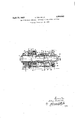
Other objects and advantages ofmy inven: tion will be set forth in thefollowing specification, in which reference is made to the accompanying drawing which is an axial vertical section through a variable speed gearing of the type specified, wherein the annular support for the C-shaped ring is made shorter and continuous, and the toothed wheel transmitting motion from the engine shaft to the gounter-shaft is arranged outside the gear Referring to the drawing 1 denotes the gear box through which are fitted the engine shaft 2 and the bell-shaped end of the transmission shaft 22.
The engine shaft 2 drives a C-shaped ring 8 having an internal set of teeth 7 meshing with the pinion 6 of the engine shaft and an external set of teeth 9 meshing with the internal I set of teeth 10 of the crown 11 carried by the sleeve 12 mounted on the engine shaft 2 by means of a bush bearing 13.
The C-shaped ring 8 is supported by an annular flange 14: excentrically projecting from the member 16 fixed to the front wall of the gear box 1 and coaxial with the engine shaft, said member housing the ball bearing 17 for the engine shaft 2. A set of rollers 15 are inserted between the C-shaped ring 8 and the annular flange end placed in the hollow of the C-shaped ring in the same plane as the sets of teeth 7 and 9.
The annular support 1116 is very short and requires no gap, through which the toothed wheels transmitting motion from the engine shaft to the counter-shaft may engage,,while such a gap was required in the construction according to the copending application. 1 k V The toothed wheel 5 keyed on the countershaft-3-issituated outsidethe gear box 1 and meshes with a toothed wheel keyed on a portion of the engine shaft 2 external to the gearbox. The wheels 4. and 5 are protected by the cover 36. v
The transmission shaft 22 carries a single bell .20 housing the bush bearing 23 in the sameplane as the roller bearing 86 mounted in the rear Wall of'the'gear box 1 and supporting in the usual manner the transmission shaft 22. A bush bearing 2Lis arranged \Vlthlll a sleeve 19 capable of axial displacement, but kept against rotation within the bell 20. Said sleeve 19 is provided with dog teeth 19a adaptedto alternately engage the teeth 12a. and 184;, respectively, of the sleeve 12 and crown 18 of the engine shaft 2; the dog teeth 19a-of the sleeve 19 being twice as high as the teeth 12a and 18a, because it .is necessaryfrom a constructional standpoint tomake the sleeve 12 with an innerdiameter equal to or larger than thatof the set of teeth 18a.
. For the same reason the bush bearingl3 is diametrically subdivided into two parts which are secured by screws 13a to the sleeve 12 and hold this latter against a shoulder on the shaft 2.
The sleeve 19 is slidably keyed to the bell 20'by means of teeth 206 on the bell engaging grooves 19?) on the sleeve. V
The bell-shaped end of the transmission shaft is provided with toothed crowns 28 and 30 with'which may alternatively engage the pinions 27 and 29 respectively, said pinions being rigidly connected together and mount-- edon the counter-shaft 3 for axial displace ment by means of the usual collar 31.
*The counter-shaft 3 is supportedin the usual manner by the front and rear wall of'the'casingl through ball bearings 32 and 33 respectively.
r The working of the above described va 7 riable speed gearing is as follows; supposingv the partsin .theidler position as shown in the dirawing,I movethe slidable pinions on the counter-shaft 3 to right hand until the pinion 27 engages the toothed crown 28 and obtain the first speed, then displace the slidable pinions to left hand for engaging the pinion 29 with the toothed crown 30 and obtain the second speed. For the third speed I bring the slidable pinions in idler position and displace the sleeve 19 to left hand until the teeth 19a engage the teeth 12d; the direct drive is obtained by bringing the teeth 19a of the sleeve 19 in mesh with the teeth 18a on the engine shaft.
What I claim is:
1. Variable speed gearing comprising, in combination with a box, a driving shaft and a driven shaft mounted in said box, one end of said driven shaft being in the shape of a bell, in which the driving shaft is co-aX- ially supported, an annular member traversed by the driving shaft and secured to the box excentrically with respect to said shafts, a C-shaped ring supported by said excentric annular member and having an inner set of teeth and an outer set of teeth, a pinion keyed on the driving shaft meshing with said internal set of teeth, a sleeve loosely mounted on said driving shaft, a set of internal teeth fast with said sleeve and meshing with said external set of teeth of the C-shaped ring, dog teeth on said sleeve and on said engine shaft, a sleeve movable in the bell-shaped end of the transmission shaft and provided with dog teeth that may be alternatively brought into gear with the dog teeth of the first mentioned sleeve and of said engine shaft, two toothed crowns on said bell, a counter-shaft, a toothed wheel on said countershaft meshing with a toothed wheel on the engine shaft arranged externally of said annular excentric member and pinions mounted for axial displacement but kept against rotation on said countershaft and that may be alternatively thrown into gear with the corresponding toothed crowns on said bell.
2. Variable speed gearing comprising, in combination with a box, a driving shaft and a driven shaft mounted in said box, one end of said driven shaft being in the shape of a bell, in which the driving shaft is co-axially supported, an annular member traversed by the driving shaft and secured to the box excentrically with respect to said shafts, a C-shaped ring, supported by said excentric annular member and having an inner set of teeth and an outer set of teeth, a pinion keyed on the driving shaft meshing. with said internal set of teeth, a sleeve loosely mounted on said driving shaft, a set of internal teeth fast with said sleeve and meshing with said external set of teeth of the C-shaped ring, dog teeth on said sleeve and on said engine shaft, a sleeve movable in the bell shaped end of the transmission shaft and provided with dog teeth that may be alternatively brought into gear with the dog teeth of the first mentioned sleeve and of said engine shaft, two toothed crowns on the bell, a counter-shaft, a toothed wheel on an ex tension of said counter-shaft external to the gear box, a toothed wheel on the engine shaft externally of the gear box and meshing with the toothed wheel on the counter-shaft, a casing for protecting said toothed wheel fixed .to the gear box and pinions mounted for ex ia-l displacement but kept against rotation on said countershaft'and that may be alternatively thrown into gear with the corresponding crowns on said bell.
In testimony that I claim the foregoing as my invention, I have signed my name. VITTORIO VALLETTA.
Priority Applications (1)
| Application Number | Priority Date | Filing Date | Title |
|---|---|---|---|
| US482839A US1854082A (en) | 1929-11-19 | 1930-09-18 | Variable speed gearing, particularly for motor vehicles |
Applications Claiming Priority (2)
| Application Number | Priority Date | Filing Date | Title |
|---|---|---|---|
| US408292A US1796067A (en) | 1928-11-24 | 1929-11-19 | Variable-speed gearing, particularly for motor vehicles |
| US482839A US1854082A (en) | 1929-11-19 | 1930-09-18 | Variable speed gearing, particularly for motor vehicles |
Publications (1)
| Publication Number | Publication Date |
|---|---|
| US1854082A true US1854082A (en) | 1932-04-12 |
Family
ID=27020224
Family Applications (1)
| Application Number | Title | Priority Date | Filing Date |
|---|---|---|---|
| US482839A Expired - Lifetime US1854082A (en) | 1929-11-19 | 1930-09-18 | Variable speed gearing, particularly for motor vehicles |
Country Status (1)
| Country | Link |
|---|---|
| US (1) | US1854082A (en) |
Cited By (4)
| Publication number | Priority date | Publication date | Assignee | Title |
|---|---|---|---|---|
| US3534607A (en) * | 1968-09-26 | 1970-10-20 | Int Harvester Co | Sliding tube change-speed transmission |
| US8668613B1 (en) * | 2012-01-10 | 2014-03-11 | The United States Of America As Represented By The Administrator Of National Aeronautics And Space Administration | Offset compound gear inline two-speed drive |
| US20150102655A1 (en) * | 2013-10-11 | 2015-04-16 | Delbert Tesar | Gear train and clutch designs for multi-speed hub drives |
| US20150292601A1 (en) * | 2013-10-11 | 2015-10-15 | Delbert Tesar | Standardized gear train modules for multi-speed hub drive wheels |
-
1930
- 1930-09-18 US US482839A patent/US1854082A/en not_active Expired - Lifetime
Cited By (5)
| Publication number | Priority date | Publication date | Assignee | Title |
|---|---|---|---|---|
| US3534607A (en) * | 1968-09-26 | 1970-10-20 | Int Harvester Co | Sliding tube change-speed transmission |
| US8668613B1 (en) * | 2012-01-10 | 2014-03-11 | The United States Of America As Represented By The Administrator Of National Aeronautics And Space Administration | Offset compound gear inline two-speed drive |
| US20150102655A1 (en) * | 2013-10-11 | 2015-04-16 | Delbert Tesar | Gear train and clutch designs for multi-speed hub drives |
| US20150292601A1 (en) * | 2013-10-11 | 2015-10-15 | Delbert Tesar | Standardized gear train modules for multi-speed hub drive wheels |
| US9365105B2 (en) * | 2013-10-11 | 2016-06-14 | Delbert Tesar | Gear train and clutch designs for multi-speed hub drives |
Similar Documents
| Publication | Publication Date | Title |
|---|---|---|
| US4141424A (en) | Transmission for tractors | |
| ES346725A1 (en) | Drive for motor vehicles | |
| US1854082A (en) | Variable speed gearing, particularly for motor vehicles | |
| US2878692A (en) | Variable transmission | |
| US1258883A (en) | Power-transmission mechanism. | |
| US1077519A (en) | Reversing mechanism. | |
| US1459026A (en) | Transmission mechanism | |
| US1479292A (en) | Change-speed mechanism | |
| US1511156A (en) | Transmission mechanism | |
| US2035054A (en) | Reversing gear comprising pressure oil operated control couplings, particularly for ships' drives | |
| US1797577A (en) | Motor vehicle | |
| US1802482A (en) | Overspeed transmission | |
| US953992A (en) | Transmission-gearing. | |
| US1843071A (en) | Overspeed rear axle | |
| US1557628A (en) | Power take-off | |
| US1169073A (en) | Power-transmission device. | |
| GB190308203A (en) | Improvements in Speed Changing Mechanism Suitable for Motor Road Vehicles. | |
| US1797576A (en) | Power-transmitting mechanism | |
| US1842636A (en) | Variable speed gearing, particularly for motor vehicles | |
| US1365217A (en) | Change-speed gearing | |
| US1379675A (en) | Changeable gear for automobiles | |
| GB773448A (en) | Improvements relating to change-speed gears for tractors | |
| US1396526A (en) | Transmission-gearing | |
| SU372094A1 (en) | TRANSMISSION TRANSPORT MACHINE | |
| US1222097A (en) | Differential or compensating gearing. |