US1854079A - Brick mold - Google Patents
Brick mold Download PDFInfo
- Publication number
- US1854079A US1854079A US374597A US37459729A US1854079A US 1854079 A US1854079 A US 1854079A US 374597 A US374597 A US 374597A US 37459729 A US37459729 A US 37459729A US 1854079 A US1854079 A US 1854079A
- Authority
- US
- United States
- Prior art keywords
- mold
- members
- blocks
- brick
- straps
- Prior art date
- Legal status (The legal status is an assumption and is not a legal conclusion. Google has not performed a legal analysis and makes no representation as to the accuracy of the status listed.)
- Expired - Lifetime
Links
- 239000011449 brick Substances 0.000 title description 9
- 238000005192 partition Methods 0.000 description 10
- 229910000831 Steel Inorganic materials 0.000 description 5
- 239000010959 steel Substances 0.000 description 5
- 238000010276 construction Methods 0.000 description 4
- 239000000463 material Substances 0.000 description 4
- 239000002023 wood Substances 0.000 description 4
- 230000002596 correlated effect Effects 0.000 description 1
- 239000002184 metal Substances 0.000 description 1
- 238000000034 method Methods 0.000 description 1
Images

Classifications
-
- B—PERFORMING OPERATIONS; TRANSPORTING
- B28—WORKING CEMENT, CLAY, OR STONE
- B28B—SHAPING CLAY OR OTHER CERAMIC COMPOSITIONS; SHAPING SLAG; SHAPING MIXTURES CONTAINING CEMENTITIOUS MATERIAL, e.g. PLASTER
- B28B7/00—Moulds; Cores; Mandrels
- B28B7/36—Linings or coatings, e.g. removable, absorbent linings, permanent anti-stick coatings; Linings becoming a non-permanent layer of the moulded article
- B28B7/366—Replaceable lining plates for press mould
Definitions
- rIhis invention has to do with brick molds for use principally in automatic. brick making machines in which the molds are delivered from the expressing die to a bumping mechanismand thence to an inverting device.
- the bumper delivers alternate impacts to the ends of the mold to free the material in the several molds cavities from its adhesion to the wall thereof so that when inverted the several brick forms will drop out freely onto a plate which is carried away to the succeeding stages of the brick-making process.
- the object of this invention is to improve upon existing molds by making it less often necessary to replace theentire mold, by providing a stronger construction of mold, and by lessening the cost of renewing the parts of the mold which afford the surfaces directly in contact with the plastic.
- rlhe characteristic feature of the invention is the use of a skeleton frame of steel or other strong metal with inserts of wood, or other material suitable for direct contact with the plastic material, forming the mold cavities.
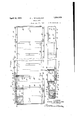
- Figure 1 is a plan view of a mold made according to this invention, a part being broken away to show the interior construction.
- Figure 2 is a side elevation of the same mold with a part broken away to show the interior.
- Figure 3 is an end elevation.
- Figure 4 is a view in section on the line 4-4 of Figure 1.
- Figures 5 and 6 are respectively a plan and an elevation of an insert of the type forming the end walls of the mold cavities.
- Figure 7 is a perspective view of the bumper block that is secured to the end of the mold.
- Figure 8 is a perspective view of an insert of the type used to form the transverse partif tions of the mold between every two cavities and the outer side wall of each end cavity.
- Figure 9 is a perspective view of an insert used to form the bottom of each cavityo the mold.
- the skeleton frame consists of two side members 10, 11 of steel, rectangular in cross section and of about the depth of the mold'itself. These two side members are secured at their ends to two steel end members 12, 13 which are of .the shape-of an H invertical cross section and of I shape in horizontal section, being closedV at their sides 14, ,15 by webs integral with the top and bottom webs 16, 17 and with the central transverse vertical web 18. The side members are held to the end pieces by bolts 19 taking into the side webs 14,15. Y'
- the ends of these end members are open and that one which faces outward receives a bumper block 2O of wood. If desired the inner end may be partially closed by a web 21.
- This bumper block is tapered on its ends and top and bottom sides and has an opening 22 through it for a bolt or rivet 23, smaller than the opening, which extends between the Vtop and bottom webs 16, 17 of the-end piece.
- the block extends in far enough to engage the cross-web 18.
- Each end member has a shoulder 25, along the side margins ot the top and bottom webs, these shoulders being set back from the plane of the top and bottom for the purpose of accommodating the ends of straps which will be described vhereinafter.
- Y Y y' The 'mold is completed by an arrangement of wood inserts correlated in shape with one another so as to'interlock and are held in the frame to form the mold cavities. rIhe bottoms of the cavities are formed by separate blocks 30 ( Figure 9), one for each cavity,
- Each j such block has a main portion 31 that is rectangular in section and in plan and has projections 32 at its ends that are of the same width ,as the body ⁇ portions but of less thickness.
- VArwshallow slot 33 extends along one face 34 for the full length of 'the body por- .tion and in depth is equal to the amount of l the face set-back of the end projections from These bottom pieces are placed in the frame with the slotted face 34 facing outwardly.
- a steel strap 35 rests in each slot and is held to the body portion 31 by screws 36. A space is left between every two bottom pieces and between the end pieces and the inner faces of the end members 10, 11.
- the end walls of the cavities are provided by small, relatively thin, blocks 4l() which rest on the projections 32 at the ends of the bottom pieces and each is held between the inner face of the side member against which it liesand the lateral face 37 of the main body portion 3l above the projection 32 on which it rests.
- the side edges l1 of these blocks are sloped inwardly from bottom to topwhile their top faces l2 lie flush with the upper edges of the side members.
- the cavities' are completed by transverse partition pieces having end projections 51 narrower than the main part 52 and tapered on their side fac-es 53 from top to bottom so that they fit the converging adjacent edges ll of the end blocks 40, rlhe main part of each partitionis of greater thickness than the spacing between the end blocks which results in an engagement between the end faces 54 of this main part and the faces of the end blocks near their edges. ln this way the end blocks are further locked against the side members while the partitions themselves are held against sidewise movement by the fit of their tapered projections 52 between the end blocks e0. y
- a strap 55 is bolt-ed to the top edge of each side member and is wide enough to overlie the end blocks and the projections 52 on the partitions.
- An additional bracing is provided by a series of cross straps 56 on the top edge of each partitiomthese cross straps being held to the partitions by bolts 57 extending through the partitions from the bottom and headed over in recesses in the outer surfaces of the straps to lie Hush therewith.
- lug 58 wider at its outer end than at its inner end and integral with the straps.
- Suitably conforming notches in the side straps 55 receive these lugs,
- the top and bottom sid-e straps 55, 6 0 are off-set toward each other to Vform the extensions which rest on the shoulders V25 along the edges of the end members 12, 13.
- the steel frame is strong enough to maintain its shape for a much longer period of use than is a wooden mold.
- the replacement of the part-s which engage the plastic material is readily accomplished. lith the existing molds, when the surfaces engaging the plastic require replacement, it is necessary to discard the entire mold whereas the construction according to this invention requires only the renewal of the wood insert blocks 30, 40, 50.
- a brick mold for an automatic brick making machine said mold having rigid metallic side members, a pair of rigid metallic end members joining said side members, a plurality of replaceable wooden lining embers between said side and end members forming the mold cavities, and bumping blocks removable secured within said end members.
- a brick mold for an automatic brick making machine said mold having rigid metallic side members, a pair of rigid metallic end members joining said side members, a plurality of transverse wooden partitions and a plurality of wooden bottom and end members located between said metallic side and end members and forming the mold cavities, said wooden members and partitions being replaceable, two of said transverse partitions abutting said metallic end members while the remaining partitions each separate one mold cavity from another, and bumping blocks removably secured in said end members.
Landscapes
- Engineering & Computer Science (AREA)
- Manufacturing & Machinery (AREA)
- Chemical & Material Sciences (AREA)
- Ceramic Engineering (AREA)
- Mechanical Engineering (AREA)
- Forms Removed On Construction Sites Or Auxiliary Members Thereof (AREA)
Description
April 12, 1932. 0.'.1. STRICKLAND BRICK MOLD l 2 Shets-neet Filed June 28, 1929 INVENTOR DAVID .J. ST RICKL AND y 71111 aifarneyw www Patented Apr. 12, 1932 PATENT oI-glucE :DAVID J'. STRICKLAND, 0F BEACON, NEW YORK, ASSIGNOR T0 HENRY IOXTELI.:l
i l RAMSDELL, TRUSTEE, OF NEWBUBGH, NEW YORK BRICK MOLD Application led June 28,
rIhis invention has to do with brick molds for use principally in automatic. brick making machines in which the molds are delivered from the expressing die to a bumping mechanismand thence to an inverting device. The bumper delivers alternate impacts to the ends of the mold to free the material in the several molds cavities from its adhesion to the wall thereof so that when inverted the several brick forms will drop out freely onto a plate which is carried away to the succeeding stages of the brick-making process.
The object of this invention is to improve upon existing molds by making it less often necessary to replace theentire mold, by providing a stronger construction of mold, and by lessening the cost of renewing the parts of the mold which afford the surfaces directly in contact with the plastic. rlhe characteristic feature of the invention is the use of a skeleton frame of steel or other strong metal with inserts of wood, or other material suitable for direct contact with the plastic material, forming the mold cavities.
In the accompanyingV drawings- Figure 1 is a plan view of a mold made according to this invention, a part being broken away to show the interior construction.
Figure 2 is a side elevation of the same mold with a part broken away to show the interior.
Figure 3 is an end elevation.
Figure 4 is a view in section on the line 4-4 of Figure 1.
Figures 5 and 6 are respectively a plan and an elevation of an insert of the type forming the end walls of the mold cavities.
Figure 7 is a perspective view of the bumper block that is secured to the end of the mold.
Figure 8 is a perspective view of an insert of the type used to form the transverse partif tions of the mold between every two cavities and the outer side wall of each end cavity.
Figure 9 is a perspective view of an insert used to form the bottom of each cavityo the mold.
of body portion 31. 1
1929. Serial N0.v374,597.
In the form of mold, built according to this invention, as I prefer to make it, the skeleton frame consists of two side members 10, 11 of steel, rectangular in cross section and of about the depth of the mold'itself. These two side members are secured at their ends to two steel end members 12, 13 which are of .the shape-of an H invertical cross section and of I shape in horizontal section, being closedV at their sides 14, ,15 by webs integral with the top and bottom webs 16, 17 and with the central transverse vertical web 18. The side members are held to the end pieces by bolts 19 taking into the side webs 14,15. Y'
The ends of these end members -are open and that one which faces outward receives a bumper block 2O of wood. If desired the inner end may be partially closed by a web 21. This bumper block is tapered on its ends and top and bottom sides and has an opening 22 through it for a bolt or rivet 23, smaller than the opening, which extends between the Vtop and bottom webs 16, 17 of the-end piece.
The block extends in far enough to engage the cross-web 18. Each end member has a shoulder 25, along the side margins ot the top and bottom webs, these shoulders being set back from the plane of the top and bottom for the purpose of accommodating the ends of straps which will be described vhereinafter.Y Y y' The 'mold is completed by an arrangement of wood inserts correlated in shape with one another so as to'interlock and are held in the frame to form the mold cavities. rIhe bottoms of the cavities are formed by separate blocks 30 (Figure 9), one for each cavity,
equal in width to the width of the cavity and long enough over-all to reach between the side members'10, 11v of the frame. Each j such block has a main portion 31 that is rectangular in section and in plan and has projections 32 at its ends that are of the same width ,as the body` portions but of less thickness. VArwshallow slot 33 extends along one face 34 for the full length of 'the body por- .tion and in depth is equal to the amount of l the face set-back of the end projections from These bottom pieces are placed in the frame with the slotted face 34 facing outwardly. A steel strap 35 rests in each slot and is held to the body portion 31 by screws 36. A space is left between every two bottom pieces and between the end pieces and the inner faces of the end members 10, 11.
The end walls of the cavities are provided by small, relatively thin, blocks 4l() which rest on the projections 32 at the ends of the bottom pieces and each is held between the inner face of the side member against which it liesand the lateral face 37 of the main body portion 3l above the projection 32 on which it rests. The side edges l1 of these blocks are sloped inwardly from bottom to topwhile their top faces l2 lie flush with the upper edges of the side members.
The cavities' are completed by transverse partition pieces having end projections 51 narrower than the main part 52 and tapered on their side fac-es 53 from top to bottom so that they fit the converging adjacent edges ll of the end blocks 40, rlhe main part of each partitionis of greater thickness than the spacing between the end blocks which results in an engagement between the end faces 54 of this main part and the faces of the end blocks near their edges. ln this way the end blocks are further locked against the side members while the partitions themselves are held against sidewise movement by the fit of their tapered projections 52 between the end blocks e0. y
To hold the partitions, and hence the end blocks, from movement out of the frame, a strap 55 is bolt-ed to the top edge of each side member and is wide enough to overlie the end blocks and the projections 52 on the partitions. An additional bracing is provided by a series of cross straps 56 on the top edge of each partitiomthese cross straps being held to the partitions by bolts 57 extending through the partitions from the bottom and headed over in recesses in the outer surfaces of the straps to lie Hush therewith. At the end of each strap is a. lug 58 wider at its outer end than at its inner end and integral with the straps. Suitably conforming notches in the side straps 55 receive these lugs,
providing a dovetailed joint.
On the under sid-e, there are side straps 60 bolted to the side members 10, 11 and notched as the top straps are to receive lugs 61, like the lugs 58 ust described,'on the ends of the cross straps 35 which are bolted to the bottom blocks 30.
At the ends of the mold,the top and bottom sid-e straps 55, 6 0 are off-set toward each other to Vform the extensions which rest on the shoulders V25 along the edges of the end members 12, 13.
t will be apparent that this construction has several important advantages overthe wooden mold, with lsome strap bracing, in
common use. The steel frame is strong enough to maintain its shape for a much longer period of use than is a wooden mold. The replacement of the part-s which engage the plastic material is readily accomplished. lith the existing molds, when the surfaces engaging the plastic require replacement, it is necessary to discard the entire mold whereas the construction according to this invention requires only the renewal of the wood insert blocks 30, 40, 50.
l claim- 1. A brick mold for an automatic brick making machine, said mold having rigid metallic side members, a pair of rigid metallic end members joining said side members, a plurality of replaceable wooden lining embers between said side and end members forming the mold cavities, and bumping blocks removable secured within said end members.
2. A brick mold for an automatic brick making machine, said mold having rigid metallic side members, a pair of rigid metallic end members joining said side members, a plurality of transverse wooden partitions and a plurality of wooden bottom and end members located between said metallic side and end members and forming the mold cavities, said wooden members and partitions being replaceable, two of said transverse partitions abutting said metallic end members while the remaining partitions each separate one mold cavity from another, and bumping blocks removably secured in said end members.
In testimony whereof I have signed my name to this specification.
DAVID J. STRICKLANI).
Priority Applications (1)
| Application Number | Priority Date | Filing Date | Title |
|---|---|---|---|
| US374597A US1854079A (en) | 1929-06-28 | 1929-06-28 | Brick mold |
Applications Claiming Priority (1)
| Application Number | Priority Date | Filing Date | Title |
|---|---|---|---|
| US374597A US1854079A (en) | 1929-06-28 | 1929-06-28 | Brick mold |
Publications (1)
| Publication Number | Publication Date |
|---|---|
| US1854079A true US1854079A (en) | 1932-04-12 |
Family
ID=23477506
Family Applications (1)
| Application Number | Title | Priority Date | Filing Date |
|---|---|---|---|
| US374597A Expired - Lifetime US1854079A (en) | 1929-06-28 | 1929-06-28 | Brick mold |
Country Status (1)
| Country | Link |
|---|---|
| US (1) | US1854079A (en) |
Cited By (1)
| Publication number | Priority date | Publication date | Assignee | Title |
|---|---|---|---|---|
| US4343453A (en) * | 1980-04-02 | 1982-08-10 | Rampf Kg Formen Gmbh & Co. | Mould for producing concrete mouldings |
-
1929
- 1929-06-28 US US374597A patent/US1854079A/en not_active Expired - Lifetime
Cited By (1)
| Publication number | Priority date | Publication date | Assignee | Title |
|---|---|---|---|---|
| US4343453A (en) * | 1980-04-02 | 1982-08-10 | Rampf Kg Formen Gmbh & Co. | Mould for producing concrete mouldings |
Similar Documents
| Publication | Publication Date | Title |
|---|---|---|
| US1854079A (en) | Brick mold | |
| US1523710A (en) | Faceplate | |
| US1235858A (en) | Block-mold. | |
| US2522603A (en) | Multiple block mold | |
| US1774547A (en) | Mold | |
| US1655023A (en) | Cement-molding apparatus | |
| US2440582A (en) | Building block form | |
| US2101992A (en) | Method for manufacturing composite vitreous tile and concrete staves | |
| US692006A (en) | Brick-mold. | |
| US973323A (en) | Mold for making hollow building-blocks. | |
| US790507A (en) | Mold for cement blocks. | |
| US1675443A (en) | Concrete-spreader mold | |
| US382678A (en) | Confectioners mold | |
| US1041540A (en) | Spring filler or cut-off for use in connection with molding machinery. | |
| US1692913A (en) | Mold | |
| US765907A (en) | Mold for brick-making machines. | |
| US1649199A (en) | Mold chill | |
| US1756473A (en) | Form and mold | |
| US2798473A (en) | Saw blade for stone cutting machine | |
| US1421006A (en) | Block mold | |
| US573455A (en) | Sectional brick-mold | |
| US978035A (en) | Mold for forming plastic articles. | |
| US1431631A (en) | Rail tie | |
| US749781A (en) | Mold for brick-machines | |
| US2296187A (en) | Form for precasting interrelated concrete units |