US1854070A - Cooler - Google Patents
Cooler Download PDFInfo
- Publication number
- US1854070A US1854070A US442913A US44291330A US1854070A US 1854070 A US1854070 A US 1854070A US 442913 A US442913 A US 442913A US 44291330 A US44291330 A US 44291330A US 1854070 A US1854070 A US 1854070A
- Authority
- US
- United States
- Prior art keywords
- cover
- container
- housing
- door
- food
- Prior art date
- Legal status (The legal status is an assumption and is not a legal conclusion. Google has not performed a legal analysis and makes no representation as to the accuracy of the status listed.)
- Expired - Lifetime
Links
- 235000000396 iron Nutrition 0.000 description 4
- 235000013305 food Nutrition 0.000 description 3
- 239000002689 soil Substances 0.000 description 3
- XEEYBQQBJWHFJM-UHFFFAOYSA-N Iron Chemical compound [Fe] XEEYBQQBJWHFJM-UHFFFAOYSA-N 0.000 description 2
- 210000005069 ears Anatomy 0.000 description 2
- 230000003028 elevating effect Effects 0.000 description 2
- 239000002184 metal Substances 0.000 description 2
- 229910052751 metal Inorganic materials 0.000 description 2
- 239000004576 sand Substances 0.000 description 2
- 241000238631 Hexapoda Species 0.000 description 1
- 241000283984 Rodentia Species 0.000 description 1
- 229910000746 Structural steel Inorganic materials 0.000 description 1
- 230000006835 compression Effects 0.000 description 1
- 238000007906 compression Methods 0.000 description 1
- 238000010276 construction Methods 0.000 description 1
- 230000007797 corrosion Effects 0.000 description 1
- 238000005260 corrosion Methods 0.000 description 1
- 229930192878 garvin Natural products 0.000 description 1
- 229910052742 iron Inorganic materials 0.000 description 1
- 230000002093 peripheral effect Effects 0.000 description 1
- XLYOFNOQVPJJNP-UHFFFAOYSA-N water Substances O XLYOFNOQVPJJNP-UHFFFAOYSA-N 0.000 description 1
Images
Classifications
-
- A—HUMAN NECESSITIES
- A47—FURNITURE; DOMESTIC ARTICLES OR APPLIANCES; COFFEE MILLS; SPICE MILLS; SUCTION CLEANERS IN GENERAL
- A47J—KITCHEN EQUIPMENT; COFFEE MILLS; SPICE MILLS; APPARATUS FOR MAKING BEVERAGES
- A47J47/00—Kitchen containers, stands or the like, not provided for in other groups of this subclass; Cutting-boards, e.g. for bread
- A47J47/02—Closed containers for foodstuffs
Definitions
- Another object of the invention is to providev means whereby a low natural tempera-- ture maybe taken advantage of in preserving l@ food-stuffs or products and, in this connection7 the'invention contemplates the storing of food-stuffs in a container which is normally positoned in the bottom of Ya closed housing which is embedded in the ground to Vsuch 'Tl-3 a depth as to be kept at asuiiiciently low temperature ⁇ to maintain the freshness of the food-stuffs or products, means being provided whereby the container may be Vbrought to ground level so that the contents thereof may be removed Afor consumption or the supply replenished.l
- Figure 2 is a vertical sectional view through the container of the apparatus.
- Figure 3 is a horizontal sectional view taken substantially on the line 3-3 of Figure 1 looking in the direction indicated by the arrows.
- Figure 4 is a similar view on the line 4-4 of Figure 1 looking in the direction indicated by the arrows.
- Figure 5 is a fragmentary view in elevation illustrating a means for holding thel door of the container in closed position.
- the apparatus comprises a housing 1 which is of hollow cylindrical form and whichmay bev of galvanized sheet metal, to avoid corrosion, and this hou-sing is open at its upper end and-'closed at its lower end by a bottom 2 55 and in installing the apparatus, the housing is embedded in the soil to extend to a depth considerably below the frost zone of the soil.
- a container Arranged within the housing is the contain-er for the food-stuffs to be stored and this container, which is indicated in general by the numeral 3, is likewise preferably of sheet metal, such for example as galvanized iron,
- the same ⁇ comprises a hollow cylindrical body 4 closed by a bottom 6 and closed at its 65 upper end by atop closure 7.
- the body 4 of the container is formed with an opening and an arcuate door 8 which constitutes a movable section of the body 4, is hingedly mounted at oneside as at 9 upon the body 70 Y l preferably by strap hinges 1() which extend about the outer side of the door and other hinged members 11 which are mounted upon the body at that side of the opening therein at which the door is hinged, a rod 12 being 75 fitted through the hinged members to connect the same.V ln order that the container door may be kept closed, a latch means is provided which will now be described.
- the other end of the bolt is formed with a hook bill indicated bythe numeral 17 which is engageable with a keeper hook 18 formed at one end of an attaching member 19 which is mounted upon the body ofthe casing at the 'other side of the door opening therein.
- a hook bill indicated bythe numeral 17 which is engageable with a keeper hook 18 formed at one end of an attaching member 19 which is mounted upon the body ofthe casing at the 'other side of the door opening therein.
- rlhe end of the hook bill 17 is preferably provided with a rounded head 20 whereby pressure maybe exerted thereagainst to shift the latchmemb-er 13 bodily against thev tension of the spring 16 to disengage its bill 17 from the keeper hook 18.
- angle irons 21 are disposed against the outer side of the wall of the container at equally spaced intervals in the circumference thereof and secured in place by rivets or other suitable fastening ⁇ elements 22 and the other wings of the angle irons are overturned upon them selves as indicated by the numeral 23 and theirbends or folds engage against the inner surface of the wall of the housing 1.
- rods 2e are connected at their lower ends as at 25 to the upper ends of the angle irons 21 and it will be observed at this point and particularly by reference to Figure 1 that the lower ends of these angle irons project below the bottom 6 and restupon the bottom 2. of the housing 1.
- the upper ends of the .rods 24C are thread-ed and fit through openings formedk in Va circular pan member 26 which is disposed against the under side of a cover or lid 27, nuts 29 being threaded upon the upper. ends of the rods 24 and housed within the pan member.
- the cover 27 is of circular form and carries another peripheral liange as indicated by the numeral 28 to adapt it to fit snugly over the upper end of the body of the housing 1.
- An eye-bolt QO has its shank fitted thru alined openings in the cover 27 and the member 26 and a nut 31 is threaded onto the lower end of the shank. ⁇ At this point it will be evident that, inasmuch as the eye 30 engages i the upper side of the cover 27, tightening of the bolt 31 will serve to secure the member 2G securely in place against the under side of the cover 27.
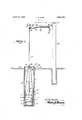
- a cable 32 is connected at one ond to the ⁇ eye BOVand is led upwardly and over a pulley mounted between a pair of angle iron bars 34 which are connected by hangerlinks 35 and braces 86 with anA arm 37 which extends laterally from the upper end of a post 38, the lower end of which post is embedded in the soil.
- a counter weight 39 is connected to the other end of the cable and serves, to a greater or less degree, to counter-balance the weight of the container and the products contained therein.
- the cover 27 serves to seal the top of the housing 1 so that insects or rodents cannot enter the housing nor will rain water enter the housing. It will further be understood that the points of the weight 39 may be varied or other weights may be connected with the upper end of the cable 32, if desired.
Description
Filed April 9, 1930 2 ,Shee'lLs-*SheefI l 5 ,1, y i 5 [j Q5 NvENToR 6 l i i ATTORNEY April 12 1932. J, M4 SAND 1,854,070
COOLER Filed April 9, 1930 2 sheets-sheet '2 'Z' ff 7 l Hi 0i Il: l r` I I' l' l I I| l i x J/ l |l l 4f' el j 1 1 1| i '4 0F W) U 2 M 6- zz I ,l if 1 if i j! Y z5 9* if j@ Z5 f5 y j 1% 6 I Mdmvem'on 7 I@ BY V30 within the scope of the claims;
Patented VApr. 12, 1932 NTED STATES JOHN M. SAND, or GARVIN, MINNESOTA COOLER.
Application filed April 9, 1930. Serial Nol 442,913.
' 5 any other refrigerating medium which must be'purchased. y
' Another object of the invention is to providev means whereby a low natural tempera-- ture maybe taken advantage of in preserving l@ food-stuffs or products and, in this connection7 the'invention contemplates the storing of food-stuffs in a container which is normally positoned in the bottom of Ya closed housing which is embedded in the ground to Vsuch 'Tl-3 a depth as to be kept at asuiiiciently low temperature `to maintain the freshness of the food-stuffs or products, means being provided whereby the container may be Vbrought to ground level so that the contents thereof may be removed Afor consumption or the supply replenished.l
rlhis invention also consists incertain other features of construction and in the combination and arrangement of the several parts to be hereinafter fully described, illustrated in the accompanying drawings, and specifically pointed out in the appended claims, it being understood of course that i minor changes maybe made so longl as they fall In' describing my invention in detail, reference will be had to the accompanying drawings, wherein like characters denote like or corresponding parts throughout the several views, and in which Figure l is an elevational view partly in section and illustrating the apparatus embodying the invention. Y
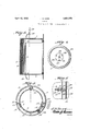
Figure 2 is a vertical sectional view through the container of the apparatus.
Figure 3 is a horizontal sectional view taken substantially on the line 3-3 of Figure 1 looking in the direction indicated by the arrows.
Figure 4 is a similar view on the line 4-4 of Figure 1 looking in the direction indicated by the arrows.
Figure 5 is a fragmentary view in elevation illustrating a means for holding thel door of the container in closed position.
The apparatus comprises a housing 1 which is of hollow cylindrical form and whichmay bev of galvanized sheet metal, to avoid corrosion, and this hou-sing is open at its upper end and-'closed at its lower end by a bottom 2 55 and in installing the apparatus, the housing is embedded in the soil to extend to a depth considerably below the frost zone of the soil.. Arranged within the housing is the contain-er for the food-stuffs to be stored and this container, which is indicated in general by the numeral 3, is likewise preferably of sheet metal, such for example as galvanized iron,
and the same `comprises a hollow cylindrical body 4 closed by a bottom 6 and closed at its 65 upper end by atop closure 7. At one side, the body 4 of the container is formed with an opening and an arcuate door 8 which constitutes a movable section of the body 4, is hingedly mounted at oneside as at 9 upon the body 70 Y l preferably by strap hinges 1() which extend about the outer side of the door and other hinged members 11 which are mounted upon the body at that side of the opening therein at which the door is hinged, a rod 12 being 75 fitted through the hinged members to connect the same.V ln order that the container door may be kept closed, a latch means is provided which will now be described.
The latchrmeans referred to above` com- Vprises a boltmember which is indicated by the numeral 18 and is slidably mounted in the spaced ears of a bracket member 14 which is secured upon the outer side of the door at the free side thereof, a nut 15 being fitted 85 to Vone end of the boltl and a compression spring 16 being fitted upon this end of the bolt and bearing between the nut and one of the ears 14. 9
' The other end of the bolt is formed with a hook bill indicated bythe numeral 17 which is engageable with a keeper hook 18 formed at one end of an attaching member 19 which is mounted upon the body ofthe casing at the 'other side of the door opening therein. rlhe end of the hook bill 17 is preferably provided with a rounded head 20 whereby pressure maybe exerted thereagainst to shift the latchmemb-er 13 bodily against thev tension of the spring 16 to disengage its bill 17 from the keeper hook 18.
In order that the container body may be supported with its bottom elevated above the bottom 2 of the housing 1 and its Wall l spaced from the wall of the housing, angle irons 21 are disposed against the outer side of the wall of the container at equally spaced intervals in the circumference thereof and secured in place by rivets or other suitable fastening` elements 22 and the other wings of the angle irons are overturned upon them selves as indicated by the numeral 23 and theirbends or folds engage against the inner surface of the wall of the housing 1.
In order that access may be gained to the container by elevating the same to the ground level, rods 2e are connected at their lower ends as at 25 to the upper ends of the angle irons 21 and it will be observed at this point and particularly by reference to Figure 1 that the lower ends of these angle irons project below the bottom 6 and restupon the bottom 2. of the housing 1. The upper ends of the .rods 24C are thread-ed and fit through openings formedk in Va circular pan member 26 which is disposed against the under side of a cover or lid 27, nuts 29 being threaded upon the upper. ends of the rods 24 and housed within the pan member. The cover 27 is of circular form and carries another peripheral liange as indicated by the numeral 28 to adapt it to fit snugly over the upper end of the body of the housing 1.
An eye-bolt QO has its shank fitted thru alined openings in the cover 27 and the member 26 and a nut 31 is threaded onto the lower end of the shank.` At this point it will be evident that, inasmuch as the eye 30 engages i the upper side of the cover 27, tightening of the bolt 31 will serve to secure the member 2G securely in place against the under side of the cover 27. A cable 32 is connected at one ond to the `eye BOVand is led upwardly and over a pulley mounted between a pair of angle iron bars 34 which are connected by hangerlinks 35 and braces 86 with anA arm 37 which extends laterally from the upper end of a post 38, the lower end of which post is embedded in the soil. A counter weight 39 is connected to the other end of the cable and serves, to a greater or less degree, to counter-balance the weight of the container and the products contained therein.
It will now be evident that by pulling upwardly upon the cable 32, an upward pull will be exerted upon the rods 24 and the cover 27 thus dislodging and elevating the cover and leiiecting an upward pull upon the angle bars 21 so as to cause upward movement of the container 3 and, as soon as the container has been brought to the ground surface, the door 8 may be opened by pressure against theiinger knob'20 and the door swung to open aosition and access Gained to the food roducts within the container. After the desired food products have been removed, they may be replenished by introduction of similar products into the container and likewise a further supply of any food product or commodity may be at such time introduced into the container.
It will be evident that the cover 27 serves to seal the top of the housing 1 so that insects or rodents cannot enter the housing nor will rain water enter the housing. It will further be understood that the points of the weight 39 may be varied or other weights may be connected with the upper end of the cable 32, if desired.
`What I claim is 1. The combination of a cylindrical body adapted to be confined beneath the surface of the ground and opening upwardly therethrough, a post at one side of said body and having an arm overhanging the latter, hangers carried by the arms, a receptacle receivable in the body, a cover for the open end of said body, rods connected with the cover and with said receptacle to suspend the latter from the cover, guide pulleys carried by the hangers, and a weighted cable trained over the guide pulleys and having connection centrally with the cover.
2. The combination of a cylindrical body adapted to be confined beneath the surface of the ground and opening upwardly therethrough, a post at one side of said body and having an arm overhanging the latter, hangers carried by the arm, a receptacle receivable in the body, a cover for the open end of said body, rods connected with the cover and with said receptacle to suspend the latter from the cover, guide pulleys carried by the hangers, and a weighted cable trained over the guide pulleys and having connection centrally with the cover, the said rods being of a length to permit the receptacle to be brought to rest in the body when the cover is engaged on the open end of the latter.
In testimony whereof I aHiX my signature.
JOHN M. SAND.
ist
Priority Applications (1)
| Application Number | Priority Date | Filing Date | Title |
|---|---|---|---|
| US442913A US1854070A (en) | 1930-04-09 | 1930-04-09 | Cooler |
Applications Claiming Priority (1)
| Application Number | Priority Date | Filing Date | Title |
|---|---|---|---|
| US442913A US1854070A (en) | 1930-04-09 | 1930-04-09 | Cooler |
Publications (1)
| Publication Number | Publication Date |
|---|---|
| US1854070A true US1854070A (en) | 1932-04-12 |
Family
ID=23758665
Family Applications (1)
| Application Number | Title | Priority Date | Filing Date |
|---|---|---|---|
| US442913A Expired - Lifetime US1854070A (en) | 1930-04-09 | 1930-04-09 | Cooler |
Country Status (1)
| Country | Link |
|---|---|
| US (1) | US1854070A (en) |
-
1930
- 1930-04-09 US US442913A patent/US1854070A/en not_active Expired - Lifetime
Similar Documents
| Publication | Publication Date | Title |
|---|---|---|
| US1854070A (en) | Cooler | |
| US2077208A (en) | Container | |
| US1975543A (en) | Tie rack | |
| US1186418A (en) | Freezer minnow-bucket. | |
| US2838264A (en) | Waste can holder | |
| US2707075A (en) | Door controlled signal for mail box | |
| US1286664A (en) | Door-support. | |
| US2298577A (en) | Holder for ice cream containers | |
| US2995409A (en) | Tray support bracket | |
| KR200496768Y1 (en) | Feeder for parrot and cage having it | |
| US2172123A (en) | Portable stand | |
| US2410879A (en) | Animal cage | |
| US1080930A (en) | Dry closet. | |
| US2533941A (en) | Poultry shackle | |
| US2327721A (en) | Sterilizer | |
| US1375039A (en) | eatost | |
| US1546727A (en) | Ice box | |
| US1416914A (en) | Receptacle | |
| US158686A (en) | Improvement in window-conservatories | |
| US1262876A (en) | Self-feeding device for furnace. | |
| US2037852A (en) | Screwworm fly trap | |
| US1736348A (en) | Fruit picker | |
| US2746640A (en) | Batch feeders | |
| US1180649A (en) | Poultry drinking-fountain. | |
| US295360A (en) | Hoisting food-cooler |