US1854044A - Valve box for steam or like engines - Google Patents
Valve box for steam or like engines Download PDFInfo
- Publication number
- US1854044A US1854044A US3806225A US1854044A US 1854044 A US1854044 A US 1854044A US 3806225 A US3806225 A US 3806225A US 1854044 A US1854044 A US 1854044A
- Authority
- US
- United States
- Prior art keywords
- valve
- steam
- spring
- chamber
- valve box
- Prior art date
- Legal status (The legal status is an assumption and is not a legal conclusion. Google has not performed a legal analysis and makes no representation as to the accuracy of the status listed.)
- Expired - Lifetime
Links
- 239000012530 fluid Substances 0.000 description 5
- 238000010276 construction Methods 0.000 description 3
- 238000004326 stimulated echo acquisition mode for imaging Methods 0.000 description 3
- 230000006835 compression Effects 0.000 description 2
- 238000007906 compression Methods 0.000 description 2
- 230000003137 locomotive effect Effects 0.000 description 2
- 101000793686 Homo sapiens Azurocidin Proteins 0.000 description 1
- OYFJQPXVCSSHAI-QFPUQLAESA-N enalapril maleate Chemical compound OC(=O)\C=C/C(O)=O.C([C@@H](C(=O)OCC)N[C@@H](C)C(=O)N1[C@@H](CCC1)C(O)=O)CC1=CC=CC=C1 OYFJQPXVCSSHAI-QFPUQLAESA-N 0.000 description 1
- 238000004519 manufacturing process Methods 0.000 description 1
- 230000003534 oscillatory effect Effects 0.000 description 1
- LFULEKSKNZEWOE-UHFFFAOYSA-N propanil Chemical compound CCC(=O)NC1=CC=C(Cl)C(Cl)=C1 LFULEKSKNZEWOE-UHFFFAOYSA-N 0.000 description 1
- 230000000630 rising effect Effects 0.000 description 1
Images
Classifications
-
- F—MECHANICAL ENGINEERING; LIGHTING; HEATING; WEAPONS; BLASTING
- F01—MACHINES OR ENGINES IN GENERAL; ENGINE PLANTS IN GENERAL; STEAM ENGINES
- F01L—CYCLICALLY OPERATING VALVES FOR MACHINES OR ENGINES
- F01L31/00—Valve drive, valve adjustment during operation, or other valve control, not provided for in groups F01L15/00 - F01L29/00
- F01L31/08—Valve drive or valve adjustment, apart from tripping aspects; Positively-driven gear
- F01L31/16—Valve drive or valve adjustment, apart from tripping aspects; Positively-driven gear the drive being effected by specific means other than eccentric, e.g. cams; Valve adjustment in connection with such drives
-
- Y—GENERAL TAGGING OF NEW TECHNOLOGICAL DEVELOPMENTS; GENERAL TAGGING OF CROSS-SECTIONAL TECHNOLOGIES SPANNING OVER SEVERAL SECTIONS OF THE IPC; TECHNICAL SUBJECTS COVERED BY FORMER USPC CROSS-REFERENCE ART COLLECTIONS [XRACs] AND DIGESTS
- Y10—TECHNICAL SUBJECTS COVERED BY FORMER USPC
- Y10T—TECHNICAL SUBJECTS COVERED BY FORMER US CLASSIFICATION
- Y10T137/00—Fluid handling
- Y10T137/8593—Systems
- Y10T137/86292—System with plural openings, one a gas vent or access opening
Definitions
- This invention relates to improvements in l valve gear for steam or like engines, of the this fluid acts on the valves So that the ends of the valve stems, or rollers carried on these stems, are held in contact with the cams by the pressure of the fluid, or by the rush of the Huid if the valve opens slightly.
- valves When such valves are applied, for example, to locomotives, in the event of steam being cut off whilst the locomotive continues to travel, for instance, by inertia or along a down grade, the valves may remain lifted and the valve stems or the rollers therein will then be out of con- It is however, in some cases, desirable that the-valve stems or the rollers thereon should at all times be held in contact with the cams and for this purpose it has been 'proposed to provide springs arranged around the valve stems and acting to urge the valves towards their seats.
- valve stems wherein the springs are arranged outside the valve box and can therefore be air cooled, the temperature to which they are subjected not rising above the temperature of theA exterior of the valve box.
- valve stems are extended through the walls of the valve box or through cover plates set therein, and cages or caps are provided to'enclose and protect the spring, these cages or caps also.
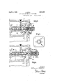
- Figure 1 is a longitudinal section through one e'nd of a valve box provided with a spring pressed valve.
- FIGS 2, 3 and 4 are similar views to Fig- 'mounted on this spindle controls the passage from a cylinder port 6 to the exhaust conduit 65 7.
- Access is had to the valve 5 through an aperture in the wall of the valve box closed by a cover plate 8 carrying a valve guide 9 which is slotted to provide guideways for the Webs of the valve and thus to prevent rotation of the valve about-the longitudinal axis of the spindle.
- the cover plate 8 has a chamber 10 formed therein to enclose a spring held in compression between the end Wall of the chamber and a bearing plate 11 on the spin- 75 dle. In'this arrangement the steam or other fluid owing through the valve can enter the spring chamber 1() and come into direct contact with the spring.
- a spring chamber 12 in the cov- 80 er plate 13 closing the aperture in the Wall of the valve box is open at one end to the passage 14 from which steam or other pressure iuid is admittedto the engine cylinder 15.
- a valve seat 16 is 85 formed and a bearing plate 17 for the spring 18 has a valve surface 19 formed thereon to close on this seat.
- the bearing plate 17 is mounted loosely on the end 2() of the valve spindle to which it transmits the thrust. of 9 the spring-18'the other end of the spring being supported by an adjustable'abutment 22.
- This arrangement is suitable for steam admission valves and provides a means for admitting air to the cylinder when the engme continues to run after steam has been cut off. It is to be noted that in this case the steam is not admitted to the spring chamber.
- the distance of the valve seat 16 from the centre line ofthe cam shaft 1 and the distance of the valve surface 19 from the part of the roller 4 in Contact with the cam 2, are chosen so that, taking into consideration the maximum radius of the cam, the valve 19 will not be closed by the cam and can only be closed by the steam pressure in the steam passage 14 acting against the spring 18.
- the thrust of the spring is transmitted to the valve spindle by a spindle extension or spring plunger 25, vseparate from but abutting against the valve spindle, mounted in a packed guideway 26 in the cover plate 27.
- the sprmg chamber 28 is separate from the cover plate and the spring 29 is held between one end of this chamber and a stirrup 30 mounted on the spindle extension or plunger 25, the compression of the spring being adjustable by means of the studs and nuts 31 holding the spring chamber on the cover plate.
- the spring is entirely cut off from the steam passage.
- valves are varranged in pairs on opposite sides of the cam shaft with their spindles in alignment extending parallel to the cylinder axis with a steam admission valve and an exhaust valve for one end of the cylinder on one side of the cam shaft and corresponding valves for the other end of the cylinder on the other side of this shaft.
- This provides an arrangement which is symmetrical about axes which are respectively parallel and transverse to the cylinder axis.
- the cam shaft 1 and the end of the valve spindles 3 are arranged within a tubular chamber 38 shut olf from the steam and exhaust spaces of the valve box, the spindle extending out through a suitable guide or bearing and having at its outer end a crank or arm 39 by means of which a rotary or oscillatory movement may be imparted to, this shaft.
- cam chamber 38 is arranged between the live steam space 40 and the exhaust space 41 so that each of the spaces can extend from end to end of the valve box. Ihus branching of the steam supply pipe is avoided.
- valve box a valve box, a valve stem, a valve on the valve stem and locatedv in said valve box, a removable cover plate to said valve box, a spring chamber opento the atmosphere and arranged upon the exterior of said cover plate, a spring in said chamber for acting on said valve stem to close the valve, and means for permitting the supplying of air from the spring chamber to the valve box and for preventing the escape of steam from said valve box to the spring chamber.
- valve box In a steam engine, a valve box, a valve stem, a valve on the valve stem, a removable cover plate to said valve box, a spring chamber arranged on the exterior of the cover plate and having its interior in free communication with the atmosphere, a spring in said chamberfor acting on the valve stem to close the valve, and means for allowing air to pass from the spring chamber to the valve 3.
- a valve box, a valve stem, a thrust member separate from and arranged in alignment with the valve stem, a flange on said thrust member, a valve mounted on said valve stem, a removable cover plate to said valve box, a spring chamber open to the atmosphere and arranged upon.
- valve box In a steam engine, a valve box, a valve stem, a thrust member separate from and arranged in alignment with the valve stem, a flange on said thrust member, a valve mounted on said valve stem, webs forming part of said valve', a removable cover plate to said valve box, a spring chamber open to the atmosphere and arranged upon the exterior of said cover plate, a spring in said chamber acting on the flange on said thrust member to move'said valve stem and close the valve, means for allowing air'to pass from the springcohamber to the valve box, and a, valve guideVV mounted in the cover plate and provided with slots in which the Webs of the valve slide.
Landscapes
- Engineering & Computer Science (AREA)
- Mechanical Engineering (AREA)
- General Engineering & Computer Science (AREA)
- Valve-Gear Or Valve Arrangements (AREA)
- Mechanically-Actuated Valves (AREA)
Description
pril.12, 1932. .n.KUPKA VALVE BOX FQR STAM OR LIKE ENGINES Filed Jne l8 1925 3 Sheetsf-Shee l April 12, 1932.
J. KUPKA VALVE BOX FOR STEAM OR LIKE ENGINES l Filed June l8 1925 3 Sheetsj-Sheet 2 Ap'ril 1112, 1932.
J. KUPKA 1,854,044
Box FOR STEAM 0R LIKE ENGINES Filed June 18, 1925 tact with the cams.
Patented Apr. 12, 1932 UNITED STATES JOHANN KUPKA, 0F VIIIIENII'A,l AUSTRIA 'VALVE BOX FOB STEAM 0B LIKE ENGINES Application led June 18, 1925, Serial No. 38,062, and in Great Britain April 29, 19215.v
This invention relates to improvements in l valve gear for steam or like engines, of the this fluid acts on the valves So that the ends of the valve stems, or rollers carried on these stems, are held in contact with the cams by the pressure of the fluid, or by the rush of the Huid if the valve opens slightly. When such valves are applied, for example, to locomotives, in the event of steam being cut off whilst the locomotive continues to travel, for instance, by inertia or along a down grade, the valves may remain lifted and the valve stems or the rollers therein will then be out of con- It is however, in some cases, desirable that the-valve stems or the rollers thereon should at all times be held in contact with the cams and for this purpose it has been 'proposed to provide springs arranged around the valve stems and acting to urge the valves towards their seats. These springs in the constructions heretofore proposed are situated Within the valve box in spaces towhich the fluid under pressure has access so that, in the case of steam engines, the springs are subjected to a high temperature, o r to alternations of high and low temperatures.
According to this invention an improved arrangement of the valve stems is provided wherein the springs are arranged outside the valve box and can therefore be air cooled, the temperature to which they are subjected not rising above the temperature of theA exterior of the valve box. For this purpose the valve stems are extended through the walls of the valve box or through cover plates set therein, and cages or caps are provided to'enclose and protect the spring, these cages or caps also.
, supporting suitable devices serving as abutments for the springs and as'means whereby the'springs can be placed under the required initial stress. p
In the accompanying drawings- Figure 1 is a longitudinal section through one e'nd of a valve box provided with a spring pressed valve. v
Figures 2, 3 and 4 are similar views to Fig- 'mounted on this spindle controls the passage from a cylinder port 6 to the exhaust conduit 65 7. Access is had to the valve 5 through an aperture in the wall of the valve box closed by a cover plate 8 carrying a valve guide 9 which is slotted to provide guideways for the Webs of the valve and thus to prevent rotation of the valve about-the longitudinal axis of the spindle. The cover plate 8 has a chamber 10 formed therein to enclose a spring held in compression between the end Wall of the chamber and a bearing plate 11 on the spin- 75 dle. In'this arrangement the steam or other fluid owing through the valve can enter the spring chamber 1() and come into direct contact with the spring.
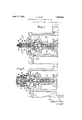
In Figure 2, a spring chamber 12 in the cov- 80 er plate 13 closing the aperture in the Wall of the valve box is open at one end to the passage 14 from which steam or other pressure iuid is admittedto the engine cylinder 15. At this end of the spring chamber a valve seat 16 is 85 formed and a bearing plate 17 for the spring 18 has a valve surface 19 formed thereon to close on this seat. The bearing plate 17 is mounted loosely on the end 2() of the valve spindle to which it transmits the thrust. of 9 the spring-18'the other end of the spring being supported by an adjustable'abutment 22. When steam is admitted to the passage 14, its pressure acts on the dii'erential valve 23 and holds the valve spindle, or its roller, in eontact with the valve operating cam. At the .same time the pressure in this passage closes the valve 19 and compresses the spring 18. When the supply of pressure fluid to the passage 14 is cut o', the spring 18 comes into operation to urge the valve spindle towards the cam and to lift the valve 19 from the valve seat 16 so that air admitted through slots 24 in the wall of the spring chamber can enter the passage 14 and, if the differential valve 23 is opened by the cam, air can pass into the cylinder 15.
This arrangement is suitable for steam admission valves and provides a means for admitting air to the cylinder when the engme continues to run after steam has been cut off. It is to be noted that in this case the steam is not admitted to the spring chamber.
The distance of the valve seat 16 from the centre line ofthe cam shaft 1 and the distance of the valve surface 19 from the part of the roller 4 in Contact with the cam 2, are chosen so that, taking into consideration the maximum radius of the cam, the valve 19 will not be closed by the cam and can only be closed by the steam pressure in the steam passage 14 acting against the spring 18.
In amodified arrangement illustrated in Figure 3, the thrust of the spring is transmitted to the valve spindle by a spindle extension or spring plunger 25, vseparate from but abutting against the valve spindle, mounted in a packed guideway 26 in the cover plate 27. The sprmg chamber 28 is separate from the cover plate and the spring 29 is held between one end of this chamber and a stirrup 30 mounted on the spindle extension or plunger 25, the compression of the spring being adjustable by means of the studs and nuts 31 holding the spring chamber on the cover plate. In this arrangement the spring is entirely cut off from the steam passage.
A similar arrangement is shown in Figure 4. In this case the spring chamber 32 with slots 33 in its walls is formed integrally with the cover plate 34, the stress of the spring 35 being exerted between a stirrup 36 on the spindle extension or plunger and an adjustable cap 37 on the spring'chamber.
The arrangements shown by Figures 3 an 4 do not provide for admission of air to the passage within the cover Aplate and are suitable for either admission or exhaust valves.
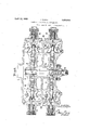
In the arrangements shown in Figure 6 it is to be noted that the valves are varranged in pairs on opposite sides of the cam shaft with their spindles in alignment extending parallel to the cylinder axis with a steam admission valve and an exhaust valve for one end of the cylinder on one side of the cam shaft and corresponding valves for the other end of the cylinder on the other side of this shaft. This provides an arrangement which is symmetrical about axes which are respectively parallel and transverse to the cylinder axis.
Although as shown in Figures 1, 2, 3 and 4 different constructions of the means for supporting the valve springs can be provided, it is preferable that all the spring supporting :the valves also themselves can be of like construction for convenience of manufacture.
The cam shaft 1 and the end of the valve spindles 3 are arranged within a tubular chamber 38 shut olf from the steam and exhaust spaces of the valve box, the spindle extending out through a suitable guide or bearing and having at its outer end a crank or arm 39 by means of which a rotary or oscillatory movement may be imparted to, this shaft. The ends of the chamber 38 and the bearing through which the shaft l'passes can be made steam tight.
It will be noted that the cam chamber 38 is arranged between the live steam space 40 and the exhaust space 41 so that each of the spaces can extend from end to end of the valve box. Ihus branching of the steam supply pipe is avoided.
I claim:
1. In a steam engine, a valve box, a valve stem, a valve on the valve stem and locatedv in said valve box, a removable cover plate to said valve box, a spring chamber opento the atmosphere and arranged upon the exterior of said cover plate, a spring in said chamber for acting on said valve stem to close the valve, and means for permitting the supplying of air from the spring chamber to the valve box and for preventing the escape of steam from said valve box to the spring chamber.
2. In a steam engine, a valve box, a valve stem, a valve on the valve stem, a removable cover plate to said valve box, a spring chamber arranged on the exterior of the cover plate and having its interior in free communication with the atmosphere, a spring in said chamberfor acting on the valve stem to close the valve, and means for allowing air to pass from the spring chamber to the valve 3. In a steam engine, a valve box, a valve stem, a thrust member separate from and arranged in alignment with the valve stem, a flange on said thrust member, a valve mounted on said valve stem, a removable cover plate to said valve box, a spring chamber open to the atmosphere and arranged upon.
the exterior of said cover plate, a spring 1n said chamber acting on the flange on said thrust member to move said valve stem and close the valve, and means for allowing air to pass from the spring chamber yto the valve box.
4. In a steam engine, a valve box, a valve stem, a thrust member separate from and arranged in alignment with the valve stem, a flange on said thrust member, a valve mounted on said valve stem, webs forming part of said valve', a removable cover plate to said valve box, a spring chamber open to the atmosphere and arranged upon the exterior of said cover plate, a spring in said chamber acting on the flange on said thrust member to move'said valve stem and close the valve, means for allowing air'to pass from the springcohamber to the valve box, and a, valve guideVV mounted in the cover plate and provided with slots in which the Webs of the valve slide.
JOHANN KUPKA.
Applications Claiming Priority (1)
| Application Number | Priority Date | Filing Date | Title |
|---|---|---|---|
| GB1854044X | 1925-04-29 |
Publications (1)
| Publication Number | Publication Date |
|---|---|
| US1854044A true US1854044A (en) | 1932-04-12 |
Family
ID=10892028
Family Applications (1)
| Application Number | Title | Priority Date | Filing Date |
|---|---|---|---|
| US3806225 Expired - Lifetime US1854044A (en) | 1925-04-29 | 1925-06-18 | Valve box for steam or like engines |
Country Status (1)
| Country | Link |
|---|---|
| US (1) | US1854044A (en) |
-
1925
- 1925-06-18 US US3806225 patent/US1854044A/en not_active Expired - Lifetime
Similar Documents
| Publication | Publication Date | Title |
|---|---|---|
| US1033204A (en) | Steam-engine valve. | |
| US1854044A (en) | Valve box for steam or like engines | |
| US1239933A (en) | Valve-gear. | |
| US1679794A (en) | Valve gear | |
| US1419693A (en) | Internal-combustion engine | |
| US2136013A (en) | Insert for converting piston-valve engines into poppet-valve engines | |
| US1738435A (en) | Cam-operated balanced valve gear for steam locomotives and like engines | |
| US1303748A (en) | Achille leon francois wattel | |
| US1665966A (en) | Locomotive-valve gear | |
| US912150A (en) | Internal-combustion engine. | |
| US1856523A (en) | Rotary engines | |
| US32589A (en) | Slide-valve fob | |
| US1720206A (en) | Internal-combustion engine | |
| US1349111A (en) | Internal-combustion machine | |
| GB122180A (en) | Improvements in or relating to Control Devices for Inlet and Exhaust Valves of Internal Combustion Engines. | |
| US1529201A (en) | Valve-operating mechanism | |
| US1530047A (en) | Reversing valve | |
| US1668374A (en) | Valve gear for internal-combustion engines | |
| US1689777A (en) | Rotary steam engine | |
| US1964226A (en) | Control of consecutively arranged inlet and exhaust valves in piston steam engines | |
| US1614768A (en) | Oscillating valve for internal-combustion engines | |
| US1145008A (en) | Valve for internal-combustion engines. | |
| US1325904A (en) | Combined inlet and exhaust valve | |
| GB260506A (en) | Improvements in or relating to valve actuating mechanism for internal combustion engines | |
| US1488549A (en) | Internal-combustion engine |