US1854043A - Aeroplane - Google Patents
Aeroplane Download PDFInfo
- Publication number
- US1854043A US1854043A US495203A US49520330A US1854043A US 1854043 A US1854043 A US 1854043A US 495203 A US495203 A US 495203A US 49520330 A US49520330 A US 49520330A US 1854043 A US1854043 A US 1854043A
- Authority
- US
- United States
- Prior art keywords
- air
- wings
- pressure
- aeroplane
- valve
- Prior art date
- Legal status (The legal status is an assumption and is not a legal conclusion. Google has not performed a legal analysis and makes no representation as to the accuracy of the status listed.)
- Expired - Lifetime
Links
- 239000000446 fuel Substances 0.000 description 10
- 239000007789 gas Substances 0.000 description 7
- 238000007599 discharging Methods 0.000 description 5
- 239000012530 fluid Substances 0.000 description 5
- 238000010438 heat treatment Methods 0.000 description 4
- 239000002828 fuel tank Substances 0.000 description 3
- 238000002485 combustion reaction Methods 0.000 description 2
- 230000007812 deficiency Effects 0.000 description 2
- 230000015572 biosynthetic process Effects 0.000 description 1
- 238000010276 construction Methods 0.000 description 1
- 230000007717 exclusion Effects 0.000 description 1
- 238000004880 explosion Methods 0.000 description 1
- 230000002349 favourable effect Effects 0.000 description 1
- 239000000203 mixture Substances 0.000 description 1
- 238000012986 modification Methods 0.000 description 1
- 230000004048 modification Effects 0.000 description 1
Images

Classifications
-
- B—PERFORMING OPERATIONS; TRANSPORTING
- B64—AIRCRAFT; AVIATION; COSMONAUTICS
- B64C—AEROPLANES; HELICOPTERS
- B64C23/00—Influencing air flow over aircraft surfaces, not otherwise provided for
- B64C23/005—Influencing air flow over aircraft surfaces, not otherwise provided for by other means not covered by groups B64C23/02 - B64C23/08, e.g. by electric charges, magnetic panels, piezoelectric elements, static charges or ultrasounds
Definitions
- This invention relates to means for facilitating the control aeroplanes during landing and starting.
- the lift of aeroplanes depends air, upon'the angle of incidence and upon the form'of the wings. Assuming a constant velocity of the plane, the lift increases with the increment of angle of incidence, to a .angle of incidence the values of lift decrease rapidly.
- the cause of it is the initial deficiency of the energy of the air, which streams near the surfaces of the wing and this deficiency occurs at sudden and excessive increments of pressure, and separates the air from the surface of the wing, which leads to a partial inversion of the direction of motion, and to the formation ofwhirls.
- This disadvantage can only be overcome by the artificial supply of energy to the air streaming near the surfaces of the wings.
- the sudden decrease of lift upon passing a maximum angle of incidence happens especially when there is small relative velocitybetween,the aeroplane and the air, and the reduced lift is to be increased by increase of the angle of incidence.
- the machinery must be small and light
- Figure 1 shows an aeroplane or a portion thereof in top plan and horizontal section, and the special apparatus employed fordistributing the heated air to the surface of the wing.
- Figure 2 is a section on line 22 of F igure 1.
- Figure 4 is an enlarged section through structure at the central portion of Figure including a mixing chamber, the air and fuel intake means, a spark plug, and the ducts leading from the mixing chamber toward-the V nozzle of the Wings.
- Figures 5 and 6 are detail views in section, showing two of the nozzles, it being assumed that these elements have been rotated to close their longitudinal discharge slots.
- Prominent features of construction include discharge nozzles in the wings, air storage,
- the tanks are to be filled at the beginning of avflight, and pressure is maintained during the flight without attention on the part of the pilot.
- Motor 13 drives the propeller, and drives through clutch 14 the moving elements of the compressor 15, which discharges through check Valve 17 and pipes 16 to the air-tanks 23.
- Check valve 17 prevents return flow and Valve 19' is closed toward mixing chamber 19 when filling the tanks.
- the air is carried under pressure in storage receptacles 21 in the wings 10, and a valve casing 22 connected with one of these tanks encloses piston 23 having a stem operatively connected with arm 25 of Valve 20, so that rise or fall of the air pressure in tanks 21, which are in communication with each other, will be followed by a corresponding movement of valve 20. At maximum pressure in the tanks 21 valve 20 is partly opened.
- valve 20 increases with the falling pressure in the air-tanks allowing thus to pass that Volume of air, which partly provided with fuel, ignited, and expanded into the mixing chamber, produces there that pressure required for the constant velocity of gases at discharging points.
- a fuel tank is connected by pipe 31 with the mixing chamber or the inlet portion thereof, and a bafile element 23 located as shown in Figure 4 permits a portion of the incoming air and the fuel to pass directly to a chamber 19.
- the fuel pipe will include cut oil? means, and ignition will be effected by means of spark plug 35.
- Pipe 30 supplies air to the fuel tank.
- Exhaust gases from the motor 13 pass through duct 36 under the control of valve 37 and thence to pipe 38 or pipe 38, the latter being a main exhaust duct discharging at the rear.
- Valve 37 is operated by slotted arm 37 and stem 24 of piston 23.
- Pipe 38 is connected with pipes 39 distributing exhaust gases through the air tanks in the planes or wings, but not in contact with the air therein, the air of the tanks being heated and expanded without being mixed with the products of combustion.
- nozzles are mounted in stationary tubular elements or channel members such as member 44 having flanges 45 secured to the wing structure and the; nozzles 46 are rotatable within the devices 44 and are elongated, and each provided with the longitudinal slot 46' and with a flat portion or portions 47, 47 the latter being especially important because the current is discharged directly along the surface of the plane and no obstruction or additional resistance to the movement of the aeroplane through the air is experienced.
- the nozzles are rotatable in the channels 44, and the slots 46 may thereby be closed.
- a nozzle 50 having two longitudinal slots 51 and 52, and having two flat portions adapted to coincide with the upper and lower surface portions of the plane and having the same relation to the surface portions as that indicated in connection with the nozzles 46.
- the stationary channel members for the nozzle 50 are designated 54, 55 and they each have flanges 56 permitting suitable mounting.
- Figure 6 it is assumed that the nozzle has been rotated for the purpose of closing the slots 51 and 52.
- Compressor 15 is placed in operation whenever desired by the use of clutch 14 in order to supply pressure to the nozzles in the wings.
- the apparatus is fully operable with air only, which will be discharged through the nozzles under its own pressure (the Valve of pipe 18 being wide open), but when desired the fuel supply and ignition systems are brought into play, the explosion taking place in channel 18' of Figure 4, which for obvious reasons has a narrow portion at the point shown.
- valve 19' When valve 19' is opened, air passes through pipe 30 to the fuel tank 30, and fuel passes through pipe 31 and its nozzle 31 to channel 18' where decrease in pressure (because of the higher velocity at the nozzle) will press the fuel into portion 18 and produce an inflammable mixture to be ignited by the spark plug 35.
- Air from channel 18" also passes into the mixing chamber 19, and the chamber discharges through pipes 40, 41, 42 to the nozzles of the wings, serving the purpose previously indicated.
- a wing means for distributing fluid under pressure to the surface of the wing and including a duct movable with reference to the longitudinal axis thereinsects 2.
- a structure comprising the elements of claim 1, and channeled means for mounting the nozzle permitting movement of said duct by rotation for closing the 51012..
- a structure comprising the, elements of claim 1, the slotted portion being tangential with reference to the axis of rotation.
- a structure comprising the elements of claim 1, in which the duct has an approximately flat portion adapted to cooperate with the adjacent surface of the wing.
- a structure comprising the elements of claim 1, in which the nozzle includes a second elongated slotted portion discharging tangentially with reference to the longitudinal axis of the duct.
- a structure comprising the elements of claim 6, and automatic controlling means governing the passage of'fiuid toward the Wings.
- heating means for the air thus stored means automatically controlling the heating means and actuated by variation in the pressure of the stored air, and means for directing air to the surface portions of the wings.
- a propeller In an airplane, a propeller, a motor for driving the propeller, an air compressor driven by the motor, a mixing chamber, means for conveying compressed-air and fuel toward the mixing chamber, means for exploding the fuel, and means for conveying the products of combustion and a portion of the air to the surface portions of the wings of the aeroplane.
- a wing means for stor ing air under pressure,mechanical means for controlling the pressure, heating means for controlling the pressure jointly with the mechanical means, and means for discharging the air adjacent to the surface of the wing.
- a wing In an aeroplane, a wing, means for storing air under pressure, means for discharging the air at the surface portion of the wing, and controlling means maintaining a predetermined relation between the initial pressure and the velocity of the air current released at the points of discharge.
Landscapes
- Engineering & Computer Science (AREA)
- Aviation & Aerospace Engineering (AREA)
- Jet Pumps And Other Pumps (AREA)
Description
H. KRNER April 12, 1932.
AEROPLANE Filed Nov. 12, 1930 5 Sheets-Sheet ATTORNEY LI P311 Aprifi 12, 1932.
H. KRNER AEROPLANE I Filed Nov. 12, 1930 3 Sheets-Sheet 2 INVENTOR ATTORNEY Aprifl 12, mm H. mRNER L854,43
AEROPLANE Filed NOV. 12, 1950 3 Sheets-Sheet 3 RTTORNEY Patented Apr. 12, 1932 I UNITED STATES HUBER! xonnnn, or HAB N CUBA AEROPLAN E Application filed November 12, 1930, Serial nb..495,2o3, and in Germany'J'uly 23, .1621.
This invention relates to means for facilitating the control aeroplanes during landing and starting.
The lift of aeroplanes depends air, upon'the angle of incidence and upon the form'of the wings. Assuming a constant velocity of the plane, the lift increases with the increment of angle of incidence, to a .angle of incidence the values of lift decrease rapidly. The cause of it is the initial deficiency of the energy of the air, which streams near the surfaces of the wing and this deficiency occurs at sudden and excessive increments of pressure, and separates the air from the surface of the wing, which leads to a partial inversion of the direction of motion, and to the formation ofwhirls. This disadvantage can only be overcome by the artificial supply of energy to the air streaming near the surfaces of the wings.
- .This was tried by employing revolving cylinders or rotors, whereby the neighboring airmasses are accelerated in the direction of the current; also by opening and closing a slot in the front edge of the wing in the Handley Page machine whereby on account of the difference of pressure between the upper and lower-sides, the air streams from below to above and supplies the required energy. Suction toward the inside of the wing and the tangential discharge of gases were also employed.
The sudden decrease of lift upon passing a maximum angle of incidence, happens especially when there is small relative velocitybetween,the aeroplane and the air, and the reduced lift is to be increased by increase of the angle of incidence. This occurs mainly at starting and landing, for at normal speed the necessary lift is generated by the suffieiently strong pull of the propeller at that most favorable angle-of incidence, which produces also the least drag. Therefore the generation of the artificial lift is limited to the short moments of starting and landing, and occasionally also in sudden vertical currents. According to this invention the artificial lift upon the. relative velocity between aeroplane and the.
is generated by the discharge of burnt gases or air, tangential to the upper and lower sides of the wings. From the preceding it follows that- 1. The machinery must be able to generate the lift suddenly and immediately with full force.
2. This function must be independent of the motor, since it is to be used at landings on account of motor trouble.
3. The machinery must be small and light,
for apparatus is not necessary for the flight ing operations. Since this dead weight has to be carried during the flight, any excess in weight would be undesirable.
4:. The form of the wings, already scientifically developed, must not be changed, nor the drag increased by projecting portions.
With the foregoing and other objects in View, the invention consists in the novel conitself, but only during the landing and startstruction and arrangement of elements herea in disclosed, it being understood that modifications may be made within the scope of the claims, without departing from the spirit of the invention.
In the drawings forming part of this application,
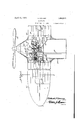
Figure 1 shows an aeroplane or a portion thereof in top plan and horizontal section, and the special apparatus employed fordistributing the heated air to the surface of the wing.
Figure 2 is a section on line 22 of F igure 1. I
on line 33 of Fig Figure 3 is a section ure 1.
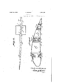
Figure 4 is an enlarged section through structure at the central portion of Figure including a mixing chamber, the air and fuel intake means, a spark plug, and the ducts leading from the mixing chamber toward-the V nozzle of the Wings.
Figures 5 and 6 are detail views in section, showing two of the nozzles, it being assumed that these elements have been rotated to close their longitudinal discharge slots.
Prominent features of construction include discharge nozzles in the wings, air storage,
and fuel supply. The tanks are to be filled at the beginning of avflight, and pressure is maintained during the flight without attention on the part of the pilot.
In Figure 1, the wings or planes are designated 10, a propeller is shown at 11, and a portion of the fuselage is designated 12.
Motor 13 drives the propeller, and drives through clutch 14 the moving elements of the compressor 15, which discharges through check Valve 17 and pipes 16 to the air-tanks 23. Check valve 17 prevents return flow and Valve 19' is closed toward mixing chamber 19 when filling the tanks. The air is carried under pressure in storage receptacles 21 in the wings 10, and a valve casing 22 connected with one of these tanks encloses piston 23 having a stem operatively connected with arm 25 of Valve 20, so that rise or fall of the air pressure in tanks 21, which are in communication with each other, will be followed by a corresponding movement of valve 20. At maximum pressure in the tanks 21 valve 20 is partly opened. During action of the apparatus the opening of valve 20 increases with the falling pressure in the air-tanks allowing thus to pass that Volume of air, which partly provided with fuel, ignited, and expanded into the mixing chamber, produces there that pressure required for the constant velocity of gases at discharging points. i
A fuel tank is connected by pipe 31 with the mixing chamber or the inlet portion thereof, and a bafile element 23 located as shown in Figure 4 permits a portion of the incoming air and the fuel to pass directly to a chamber 19. The fuel pipe will include cut oil? means, and ignition will be effected by means of spark plug 35. Pipe 30 supplies air to the fuel tank.
Exhaust gases from the motor 13 pass through duct 36 under the control of valve 37 and thence to pipe 38 or pipe 38, the latter being a main exhaust duct discharging at the rear.
Valve 37 is operated by slotted arm 37 and stem 24 of piston 23.
Pipe 38 is connected with pipes 39 distributing exhaust gases through the air tanks in the planes or wings, but not in contact with the air therein, the air of the tanks being heated and expanded without being mixed with the products of combustion.
From the mixing chamber 19 the fluid passes through pipes 40, 41, 42 on each side of the chamber to the nozzles shown in Figure 3, and is discharged thence along the surface of the plane or planes.
The nozzles are mounted in stationary tubular elements or channel members such as member 44 having flanges 45 secured to the wing structure and the; nozzles 46 are rotatable within the devices 44 and are elongated, and each provided with the longitudinal slot 46' and with a flat portion or portions 47, 47 the latter being especially important because the current is discharged directly along the surface of the plane and no obstruction or additional resistance to the movement of the aeroplane through the air is experienced. The nozzles are rotatable in the channels 44, and the slots 46 may thereby be closed.
At the right of Figure 3 and in Figure 6, I have illustrated a nozzle 50 having two longitudinal slots 51 and 52, and having two flat portions adapted to coincide with the upper and lower surface portions of the plane and having the same relation to the surface portions as that indicated in connection with the nozzles 46. The stationary channel members for the nozzle 50 are designated 54, 55 and they each have flanges 56 permitting suitable mounting. In Figure 6 it is assumed that the nozzle has been rotated for the purpose of closing the slots 51 and 52.
Assuming that the air tanks 21 have been fill-ed prior to commencing at flight, the air pressure in said tanks will be slightly below maximum and valve 37 will remain open toward pipe 38 until the exhaust gases in pipes 38, 39 have expanded the air sufliciently to operate piston 23 and open Valve 37 to the main exhaust 38 to the exclusion of pipe 38 and pipes 39 connected therewith.
As soon as the air in tanks 21 cools somewhat, piston 23 moving under spring action will throw valve 37 to the left in Figure 1 and the exhaust gases will again impart heat to the air in the tanks.
Compressor 15 is placed in operation whenever desired by the use of clutch 14 in order to supply pressure to the nozzles in the wings.
' The apparatus is fully operable with air only, which will be discharged through the nozzles under its own pressure (the Valve of pipe 18 being wide open), but when desired the fuel supply and ignition systems are brought into play, the explosion taking place in channel 18' of Figure 4, which for obvious reasons has a narrow portion at the point shown.
When valve 19' is opened, air passes through pipe 30 to the fuel tank 30, and fuel passes through pipe 31 and its nozzle 31 to channel 18' where decrease in pressure (because of the higher velocity at the nozzle) will press the fuel into portion 18 and produce an inflammable mixture to be ignited by the spark plug 35.
Air from channel 18" also passes into the mixing chamber 19, and the chamber discharges through pipes 40, 41, 42 to the nozzles of the wings, serving the purpose previously indicated.
What I claim is-.
1. In an aeroplane, a wing, means for distributing fluid under pressure to the surface of the wing and including a duct movable with reference to the longitudinal axis thereinsects 2. A structure comprising the elements of claim 1, and channeled means for mounting the nozzle permitting movement of said duct by rotation for closing the 51012..
3. A structure comprising the, elements of claim 1, the slotted portion being tangential with reference to the axis of rotation.
4. A structure comprising the elements of claim 1, in which the duct has an approximately flat portion adapted to cooperate with the adjacent surface of the wing.
5. A structure comprising the elements of claim 1, in which the nozzle includes a second elongated slotted portion discharging tangentially with reference to the longitudinal axis of the duct.
6. In an airplane, means responsive to pressure variation in the wings for heating fluid for discharge through the structure of the wings, means for compressing the fluid, and 1 means for directing said fluid along the surfaces of the wings.
7. A structure comprising the elements of claim 6, and automatic controlling means governing the passage of'fiuid toward the Wings.
8. In an airplane, means for storing air,
heating means for the air thus stored, means automatically controlling the heating means and actuated by variation in the pressure of the stored air, and means for directing air to the surface portions of the wings.
9. In an airplane, a propeller, a motor for driving the propeller, an air compressor driven by the motor, a mixing chamber, means for conveying compressed-air and fuel toward the mixing chamber, means for exploding the fuel, and means for conveying the products of combustion and a portion of the air to the surface portions of the wings of the aeroplane.
10. In an aeroplane, a wing, means for stor ing air under pressure,mechanical means for controlling the pressure, heating means for controlling the pressure jointly with the mechanical means, and means for discharging the air adjacent to the surface of the wing.
11. In an aeroplane, a wing, means for storing air under pressure, means for discharging the air at the surface portion of the wing, and controlling means maintaining a predetermined relation between the initial pressure and the velocity of the air current released at the points of discharge.
In testimony whereof I aifix my signature.
nnnnn'r KoRNnn.
Applications Claiming Priority (1)
| Application Number | Priority Date | Filing Date | Title |
|---|---|---|---|
| DE1854043X | 1927-07-23 |
Publications (1)
| Publication Number | Publication Date |
|---|---|
| US1854043A true US1854043A (en) | 1932-04-12 |
Family
ID=7746130
Family Applications (1)
| Application Number | Title | Priority Date | Filing Date |
|---|---|---|---|
| US495203A Expired - Lifetime US1854043A (en) | 1927-07-23 | 1930-11-12 | Aeroplane |
Country Status (1)
| Country | Link |
|---|---|
| US (1) | US1854043A (en) |
Cited By (15)
| Publication number | Priority date | Publication date | Assignee | Title |
|---|---|---|---|---|
| US2430431A (en) * | 1943-03-12 | 1947-11-04 | Lanier Aircraft Corp | Airplane wing lift modification |
| US2437732A (en) * | 1943-01-12 | 1948-03-16 | Ferrel Ind Inc | Apparatus for propelling and increasing the lift of airplanes |
| US2449022A (en) * | 1945-03-12 | 1948-09-07 | Edward A Stalker | Fuel system for aircraft power plants for aircraft propulsion and boundary layer aircontrol |
| US2450709A (en) * | 1943-02-22 | 1948-10-05 | Lockheed Aircraft Corp | Aircraft control |
| US2468787A (en) * | 1943-09-09 | 1949-05-03 | Catherine D Sharpe | Aerodynamic impelling device |
| US2503172A (en) * | 1942-08-17 | 1950-04-04 | Cierva Autogiro Co Ltd | Helicopter with jet reaction for counteracting torque |
| US2568813A (en) * | 1945-09-28 | 1951-09-25 | Svenska Turbinfab Ab | Jet-propelled aircraft with boundary layer control |
| US2604277A (en) * | 1945-03-31 | 1952-07-22 | Rateau Soc | Jet propulsion and boundary layer control system for aircraft |
| US2609168A (en) * | 1947-09-10 | 1952-09-02 | James A Mcnally | Jet airfoil brake |
| US2873931A (en) * | 1953-08-24 | 1959-02-17 | Fleischmann Carlo | Boundary layer control apparatus for improving the action of aircraft |
| US2896881A (en) * | 1955-04-29 | 1959-07-28 | John S Attinello | Aerodynamic air brake and lift spoiler for aircraft |
| US3124322A (en) * | 1964-03-10 | Aircraft with fluid sustaining means | ||
| US3275266A (en) * | 1959-10-20 | 1966-09-27 | Hovercraft Dev Ltd | Foils for movement in a fluid |
| US20060102800A1 (en) * | 2002-07-24 | 2006-05-18 | Saddoughi Seyed G | Method and apparatus for modulating flow separation |
| US20090145129A1 (en) * | 2006-09-11 | 2009-06-11 | The Scuderi Group, Llc | Split-cycle aircraft engine |
-
1930
- 1930-11-12 US US495203A patent/US1854043A/en not_active Expired - Lifetime
Cited By (16)
| Publication number | Priority date | Publication date | Assignee | Title |
|---|---|---|---|---|
| US3124322A (en) * | 1964-03-10 | Aircraft with fluid sustaining means | ||
| US2503172A (en) * | 1942-08-17 | 1950-04-04 | Cierva Autogiro Co Ltd | Helicopter with jet reaction for counteracting torque |
| US2437732A (en) * | 1943-01-12 | 1948-03-16 | Ferrel Ind Inc | Apparatus for propelling and increasing the lift of airplanes |
| US2450709A (en) * | 1943-02-22 | 1948-10-05 | Lockheed Aircraft Corp | Aircraft control |
| US2430431A (en) * | 1943-03-12 | 1947-11-04 | Lanier Aircraft Corp | Airplane wing lift modification |
| US2468787A (en) * | 1943-09-09 | 1949-05-03 | Catherine D Sharpe | Aerodynamic impelling device |
| US2449022A (en) * | 1945-03-12 | 1948-09-07 | Edward A Stalker | Fuel system for aircraft power plants for aircraft propulsion and boundary layer aircontrol |
| US2604277A (en) * | 1945-03-31 | 1952-07-22 | Rateau Soc | Jet propulsion and boundary layer control system for aircraft |
| US2568813A (en) * | 1945-09-28 | 1951-09-25 | Svenska Turbinfab Ab | Jet-propelled aircraft with boundary layer control |
| US2609168A (en) * | 1947-09-10 | 1952-09-02 | James A Mcnally | Jet airfoil brake |
| US2873931A (en) * | 1953-08-24 | 1959-02-17 | Fleischmann Carlo | Boundary layer control apparatus for improving the action of aircraft |
| US2896881A (en) * | 1955-04-29 | 1959-07-28 | John S Attinello | Aerodynamic air brake and lift spoiler for aircraft |
| US3275266A (en) * | 1959-10-20 | 1966-09-27 | Hovercraft Dev Ltd | Foils for movement in a fluid |
| US20060102800A1 (en) * | 2002-07-24 | 2006-05-18 | Saddoughi Seyed G | Method and apparatus for modulating flow separation |
| US7198234B2 (en) * | 2002-07-24 | 2007-04-03 | General Electric Company | Method and apparatus for modulating flow separation |
| US20090145129A1 (en) * | 2006-09-11 | 2009-06-11 | The Scuderi Group, Llc | Split-cycle aircraft engine |
Similar Documents
| Publication | Publication Date | Title |
|---|---|---|
| US1854043A (en) | Aeroplane | |
| US2396911A (en) | Reaction propelling device for aircraft | |
| US2498939A (en) | Gas turbine tail burner fuel control | |
| US2648192A (en) | Variable capacity jet exhaust augmenter | |
| US2420323A (en) | Wing-mounted jet-propulsion system with controllable discharge outlet | |
| US2886946A (en) | Thrust reversing device for turbojet engines | |
| US2912188A (en) | Jet propelled aircraft with tiltable combustion chambers | |
| US2514513A (en) | Jet power plant with boundary layer control for aircraft | |
| US2402363A (en) | Turbine apparatus | |
| US2671620A (en) | Control means for aircraft and aircraft power plant installations | |
| US2786331A (en) | Fuel feed and power control for gas turbine engines | |
| US2410538A (en) | Prime mover | |
| US2616254A (en) | Jet engine fuel control for modifying fuel pressure drop across throttle in accordance with altitude | |
| US3532100A (en) | Silencing of gas turbine engines | |
| US2912189A (en) | Jet propelled aircraft with jet flaps | |
| US3380660A (en) | Variable area exhaust deflector | |
| US3454227A (en) | Free floating articulate ejector nozzle | |
| US2488174A (en) | Air flow inducing system for aircooled internal-combustion engines | |
| US3291420A (en) | Wing structure and duct means for aircraft | |
| US2864236A (en) | Method of and means for the control of the air inlet opening of a jet propulsion unit or a gas turbine engine | |
| USRE23198E (en) | Reaction propelling device for | |
| US3149804A (en) | Anti-stall system | |
| US2566961A (en) | Pressure control for thrust nozzles for turbines | |
| US2564107A (en) | Fuel feeding control for gas turbines responsive to fuel flow, temperature, and acceleration | |
| US2880579A (en) | Automatic buzz control |