US1854029A - Chuck for embossing and vending apparatus - Google Patents
Chuck for embossing and vending apparatus Download PDFInfo
- Publication number
- US1854029A US1854029A US479064A US47906430A US1854029A US 1854029 A US1854029 A US 1854029A US 479064 A US479064 A US 479064A US 47906430 A US47906430 A US 47906430A US 1854029 A US1854029 A US 1854029A
- Authority
- US
- United States
- Prior art keywords
- chuck
- jaws
- blank
- anvil
- embossing
- Prior art date
- Legal status (The legal status is an assumption and is not a legal conclusion. Google has not performed a legal analysis and makes no representation as to the accuracy of the status listed.)
- Expired - Lifetime
Links
- 238000004049 embossing Methods 0.000 title description 8
- 230000000295 complement effect Effects 0.000 description 6
- 230000006835 compression Effects 0.000 description 3
- 238000007906 compression Methods 0.000 description 3
- 238000010276 construction Methods 0.000 description 1
- 230000002093 peripheral effect Effects 0.000 description 1
Images
Classifications
-
- B—PERFORMING OPERATIONS; TRANSPORTING
- B44—DECORATIVE ARTS
- B44B—MACHINES, APPARATUS OR TOOLS FOR ARTISTIC WORK, e.g. FOR SCULPTURING, GUILLOCHING, CARVING, BRANDING, INLAYING
- B44B5/00—Machines or apparatus for embossing decorations or marks, e.g. embossing coins
- B44B5/02—Dies; Accessories
- B44B5/026—Dies
-
- Y—GENERAL TAGGING OF NEW TECHNOLOGICAL DEVELOPMENTS; GENERAL TAGGING OF CROSS-SECTIONAL TECHNOLOGIES SPANNING OVER SEVERAL SECTIONS OF THE IPC; TECHNICAL SUBJECTS COVERED BY FORMER USPC CROSS-REFERENCE ART COLLECTIONS [XRACs] AND DIGESTS
- Y10—TECHNICAL SUBJECTS COVERED BY FORMER USPC
- Y10T—TECHNICAL SUBJECTS COVERED BY FORMER US CLASSIFICATION
- Y10T279/00—Chucks or sockets
- Y10T279/18—Pivoted jaw
Definitions
- My invention relates to an improvedapparatus f for embossing aV blank and vending thesame, and relates more particularlyto an' .improved chuck for supporting and grip- 5 ping the Vblank during the embossing vof charactersthereon and which is adapted to release the blank upon completionoiv the' embossing operation and to receive and" ygrip successive blanks.
- YOne of the ⁇ objects of my invention is to Y maintainy relatively ksubstantial axial align ment ofthe chuck bodyy and the blank sup- I porting anvil and to provide a blank-support which vwill accurately position' thelinished l blank inthe plane of a succeeding unembossedblank, so that the' finished blank may be properly ,discharged and the unembossed blank'properly positioned on theanvilto be gripped by the chuck jaws.
- :Another object of my. invention is to construct a chuck of'thistype in -which anY -in- Y creased Contact area is provided betweenj the chuck body and the anvil.
- Another object of my invention is tofpro- '-vide, aehuck of this type which is simple of constructiom; extremely durable, j andV which may readily be disassembled if desired.
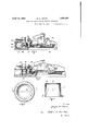
- Figure 1 is a longitudinallsection, partly v in elevation, omy improved chuck showing the saine applied in use and in position wherein. the aws ,are closed. to grip ablank- Sup- 4@ported inthe chuck.
- p y is a longitudinallsection, partly v in elevation, omy improved chuck showing the saine applied in use and in position wherein. the aws ,are closed. to grip ablank- Sup- 4@ported inthe chuck.
- Figure 2 is. a viewsimilar tovL Figure 1 f except that the chuck. actuating slide has ⁇ been moved tothe right vupon completion of the g embossing operation.l In thisview the clutch z vis-open; and theanvil projected upwardly to discharge the :finished blankV from the chuck.
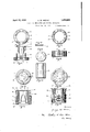
- Figure' isa bottom view of the chuck shell or-ease.
- p I i f Figure ⁇ @ is a section taken on kline 5050fF-igure A3.
- Figure 5 is a topplan View oiasection of the chuck base.
- Vmentary base section shown in- Figure 7.
- Figure 9 is a side elevation of onefo't the 60 ,jaw supporting pins gripped between the uppery and lower'ba-se sectionsfwhenthesarne are assembled one Vupon the other.
- l-- Figure 10- is an elevat-ionwoi'V af blank supporting anvil which operates axially ofthe 65 g- Figure 11-is abottom plan view oftheV anvil.
- Figure 13 is al section taken on line 13-13 ot Figure 12 showing thezshell4 in-broken Figure 14 is .a top. .plan :view-ot the V'chuck 75 and anvil .showing the l,chuck jawsin open ,position .fand the, anvil raised for lreleasing and lifting the nished blank intorthe path of the next succeeding unembossed blank
- Figure v15 is a side-elevation of lthe. chuck so shown in Figurell. l
- iMy invention relates .particularly to an improved chuek: for; use. in an embossing-and vending apparatus lsuch as is4 disclosed .in my Y United States Patent No. 1,494,839 patented 85 May V'20, 1924, wherein the blank isirmly gripped during the embossingoperation yand is, when subsequently released, raised i above the planeaofthe jaws sothat the iinished lblank may be ⁇ discharged .and-a: newablank 90 substituted in itsplacebygthe operation .of a
- Each of the jaws is pivotally carried by a pin 3 passing through an opening in a lower part of the This is illustrated clearly in Figure 6.
- the arcuate jaws of the chuck each comprise a body portion 6 the side walls of which converge downwardly toward the lower offset portion while the upper ends of the jaws terminate in blank gripping aw faces 7 having an outwardly extending flange 8.
- the flange 8 is provided with an outwardly inclined wall 9 which is adapted to engage a similarly inclined wall 10 of the chuck shell or casing 11 in a manner which will be described more fully hereinafter.
- the inner or gripping face of the fiange is serrated as at 12 to permit the jaws to more iirmly grip a blank inserted therebetween.
- a complementary base section 13, forming a part of the chuck body, is likewise cut away radially at corresponding points as at 14- for purposes which will be described more fully hereinafter.
- the base section 13 is also provided on its lower peripheral face with aligned grooves 15 which cooperate with the respective aligned grooves 2 formed in the base 1.
- This means includes substantially aligned pins 17 and 18 carried by the base 13 and the lower ⁇ olfset portions of the jaws 5 respectively. It will be noted that the lower portions of the jaws extend outwardlyfrom the planes of the jaws to provide a suflicient support for the pins 18.
- Compression coil springs 19 are carried by the pins 17 and 18 to exert a normal.downward-pressure on the offset lower portion of the jaws and in a plane out of the axis of the pins 3 to normally force the'jaws toward the position sho-wn in Figure 15.
- the chuck is movable axially in a shell or casing 11 illustrated in detail in Figures 3 and 4, and shown in broken lines in Figure 13, the shell having an annular inwardly extending flange 20 one of the walls of which is inclined as at 10 for engagement with the inclined walls 9 of the respective jaws 6. It will be not-ed that by virtue of the superimposed complementary base sections 1 and 13- an enlarged circumferential contact area is provided for the chuck for sliding engagement with the internal walls of the shell 11. Because of this increased contact or bearing area between ⁇ the walls of the shell and the chuck relative axial movement of these parts is assured and relative side motion is prevented.
- the anvil 21 is adapted to move relatively axially of the chuck to support and raise the blank out of the plane of the gripping faces of the jaws when the jaws are in open position.
- the increased area of contact between the parts accurately positions the blank -so that it may be discharged when released from the chuckV and a succeeding blank substituted in the former blanks position.
- Figure 1 the blank 22 is shown gripped between the jaws of the chuck where it is securely held during the embossing operation.
- a magazine 23 which supplies the uneinbossed blanks one at a time to the slide 24 which operates therebeneath by suitable mechanism.
- the slide passes under the mouth of the magazine and is rounded inl wardly at one end to receive a blank from the magazine and propel it to the supporting anvil.
- the slide is supported in a frame member 25 and is connected through a post or spacing member 26 to the slide 27.
- 'Ihe slide 27 extends and moves beneath the chuck and shell assembly and is provided with a rack 28 near one end for driving connection with a propelling gear sector 29.
- That portion of the slide 27 which moves beneath the chuck and shell assembly is provided with independent cam faces 30 and 31, the former extending along the marginal longitudinal walls of the slide for engagement with the bottom face of the base section 1 of the chuck, while the latter cam face 31 engages the bottom face of the anvil 21.
- These cams are staggered longitudinally so that in moving the slide 27 from left to right as in Figure 2, the chuck body engaging the cam faces 30 is moved axially upwardly to release the jaws 6 from the blank 22, prior to an axial upward movement of the anvil 21 as a result of the bottom anvil face riding up the cam 31.
- a chuck having an axial bore for movably receiving, an article support, the body of said chuck having a plurality of openings there? ly dispose the jaws in open article receiving position.
- a compression spring 40 is carried within the shell 11 and exerts and axial pressure to maintain the chuck body in pressure engagement with the cams 30 or'the upper faces 4:1
- a chuck having an axial bore for movably receiving an, article support, said chuck including a base portion having openings therein, jaws pivotally carried by the base and having radially offset .portions operating in said openings, compression springs engaging said offset portions of the jaws and a Wall of said openings, said chuck base portion comprising separable complementary sections, each section having cooperating grooves on their adjacent faces, vand jaw supporting pins carried in the respective cooperating grooves and gripped thereby when the said
Landscapes
- Shaping Metal By Deep-Drawing, Or The Like (AREA)
Description
April l2, 1932. G. w. HEENE CHUCK FOR EMBOSSNG AND VENDING APPARATUS FledvAug. 30. 1930 2 Sheets-Sheet l zi B1 April 12, 1932. G Wh HEENE 1,854,029
CHUCK FOR EMBOSSI'NG AND VENDING APPARATUS Filed Aug. 30, 1930 2 Sheets-Sheet 2 Patented Apr. 12, 1932 nerf-ENT @FF f HG'EORGE iWJHEENE, OFRCL'EVELAND, OHIO CHUCKl FOB EMBOSSING AND `rVEIVDZIBTG APPARATUS Appiication 'med August 3o,
My invention relates to an improvedapparatus f for embossing aV blank and vending thesame, and relates more particularlyto an' .improved chuck for supporting and grip- 5 ping the Vblank during the embossing vof charactersthereon and which is adapted to release the blank upon completionoiv the' embossing operation and to receive and" ygrip successive blanks. v
" YOne of the `objects of my invention is to Y maintainy relatively ksubstantial axial align ment ofthe chuck bodyy and the blank sup- I porting anvil and to provide a blank-support which vwill accurately position' thelinished l blank inthe plane of a succeeding unembossedblank, so that the' finished blank may be properly ,discharged and the unembossed blank'properly positioned on theanvilto be gripped by the chuck jaws.
:Another object of my. invention is to construct a chuck of'thistype in -which anY -in- Y creased Contact area is provided betweenj the chuck body and the anvil. y Another object of my invention is tofpro- '-vide, aehuck of this type which is simple of constructiom; extremely durable, j andV which may readily be disassembled if desired.
:Other object-s and advantagesofmy inventionzwill become more lapparent as thefollowing v'description of. an embodiment thereof progresses reference being Vmadeytoathe accompanying'drawings in which -like reference characters are` employed to designate v like parts throughoutthe same.
Figure 1 is a longitudinallsection, partly v in elevation, omy improved chuck showing the saine applied in use and in position wherein. the aws ,are closed. to grip ablank- Sup- 4@ported inthe chuck. p y
Figure 2 is. a viewsimilar tovLFigure 1 f except that the chuck. actuating slide has `been moved tothe right vupon completion of the g embossing operation.l In thisview the clutch z vis-open; and theanvil projected upwardly to discharge the :finished blankV from the chuck. s Figure'isa bottom view of the chuck shell or-ease. p I i fFigure `@is a section taken on kline 5050fF-igure A3.
' lines.
1930. serial No.4 479,064.-
Figure 5 is a topplan View oiasection of the chuck base.
Vmentary base section shown in-Figure 7.
Figure 9 is a side elevation of onefo't the 60 ,jaw supporting pins gripped between the uppery and lower'ba-se sectionsfwhenthesarne are assembled one Vupon the other.
l--Figure 10-is an elevat-ionwoi'V af blank supporting anvil which operates axially ofthe 65 g-Figure 11-is abottom plan view oftheV anvil. Y Y Y, j
Figure: 12 is a top. plan view `of the:=assem -bled chuck andanvil showing thechuck jaws 70 in closedposition.
Figure 13: is al section taken on line 13-13 otFigure 12 showing thezshell4 in-broken Figure 14 is .a top. .plan :view-ot the V'chuck 75 and anvil .showing the l,chuck jawsin open ,position .fand the, anvil raised for lreleasing and lifting the nished blank intorthe path of the next succeeding unembossed blank Figure v15 is a side-elevation of lthe. chuck so shown in Figurell. l
iMy invention relates .particularly to an improved chuek: for; use. in an embossing-and vending apparatus lsuch as is4 disclosed .in my Y United States Patent No. 1,494,839 patented 85 May V'20, 1924, wherein the blank isirmly gripped during the embossingoperation yand is, when subsequently released, raised i above the planeaofthe jaws sothat the iinished lblank may be` discharged .and-a: newablank 90 substituted in itsplacebygthe operation .of a
`singlelever ,and Aassociated mechanism by' the operator.
Referring more particularlyrtoFigures. 5 to 15; inclusive, inwhich `I have; illustrated 95 an embodiment` of my winvention, 1I have shown a; preferred-v form `oi myuinvention-in which the parts Vmay be-readilyiassembled 'or disassembled. 1^ provide. a base 1 forming part of the chuck .bodyian'dhavinga lpluralr- '100 CII ity of aligned grooves 2 formed in its upper face for receiving the jaw supporting pins 3 of the type illustrated in detail in Figure 9. Portions of the upper face of the base are cut away radially as at l for receiving the lower oset ends of the respective clutch jaws. Each of the jaws is pivotally carried by a pin 3 passing through an opening in a lower part of the This is illustrated clearly in Figure 6. The arcuate jaws of the chuck each comprise a body portion 6 the side walls of which converge downwardly toward the lower offset portion while the upper ends of the jaws terminate in blank gripping aw faces 7 having an outwardly extending flange 8. The flange 8 is provided with an outwardly inclined wall 9 which is adapted to engage a similarly inclined wall 10 of the chuck shell or casing 11 in a manner which will be described more fully hereinafter. The inner or gripping face of the fiange is serrated as at 12 to permit the jaws to more iirmly grip a blank inserted therebetween.
A complementary base section 13, forming a part of the chuck body, is likewise cut away radially at corresponding points as at 14- for purposes which will be described more fully hereinafter.
The base section 13 is also provided on its lower peripheral face with aligned grooves 15 which cooperate with the respective aligned grooves 2 formed in the base 1. When the complementary base sections are assembled and secured together by means of the bolts 16 as shown in Figure 13 the respective pins 3 which pivotally support the respective jaws 6 are clamped in place between the grooves 2 and 15.
Although I have shown my chuck as having four jaws for engaging and gripping the blank it is obvious that a greater or less number of aws may be used without departing from the spirit of my invention or the scope of the appended claims.
I have provided means carried by the chuck for normally disposing the aws out of a vertical plane so that an object held by the jaws when in closed position may be released by relatively moving the chuck body and shell 11. This means includes substantially aligned pins 17 and 18 carried by the base 13 and the lower` olfset portions of the jaws 5 respectively. It will be noted that the lower portions of the jaws extend outwardlyfrom the planes of the jaws to provide a suflicient support for the pins 18. Compression coil springs 19 are carried by the pins 17 and 18 to exert a normal.downward-pressure on the offset lower portion of the jaws and in a plane out of the axis of the pins 3 to normally force the'jaws toward the position sho-wn in Figure 15. complementary base sections are aligned as shown in Figure 15 when the parts are as- The radial openings d and 14: of thel sembled and are adapted to partially inclose the lower enlarged portion of the jaw and the springs 19. In this manner none of the parts extend beyond the outer periphery of the base sections 1 and 13.
The chuck is movable axially in a shell or casing 11 illustrated in detail in Figures 3 and 4, and shown in broken lines in Figure 13, the shell having an annular inwardly extending flange 20 one of the walls of which is inclined as at 10 for engagement with the inclined walls 9 of the respective jaws 6. It will be not-ed that by virtue of the superimposed complementary base sections 1 and 13- an enlarged circumferential contact area is provided for the chuck for sliding engagement with the internal walls of the shell 11. Because of this increased contact or bearing area between `the walls of the shell and the chuck relative axial movement of these parts is assured and relative side motion is prevented. It will also be noted that because of the increased contact or bearing area of the internal walls of bore of the complementary sections 1 and 13 relative axial movement between the anvil 21 and the internal walls of the chuck is also assured without the danger of relative side movement between these parts.V The anvil 21 is adapted to move relatively axially of the chuck to support and raise the blank out of the plane of the gripping faces of the jaws when the jaws are in open position. The increased area of contact between the parts accurately positions the blank -so that it may be discharged when released from the chuckV and a succeeding blank substituted in the former blanks position. Y
Referring now more particularly to Figures l and 2 of the drawings in which I have illustrated an embodiment of my invention in use in an embossing and vending apparatus similar to that disclosed in my United States Fatent No. 1,49%,839 patented May 20, 1924, I have shown the relative positions of the chuck jaws and other parts under conditionsof use. j
In Figure 1 the blank 22 is shown gripped between the jaws of the chuck where it is securely held during the embossing operation.
I have shown a magazine 23 which supplies the uneinbossed blanks one at a time to the slide 24 which operates therebeneath by suitable mechanism. The slide passes under the mouth of the magazine and is rounded inl wardly at one end to receive a blank from the magazine and propel it to the supporting anvil. The slide is supported in a frame member 25 and is connected through a post or spacing member 26 to the slide 27. 'Ihe slide 27 extends and moves beneath the chuck and shell assembly and is provided with a rack 28 near one end for driving connection with a propelling gear sector 29. That portion of the slide 27 which moves beneath the chuck and shell assembly is provided with independent cam faces 30 and 31, the former extending along the marginal longitudinal walls of the slide for engagement with the bottom face of the base section 1 of the chuck, while the latter cam face 31 engages the bottom face of the anvil 21. These cams are staggered longitudinally so that in moving the slide 27 from left to right as in Figure 2, the chuck body engaging the cam faces 30 is moved axially upwardly to release the jaws 6 from the blank 22, prior to an axial upward movement of the anvil 21 as a result of the bottom anvil face riding up the cam 31. As the anvil is lifted it raises the released blank to a plane above the jaw faces of the chuckwvhere it is discharged into a delivery chute by a new blank from the magazine. A -spring 32 assists in returning the slides 24 and 27 to the position in Figure 1.
It will be noted that when the chuck body base section are assembled together, to pivotally support said jaws on the base.
2. In an apparatus of the class described, a chuck having an axial bore for movably receiving, an article support, the body of said chuck having a plurality of openings there? ly dispose the jaws in open article receiving position. 1
In testimony whereof, I hereunto afiix my signature.
GEORGE W. HEENE.
is lifted in the shell by the cams 30, the com- Y pression of the springs 19 is released to open the jaws 6 as in Figure 15. As the chuck is raised in the shell the cooperating inclined surfaces 9 and 10 of the jaws and shell respectively slide one over the other.
A compression spring 40 is carried within the shell 11 and exerts and axial pressure to maintain the chuck body in pressure engagement with the cams 30 or'the upper faces 4:1
of the slide 27 depending upon the position of the slide.
As the slide 27 is returned to the left as in Figure 1 the anvil or ejector 21 moves downwardly in advance of the chuck body, to lower the new blank into the plane of the jaw faces 12. Then the chuck is lowered in the shell and the inclined faces 9 of the jaws slide over the annular inclined faces 10 of the shell grip the same.
In Figure 2, I have illustrated at 42 an em- A- bossed blank being discharged from the chuck and a new blank on the anvil.
Variousch'anges may be made in the details of construction and arrangement of parts without departing from the spirit of the invention or the scope of the appended claims.
I claim:
1. In an apparatus of the class described, a chuck having an axial bore for movably receiving an, article support, said chuck including a base portion having openings therein, jaws pivotally carried by the base and having radially offset .portions operating in said openings, compression springs engaging said offset portions of the jaws and a Wall of said openings, said chuck base portion comprising separable complementary sections, each section having cooperating grooves on their adjacent faces, vand jaw supporting pins carried in the respective cooperating grooves and gripped thereby when the said
Priority Applications (1)
| Application Number | Priority Date | Filing Date | Title |
|---|---|---|---|
| US479064A US1854029A (en) | 1930-08-30 | 1930-08-30 | Chuck for embossing and vending apparatus |
Applications Claiming Priority (1)
| Application Number | Priority Date | Filing Date | Title |
|---|---|---|---|
| US479064A US1854029A (en) | 1930-08-30 | 1930-08-30 | Chuck for embossing and vending apparatus |
Publications (1)
| Publication Number | Publication Date |
|---|---|
| US1854029A true US1854029A (en) | 1932-04-12 |
Family
ID=23902515
Family Applications (1)
| Application Number | Title | Priority Date | Filing Date |
|---|---|---|---|
| US479064A Expired - Lifetime US1854029A (en) | 1930-08-30 | 1930-08-30 | Chuck for embossing and vending apparatus |
Country Status (1)
| Country | Link |
|---|---|
| US (1) | US1854029A (en) |
-
1930
- 1930-08-30 US US479064A patent/US1854029A/en not_active Expired - Lifetime
Similar Documents
| Publication | Publication Date | Title |
|---|---|---|
| US2027922A (en) | Method of making wrench sockets | |
| GB2040198A (en) | Closed die forging operation | |
| US2158312A (en) | Machine for making a barrel | |
| US2515841A (en) | Tube closing apparatus | |
| DE2830150C2 (en) | Device for producing moldings from thermoplastic material | |
| US1854029A (en) | Chuck for embossing and vending apparatus | |
| US4055977A (en) | Method and apparatus for making double groove pulleys | |
| US1950726A (en) | Die press | |
| CN104439007A (en) | Die capable of ejecting materials at multiple stations | |
| JPS63165025A (en) | Punching die | |
| US2343006A (en) | Machine for making closure caps | |
| US1335908A (en) | Die | |
| US2642916A (en) | Forming die | |
| US2433808A (en) | Forming device | |
| US1977164A (en) | Means for making articles having a polygonal cross section | |
| US1355351A (en) | Combined metal-barrel corrugating and edging machine | |
| US1348650A (en) | Can-closing machine | |
| US1249399A (en) | Can-heading machine. | |
| US2398373A (en) | Metalworking machine | |
| US810023A (en) | Collapsible die for wiring or beading. | |
| US1384049A (en) | Machine for securing end closures in vessels | |
| US2380462A (en) | Can body necking-in machine | |
| US1183523A (en) | Sheet-metal-shaping means. | |
| US1957924A (en) | Apparatus for forming metal articles | |
| US519062A (en) | Executors of andreas syversen |