US1853987A - Automobile radiator cap ornament - Google Patents
Automobile radiator cap ornament Download PDFInfo
- Publication number
- US1853987A US1853987A US578348A US57834831A US1853987A US 1853987 A US1853987 A US 1853987A US 578348 A US578348 A US 578348A US 57834831 A US57834831 A US 57834831A US 1853987 A US1853987 A US 1853987A
- Authority
- US
- United States
- Prior art keywords
- ornament
- automobile radiator
- radiator cap
- cap
- automobile
- Prior art date
- Legal status (The legal status is an assumption and is not a legal conclusion. Google has not performed a legal analysis and makes no representation as to the accuracy of the status listed.)
- Expired - Lifetime
Links
- 241000282472 Canis lupus familiaris Species 0.000 description 2
- 238000010276 construction Methods 0.000 description 2
- 101100440696 Caenorhabditis elegans cor-1 gene Proteins 0.000 description 1
- 240000005860 Portulaca grandiflora Species 0.000 description 1
- 210000005069 ears Anatomy 0.000 description 1
- 238000004519 manufacturing process Methods 0.000 description 1
Images
Classifications
-
- A—HUMAN NECESSITIES
- A63—SPORTS; GAMES; AMUSEMENTS
- A63H—TOYS, e.g. TOPS, DOLLS, HOOPS OR BUILDING BLOCKS
- A63H33/00—Other toys
- A63H33/40—Windmills; Other toys actuated by air currents
Definitions
- the invention relates to an automobile radiator cap ornament and more especially to a motion ornament for mounting upon the radiator caps of automobiles or other motor driven vehicles.
- the primary object of the invention is the provision of an ornament of this character, wherein movable objects, such for example as those imitative of racing horses, dogs or,
- Another object of the invention is the provision of an ornament of this character which is extremely simple in construction, readily and easily mounted upon anddemounted from the cap of an automobile radiator and in position thereon will automatically operate, being'possessed of few parts yet the same is strong, durable, and
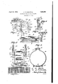
- Figure 1 is a side elevationof the ornament constructed in accordance with the invention mounted upon an automobile radiator cap showing by full lines one position of the ob jects and by. dotted lines other positions 7 f, thereof during the working of the same.
- Figure 2 is a front elevation.
- Figure 3 is a sectional view on the line 3+3 of Figure 2.
- r Figure 4 is a fragmentary vertical detail sectional view.
- Y r 1 Figure 5 is a'perspective view of one of the 7 rocker members of'the ornament. I 7
- faclamping ring'10 which is in the form of a split internally channeled band having outturned terminalears 11', the channel of the band being adapted to accommodate the'periphery of said cap B while engaged through 0 the ears 11 is a nut carrying bolt 13 so that [the said band can be made fast about the cap to embrace the same.
- i v a Carried at the forward portion of the ring is a U-shaped frame 13 the flattened intermediate portion 140i which is riveted as at 15 or-otherwise secured to the ring 10 with the arms or uprights 16 vertically disposed in spaced parallel relation to each other. J ournaled'. transversely in the arms or up-"70 rights 16-is ashaft 17 which carries a wind blade 18, the same being fixed to the shaft between the armsor uprights 1610f the frame wind impact for, the
- rockers 19 Arranged upon the frame 13 outside of the same are rockers 19, these through the medium of offset extensions 20 are supported upon pivots 21 while the slotted levers '22 of 7 said rockers have engaged therein terminal '80 cranks 23, these being reversely set for reverse operation of said rockers 19 on the rotation of the blade 18 under wind impact.
- each rocker 19 has a cross barj25 which-is disposed in ternally of the object 24 and is coupled there tothrough the medium of rivets 26 which are through the body of. said through the cross bar 25 of the rocker 19 so that the object 24 will be made fast and carried directly by the rocker.
- the crossbars 25 onthe rockers '19 are disposed parallel with each other and longitudinally directed with respect to the longitudinal extent of an automobile so that the 1 heads of the objects 2 101:; the rockers will be.
- cranks 23 it Will be apparent that the objects Will have a reverse disposition and this will cause the motion thereof when operated on rotation of the Wind blade 18, the latter being driven by Wind pressure, the blade be ing reversely curved for the driving of the objects inonedirection.
- V An ornament of the character described comprising a pair of hollow bodies indicative of running images, substantially 'T-shaped members :each .presenting a cross :bar fastenedinteriorhy of each'zbodyand having a slotted stem projected exteriorly of and beneath said body,':an ear extended laterally from thestemabove the slots therein, an auto- :mobile radiator caplengaging bracket and .constitnting spaced bearings, pivots projected from the :bearingsand swiingingly supportingsaid 263133 of the stem, 'aadouble crank shaft journaled in said ?bearings and engaging the slots in the stems, and a Wind 0perated blade fired to the shaft between the bearings for rotating saidshaft.
Landscapes
- Vehicle Interior And Exterior Ornaments, Soundproofing, And Insulation (AREA)
Description
April 12, 1932.. 1.. R. Moss ET AL 1,853,987
AUTOMOBILE RADIATOR CAP ORNAMENT Filed Dec. 1, 1931 WITNESS: ,y I ATTORNEY With these and other objects in view, the
Patented Apr. 12, 1932 V UNITED STATES LEE R. MOSS AND CHARLES 1). counts, or sAiiij EGQ, GALIVEFORNIA, -,1 r
AUTOMOBILE imnm'ron oer onivAiyr Nr Application filed' Deeember 1, 1931 "Serial No. 578,348.
The invention relates to an automobile radiator cap ornament and more especially to a motion ornament for mounting upon the radiator caps of automobiles or other motor driven vehicles.
The primary object of the invention is the provision of an ornament of this character, wherein movable objects, such for example as those imitative of racing horses, dogs or,
3) the like, will be set in motion under Wind pressure so as to be attractive and ornamentally effective, the mounting of the ornament being novel in fo rmand likewise the to. a 7
Another object of the invention is the provision of an ornament of this character which is extremely simple in construction, readily and easily mounted upon anddemounted from the cap of an automobile radiator and in position thereon will automatically operate, being'possessed of few parts yet the same is strong, durable, and
' Band is operated by inexpensive to manufacture.
invention consists in the features of construction, combination and arrangement of parts as will be hereinafter more fully described in detail, illustrated in the accompanying drawings, which discloses the preferred embodiment of the invention, and pointed out in the claim hereunto appended.
In the accompanying drawings Figure 1 is a side elevationof the ornament constructed in accordance with the invention mounted upon an automobile radiator cap showing by full lines one position of the ob jects and by. dotted lines other positions 7 f, thereof during the working of the same.
Figure 2 is a front elevation. Figure 3 is a sectional view on the line 3+3 of Figure 2. r Figure 4 is a fragmentary vertical detail sectional view. Y r 1 Figure 5 is a'perspective view of one of the 7 rocker members of'the ornament. I 7
Similar reference characters indicate cor-1 responding parts throughout the several views in the drawings. I. i r Referring to the 'drawingszin detail, A
working thereof for imparting motion thereobject 24 and also designates generally the filling spout of an automobile 'radiator'. and B the closure cap' *for said spoutwhich'cap is demountable from V the spout and is of a standard type. Engageable peripherally with the cap :B'is
faclamping ring'10 which is in the form of a split internally channeled band having outturned terminalears 11', the channel of the band being adapted to accommodate the'periphery of said cap B while engaged through 0 the ears 11 is a nut carrying bolt 13 so that [the said band can be made fast about the cap to embrace the same. i v a Carried at the forward portion of the ring is a U-shaped frame 13 the flattened intermediate portion 140i which is riveted as at 15 or-otherwise secured to the ring 10 with the arms or uprights 16 vertically disposed in spaced parallel relation to each other. J ournaled'. transversely in the arms or up-"70 rights 16-is ashaft 17 which carries a wind blade 18, the same being fixed to the shaft between the armsor uprights 1610f the frame wind impact for, the
rotation of the shaft 17 V V 7 Arranged upon the frame 13 outside of the same are rockers 19, these through the medium of offset extensions 20 are supported upon pivots 21 while the slotted levers '22 of 7 said rockers have engaged therein terminal '80 cranks 23, these being reversely set for reverse operation of said rockers 19 on the rotation of the blade 18 under wind impact.
The rockers support objects 24, in this instance, being imitative of racing horses al-c8 though they may be imitative ofothe r ani-'' mals such as dogs or the likecand each rocker 19 has a cross barj25 which-is disposed in ternally of the object 24 and is coupled there tothrough the medium of rivets 26 which are through the body of. said through the cross bar 25 of the rocker 19 so that the object 24 will be made fast and carried directly by the rocker. The crossbars 25 onthe rockers '19 are disposed parallel with each other and longitudinally directed with respect to the longitudinal extent of an automobile so that the 1 heads of the objects 2 101:; the rockers will be.
passed transversely free.; 13; the reverse disposition of the tunes.
It is eof (course 'toibe understood that while the objects 24 are shown of a certain imitative character these may be varied for imitation of other-objects-of animate kind lVhat is claimed is V An ornament of the character described comprising a pair of hollow bodies indicative of running images, substantially 'T-shaped members :each .presenting a cross :bar fastenedinteriorhy of each'zbodyand having a slotted stem projected exteriorly of and beneath said body,':an ear extended laterally from thestemabove the slots therein, an auto- :mobile radiator caplengaging bracket and .constitnting spaced bearings, pivots projected from the :bearingsand swiingingly supportingsaid 263133 of the stem, 'aadouble crank shaft journaled in said ?bearings and engaging the slots in the stems, and a Wind 0perated blade fired to the shaft between the bearings for rotating saidshaft.
In testimony whereof we zaffix our signa- LE-ESRMOSS. CHABLES D. COLLINS.
Priority Applications (1)
| Application Number | Priority Date | Filing Date | Title |
|---|---|---|---|
| US578348A US1853987A (en) | 1931-12-01 | 1931-12-01 | Automobile radiator cap ornament |
Applications Claiming Priority (1)
| Application Number | Priority Date | Filing Date | Title |
|---|---|---|---|
| US578348A US1853987A (en) | 1931-12-01 | 1931-12-01 | Automobile radiator cap ornament |
Publications (1)
| Publication Number | Publication Date |
|---|---|
| US1853987A true US1853987A (en) | 1932-04-12 |
Family
ID=24312479
Family Applications (1)
| Application Number | Title | Priority Date | Filing Date |
|---|---|---|---|
| US578348A Expired - Lifetime US1853987A (en) | 1931-12-01 | 1931-12-01 | Automobile radiator cap ornament |
Country Status (1)
| Country | Link |
|---|---|
| US (1) | US1853987A (en) |
-
1931
- 1931-12-01 US US578348A patent/US1853987A/en not_active Expired - Lifetime
Similar Documents
| Publication | Publication Date | Title |
|---|---|---|
| US2648087A (en) | Windshield wiper | |
| DE102016002986A1 (en) | Belt tension adjustment device for engine | |
| DE102004049672B4 (en) | two-wheeled vehicle | |
| US4896915A (en) | Wind deflector plate for snow plow | |
| US1807501A (en) | Flash light holder | |
| US1853987A (en) | Automobile radiator cap ornament | |
| US2188612A (en) | Automobile visor map roller attachment | |
| US2686571A (en) | Movably supported engine and drive assembly and wheel drive control therefor | |
| US1706447A (en) | Radiator protector | |
| US655316A (en) | Mud-guard for bicycles. | |
| US1728079A (en) | Whirligig device for automobiles | |
| US2230165A (en) | Fan attachment for land vehicles | |
| US2326267A (en) | Windshield attachment | |
| US1952863A (en) | Rear view mirror | |
| US1504679A (en) | Extensible bumper for vehicles | |
| US1380910A (en) | Mirror for automobiles | |
| US1354826A (en) | Traction attachment | |
| US2570970A (en) | Spring support for bicycle seats | |
| US1741513A (en) | Bumper for motor vehicles | |
| US744483A (en) | Automatic pump. | |
| US1881222A (en) | Tire carrier | |
| US2048926A (en) | Vehicle | |
| US3145047A (en) | Deflector for motor vehicles | |
| US2248313A (en) | Vehicle drive | |
| US1718162A (en) | Vehicle signal |