US1853966A - Talking machine and record therefor - Google Patents
Talking machine and record therefor Download PDFInfo
- Publication number
- US1853966A US1853966A US390966A US39096629A US1853966A US 1853966 A US1853966 A US 1853966A US 390966 A US390966 A US 390966A US 39096629 A US39096629 A US 39096629A US 1853966 A US1853966 A US 1853966A
- Authority
- US
- United States
- Prior art keywords
- tape
- record
- spool
- sound
- tension
- Prior art date
- Legal status (The legal status is an assumption and is not a legal conclusion. Google has not performed a legal analysis and makes no representation as to the accuracy of the status listed.)
- Expired - Lifetime
Links
- 238000000034 method Methods 0.000 description 5
- 238000010276 construction Methods 0.000 description 2
- 229920002160 Celluloid Polymers 0.000 description 1
- 238000004026 adhesive bonding Methods 0.000 description 1
- 230000015572 biosynthetic process Effects 0.000 description 1
- 238000007796 conventional method Methods 0.000 description 1
- 230000001419 dependent effect Effects 0.000 description 1
- 239000012634 fragment Substances 0.000 description 1
- 238000004519 manufacturing process Methods 0.000 description 1
- 239000000463 material Substances 0.000 description 1
- 230000001105 regulatory effect Effects 0.000 description 1
Images
Classifications
-
- G—PHYSICS
- G11—INFORMATION STORAGE
- G11B—INFORMATION STORAGE BASED ON RELATIVE MOVEMENT BETWEEN RECORD CARRIER AND TRANSDUCER
- G11B15/00—Driving, starting or stopping record carriers of filamentary or web form; Driving both such record carriers and heads; Guiding such record carriers or containers therefor; Control thereof; Control of operating function
- G11B15/18—Driving; Starting; Stopping; Arrangements for control or regulation thereof
- G11B15/26—Driving record carriers by members acting directly or indirectly thereon
- G11B15/34—Driving record carriers by members acting directly or indirectly thereon through non-slip drive means, e.g. sprocket
Definitions
- the object of my device is to make a talking machine such as the modern graphophone, in which a record tape will be used instead of the conventional record.
- My device employs the conventional sound box and tone arm and needle and may be either spring or motor operated. It ismade 80 of few and simple parts, that lend themselves readily to multiple production and may be easily and cheaply made and easily and cheaply replaced.
- a further obj ect is to so construct the record tape that both sides maybe used for the sound depression and that all points of both sides will be presented to the needle without any changing or turning of the tape.
- a still further object is to motivate the tape, so as to preserve the proper tension on the tape over the area in which the tape comes in contact with the needle.
- a still further object is to put a twist or turn in the tape and have the twist orturn atthe dependent suspendedend and to provide means for easily and simply loosening the ends of the tape7 because in operation the tape is endless.
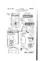
- Fig. 1 is a plan view of the top of a talking machine with the tonal arm sound box and needle illustrated, as well as the operatively and externally visible portion of the record tape.
- Fig. 2 is a vertical sectional elevation on line 2 2 of Fig. 1.
- Fig. 3 is a schematic view of the record tape showing the driving spool and tension spool together with the rollers that hold the externally visible portion of the record tape 1n operative position.
- Fig. 4 is a section of the record tape showing the spirally shaped sound depressions and the lateral slots for engagement with the driving and tension spools.
- Fig. 5 is a front elevation of said spool together with the shaft and a conventional motor attached to the shaft.
- y Fig. 6 shows an end elevation of the driving spool.
- Fig. 7 is a perspective view of the record tape showing the turn in the tape.
- F1g.'8 is a fragment of the tape ends showing their jointure.
- Fig. 9 is a storing spool for the tape with the tape shown in position.
- Fig. 9a is a modied form of a construction that will permit the use of a tape at greatly increased length.
- Fig. 9b is a schematic View of the driving and tension spools together with the record tape 16 when the latter is of the non-continuous type, showing a simple method of attachin@ the tape ends to the core of each spool ⁇
- Fig. 9c is a cross section taken 0n the line SBC-9c of Fig. 8.
- Numeral 10 designates the talking machine cabinet having the top plate 11, the oscillating tone arm 12 and the rectangular tape opening 130.
- Numeral 14 designates the sound box and l5 the'needle. The parts thus far described with the exception of the tape opening 13 are conventional.
- Numeral 16 designates the record tape, which is rectangular in'shape and has the lateral slots 17 formed therein.
- Numeral 18 designates the sound depression, which may be either 'of the vertical or lateral type and when the ends of the record tape are joined together, as will be subsequently described, the sound depressions 18 will be formed spirally, i. e., they will proceed from one side around the entire tape and on both sides of it to the other side of the tape.
- the driving spool 20 within the cabinet 10 on the shaft 19 is positioned the driving spool 20.
- This driving spool 2() is best illustrated in Figures 5 and 6 and is formed of the core 21 and the serrated disks 22, which ar-e symmetrically secured at the ends of he core 21.
- the motor 23 which may be either a spring motor or an electric motor, the driving shaft of which is connected directly to the shaft 19. It will be seen, therefore, that when the motor 23 is operated that the driving spool 20 will be rotated.
- Numeral 24 designates a tension spool, which is rotatively mounted on the shaft 25, which shaft is mounted in the machine cabinet 10, as indicated in Fig. 2.
- the tension spool 24 is of the same shape and size as the driving spool 20 and has serrated disks having .teeth of the same pitch as the teeth on the serrated disks 23.
- Numeral 26 designates a roller rotatively positioned in the machine cabinet 10 immediately adjacent one end of thev tape opening 13 and extending across the opening and being slightly greater in width, than the width of the record tape 16.
- Numeral 27 designates a roller similarly positioned in the machine cabinet 10, but at the opposite end, of the tape opening 13.
- the record tape 16 is positioned over the rollers 26 and 27 and over the tension spool 24 and the driving spool 20, so that the teeth of the serrated disks of the tension spool 24 and of the driving spool 20 are in mesh with the lateral slots 17 of the record tape 16.
- the ends of the record tape 16 are not joined directly, but a simple turn' is made in the tape before the jointure is effected. This turn is particularly shown in Fig. 7.
- the ends o'f the record tape 16 are then joined as are the ends of -a power belt, but preferably so that there is a positive continuity between the surfaces of the belt ends.
- a This may be accomplished by having eyes 28 secured to one end and perforated projections 29 secured to the other end.
- Numeral 30 designates a pin, which passes through the eyes 28 and the perforated projections 29, thereby securing the jointure between the record tape ends Without making the jointure rigid and permitting the clficient passing of the tape, -over the driving spool 2O and the tension spool 24.
- a plate 31 may be secured to the machine cabinet 10 leaving slots for the ingress and egress of the record tape in and out of slots in the top plate 11.
- the oscillating tone arm 12 will then e oscilla-ted in the conventional manner by the Since there is practically no limit to thel length that the record tape may have inthe talking machine cabinet, and since both sides are utilized, it is easily seen that there is no particular limit 'to the linear extent of the sound depressions 18.
- the record tape may be made of Celluloid, rubber, or any like material, which is thick enough and stable enough to receive the sound depressions 18 and which still will permit the slight bend-l travel of the needle 15 insound depressionsY ner, as in the case of the conventional photographic films, which are secured to a s ool and the tape Wrapped around the spoo as lshown in Fig. 9b.
- the operation may be repeated for as many linear sound depressions as appear on one side of the tape.
- the driving spool may then be removed so that the reverse side ofthe spool will be presented to the needle 15. It will bef-observed that the same amount of music may be played from the non-continuous tape as from the continuous tape, but in the former it becomes necessary to reverse the spools at the end of every linear sound depression, while in the latter all the sound depressions may be played that appear on both .sides without anyinterruption and Without any manualoperation.
- a phonograph cabinet spools rotativelyV mounted therein, plates mounted therein, a
- a phonograph cabinet spools rotatively mounted therein, plates mounted therein, a" continuous record tape having a twist therein passing over said spools and over and around and between said plates for increasing the length of said continuous record tape.
- tape has been used here, but it is not intended thereby expressly or implicity to limit its width.
- a wide tape or sheet may be used.
- the length of the spiral sound devpression varies directly with the width of the tape andwith its length.
- the sound depression may be linear and' need not be spiral in form.
- the continuous tape need not interfere with the horn in the conventional'talking machine cabinet for it may be suspended on the sides of the horn and the twist may be suspended below the horn.
- the tape maybe made to pass over and under baille plates, as is shown in Fig. 9a inwhich the record tape 16 is made to pass under and over the baffle plates 36 which plates may be secured in the cabinet 10 in any conyventional manner.
- lateral slots 17 and serrated disks such as 22 for positive driving of the record tape 16.
- Any other conventional method may be used as spools without serrated disks or tapes having elevations laterally positioned for engagementwith depressions in the spools 20 and 24:.
Landscapes
- Storage Of Web-Like Or Filamentary Materials (AREA)
Description
April 12, 1932. A. c. EcKER''r v TALKING MACHINE AND Rggonn THEREFR Original Filed Nov. 2, 1928 Patented Apr.- 12, 1932 PATENT OFFICE ARTHUR C. ECKERT, F ST. LOUIS, MISSOURI TALKING- MACHINE AND4 RECORD THEREFOR Original application led November 2, 1928, Serial No. 316,763. Divided and this application -led September 7, 1929.
The object of my device is to make a talking machine such as the modern graphophone, in which a record tape will be used instead of the conventional record. This is 'a divi- J sional application, divided out of applicants patent application for talking machines and records therefor, filed November 2, 1928, serial No. 316,7 63.
In the use of the conventional record it bem comes necessary after one side of the record is played to reverse the record in order to play the other side. There is likewise a definite particular limitation in the diameter of records. For this reason it Iis not practical 151 in the conventionalV machine to play continuously for a great length of time without breaking the continuity and without the effort of reversing and changing records. In
addition, the storing of numerous records is quite a problem on account of their necessary l size and weight, etc. With the device herein described, it will be possible to play for many hours without any interruption whatsoever, and without any manual eifort. It will be possible to play a complete opera continuously without any manipulation.
My device employs the conventional sound box and tone arm and needle and may be either spring or motor operated. It ismade 80 of few and simple parts, that lend themselves readily to multiple production and may be easily and cheaply made and easily and cheaply replaced.
A further obj ect is to so construct the record tape that both sides maybe used for the sound depression and that all points of both sides will be presented to the needle without any changing or turning of the tape.
A still further object is to motivate the tape, so as to preserve the proper tension on the tape over the area in which the tape comes in contact with the needle.
A still further object is to put a twist or turn in the tape and have the twist orturn atthe dependent suspendedend and to provide means for easily and simply loosening the ends of the tape7 because in operation the tape is endless.
50 A still further object is to pro'vide means Serial No. 390,966.
for the facile storing ofthe tape with the greatest possible space efficiency.
With these and other objectsin view my invention has relation to certain novel features of construction and arrangement of parts, as will be hereinafter more fully described, pointed out in the claims, and illustrated in the drawings in which Fig. 1 is a plan view of the top of a talking machine with the tonal arm sound box and needle illustrated, as well as the operatively and externally visible portion of the record tape.
Fig. 2 is a vertical sectional elevation on line 2 2 of Fig. 1.
Fig. 3 is a schematic view of the record tape showing the driving spool and tension spool together with the rollers that hold the externally visible portion of the record tape 1n operative position.
Fig. 4 is a section of the record tape showing the spirally shaped sound depressions and the lateral slots for engagement with the driving and tension spools.
Fig. 5 is a front elevation of said spool together with the shaft and a conventional motor attached to the shaft. y Fig. 6 shows an end elevation of the driving spool.
Fig. 7 is a perspective view of the record tape showing the turn in the tape.
F1g.'8 is a fragment of the tape ends showing their jointure.
Fig. 9 is a storing spool for the tape with the tape shown in position. Fig. 9a is a modied form of a construction that will permit the use of a tape at greatly increased length.
Fig. 9b is a schematic View of the driving and tension spools together with the record tape 16 when the latter is of the non-continuous type, showing a simple method of attachin@ the tape ends to the core of each spool` Fig. 9c is a cross section taken 0n the line SBC-9c of Fig. 8.
Numeral 10 designates the talking machine cabinet having the top plate 11, the oscillating tone arm 12 and the rectangular tape opening 130.
Numeral 14 designates the sound box and l5 the'needle. The parts thus far described with the exception of the tape opening 13 are conventional.
Numeral 16 designates the record tape, which is rectangular in'shape and has the lateral slots 17 formed therein. Numeral 18 designates the sound depression, which may be either 'of the vertical or lateral type and when the ends of the record tape are joined together, as will be subsequently described, the sound depressions 18 will be formed spirally, i. e., they will proceed from one side around the entire tape and on both sides of it to the other side of the tape. within the cabinet 10 on the shaft 19 is positioned the driving spool 20. This driving spool 2() is best illustrated in Figures 5 and 6 and is formed of the core 21 and the serrated disks 22, which ar-e symmetrically secured at the ends of he core 21. Mounted withinthe machine cabinet 10 is the motor 23, which may be either a spring motor or an electric motor, the driving shaft of which is connected directly to the shaft 19. It will be seen, therefore, that when the motor 23 is operated that the driving spool 20 will be rotated. Numeral 24 designates a tension spool, which is rotatively mounted on the shaft 25, which shaft is mounted in the machine cabinet 10, as indicated in Fig. 2. The tension spool 24 is of the same shape and size as the driving spool 20 and has serrated disks having .teeth of the same pitch as the teeth on the serrated disks 23. Numeral 26 designates a roller rotatively positioned in the machine cabinet 10 immediately adjacent one end of thev tape opening 13 and extending across the opening and being slightly greater in width, than the width of the record tape 16. Numeral 27 designates a roller similarly positioned in the machine cabinet 10, but at the opposite end, of the tape opening 13. The record tape 16 is positioned over the rollers 26 and 27 and over the tension spool 24 and the driving spool 20, so that the teeth of the serrated disks of the tension spool 24 and of the driving spool 20 are in mesh with the lateral slots 17 of the record tape 16. The ends of the record tape 16 are not joined directly, but a simple turn' is made in the tape before the jointure is effected. This turn is particularly shown in Fig. 7. The ends o'f the record tape 16 are then joined as are the ends of -a power belt, but preferably so that there is a positive continuity between the surfaces of the belt ends. A This may be accomplished by having eyes 28 secured to one end and perforated projections 29 secured to the other end. Numeral 30 designates a pin, which passes through the eyes 28 and the perforated projections 29, thereby securing the jointure between the record tape ends Without making the jointure rigid and permitting the clficient passing of the tape, -over the driving spool 2O and the tension spool 24.
In the event that it is desired to have the Mounted tension spool 24 and driving spool 20 as Well as the rollers 26 and 27 removable, it is not necessary to have a selective juncture between the belt ends. by gluing or other methods, which will not disturb the continuity of the sound depressions 18 to any extent. It willbe seen that when the motor 23 is operated that the driving spool 2O will-pull the record tape 16 by virtue of the contact of the teeth of the serrated disks 22 in the slots 17 over and around the rollers 27 and 26 and will rotate the tension spool 24 by ivirtue of a similar contact. By a proper positioning of the record tape 16 on the tension spool 24, the tension of the record tape between the rollers 26 and 27 may be` regulated. If it is desired to have a positive support for the record tape While it is passing The juncture may then be made over the tape opening 13, a plate 31 may be secured to the machine cabinet 10 leaving slots for the ingress and egress of the record tape in and out of slots in the top plate 11. It
will be noted that owing to the turn in the record tape 16, which turn will always remain below the tension spool 24 and the driving4 spool 20 that every ,point on both sides of the record tape 16v will pass over the tape opening 13. When this tape is rotating, and the sound box, oscillating arm and needle are placed in their operative position with the needle in one ofthe sound depressions 18, all of the sound depressions on both sides of the re-cord tape will comein contact with the needle 15, since the sound depressions are continuous and are of spiral formation and on account of the turn in the record tape 16. The oscillating tone arm 12, will then e oscilla-ted in the conventional manner by the Since there is practically no limit to thel length that the record tape may have inthe talking machine cabinet, and since both sides are utilized, it is easily seen that there is no particular limit 'to the linear extent of the sound depressions 18. The record tape may be made of Celluloid, rubber, or any like material, which is thick enough and stable enough to receive the sound depressions 18 and which still will permit the slight bend-l travel of the needle 15 insound depressionsY ner, as in the case of the conventional photographic films, which are secured to a s ool and the tape Wrapped around the spoo as lshown in Fig. 9b. The free end willthen be passed'over the rollers 26 and 27 as was the case in the continuing tape heretofore described, and then secured to the core of the driving spool 20. When the motor 23 is actuated, the tape will be drawn under the needle -movable from the Shafts 19 and 25 or the shafts must be secured to their respective spools, in which instance they will be re- .moved with the spool. In this form-oitl my device, only 011e linear sound depression need bc made on the tape. VVh'en the tape has beenl wound on the driving spool 20, the spool 2O may be replaced with the spool 24 and the process repeated on a second sound depression that may be made on the same side of the same tape. In this manner the operation may be repeated for as many linear sound depressions as appear on one side of the tape. The driving spool may then be removed so that the reverse side ofthe spool will be presented to the needle 15. It will bef-observed that the same amount of music may be played from the non-continuous tape as from the continuous tape, but in the former it becomes necessary to reverse the spools at the end of every linear sound depression, while in the latter all the sound depressions may be played that appear on both .sides without anyinterruption and Without any manualoperation.
around the core for several turns. This Secures a positive selective attachment between the tape ends and the spools.
What I claim and mean tosecure by Letters Patent is:
1. A phonograph cabinet, spools rotativelyV mounted therein, plates mounted therein, a
continuous record tape passing over said spools and over and around and between said plates for increasing the length of said continuous record tape.
2. A phonograph cabinet, spools rotatively mounted therein, plates mounted therein, a" continuous record tape having a twist therein passing over said spools and over and around and between said plates for increasing the length of said continuous record tape.
In testimony whereof I aliix my signature.
ARTHUR C. vECKERT.
The term tape has been used here, but it is not intended thereby expressly or implicity to limit its width. A wide tape or sheet may be used. The length of the spiral sound devpression varies directly with the width of the tape andwith its length.
In the instance of a non-continuous tape, the sound depression may be linear and' need not be spiral in form. The continuous tape need not interfere with the horn in the conventional'talking machine cabinet for it may be suspended on the sides of the horn and the twist may be suspended below the horn.
For lengthening the tape that is used, it is not intended to be limited to the method disclosed with the idler rollers 32 and 33. Another method that may be used is the' following: The tape maybe made to pass over and under baille plates, as is shown in Fig. 9a inwhich the record tape 16 is made to pass under and over the baffle plates 36 which plates may be secured in the cabinet 10 in any conyventional manner.
It is not intended 'to limit the disclosure herein to the use of lateral slots 17 and serrated disks such as 22 for positive driving of the record tape 16. Any other conventional method may be used as spools without serrated disks or tapes having elevations laterally positioned for engagementwith depressions in the spools 20 and 24:.
Priority Applications (1)
| Application Number | Priority Date | Filing Date | Title |
|---|---|---|---|
| US390966A US1853966A (en) | 1928-11-02 | 1929-09-07 | Talking machine and record therefor |
Applications Claiming Priority (2)
| Application Number | Priority Date | Filing Date | Title |
|---|---|---|---|
| US316763A US1853895A (en) | 1928-11-02 | 1928-11-02 | Talking machine and record therefor |
| US390966A US1853966A (en) | 1928-11-02 | 1929-09-07 | Talking machine and record therefor |
Publications (1)
| Publication Number | Publication Date |
|---|---|
| US1853966A true US1853966A (en) | 1932-04-12 |
Family
ID=26980583
Family Applications (1)
| Application Number | Title | Priority Date | Filing Date |
|---|---|---|---|
| US390966A Expired - Lifetime US1853966A (en) | 1928-11-02 | 1929-09-07 | Talking machine and record therefor |
Country Status (1)
| Country | Link |
|---|---|
| US (1) | US1853966A (en) |
Cited By (5)
| Publication number | Priority date | Publication date | Assignee | Title |
|---|---|---|---|---|
| DE743413C (en) * | 1935-07-25 | 1943-12-27 | Jean Jonesco | Additional device for record speaking machines |
| US2460411A (en) * | 1944-03-09 | 1949-02-01 | Raymond T Moloney | Sound recorder |
| US2899507A (en) * | 1959-08-11 | Loading means for magnetic | ||
| US2962200A (en) * | 1953-10-15 | 1960-11-29 | Int Standard Electric Corp | Guiding means for a magnetic tape |
| FR2576443A1 (en) * | 1985-01-21 | 1986-07-25 | Obeniche Paul | DEVICE FOR RECORDING A SOUND MESSAGE ON THE INNER SURFACE OF A RING, CORRESPONDING READING DEVICE AND RING THUS RECORDED |
-
1929
- 1929-09-07 US US390966A patent/US1853966A/en not_active Expired - Lifetime
Cited By (6)
| Publication number | Priority date | Publication date | Assignee | Title |
|---|---|---|---|---|
| US2899507A (en) * | 1959-08-11 | Loading means for magnetic | ||
| DE743413C (en) * | 1935-07-25 | 1943-12-27 | Jean Jonesco | Additional device for record speaking machines |
| US2460411A (en) * | 1944-03-09 | 1949-02-01 | Raymond T Moloney | Sound recorder |
| US2962200A (en) * | 1953-10-15 | 1960-11-29 | Int Standard Electric Corp | Guiding means for a magnetic tape |
| FR2576443A1 (en) * | 1985-01-21 | 1986-07-25 | Obeniche Paul | DEVICE FOR RECORDING A SOUND MESSAGE ON THE INNER SURFACE OF A RING, CORRESPONDING READING DEVICE AND RING THUS RECORDED |
| EP0191670A1 (en) * | 1985-01-21 | 1986-08-20 | Paul Obeniche | Sound message-recording device on the inner surface of a ring, playback device therefor and ring thus recorded |
Similar Documents
| Publication | Publication Date | Title |
|---|---|---|
| US1853966A (en) | Talking machine and record therefor | |
| US2551198A (en) | Record mechanism | |
| US2288983A (en) | Telegraphone device | |
| US2944750A (en) | Tape recorder indicator attachment | |
| US1853895A (en) | Talking machine and record therefor | |
| US2335053A (en) | Method and device for making hair ribbon bows | |
| US2372810A (en) | Constant speed drive for magnetic recorders | |
| US2070431A (en) | Chart board | |
| US3265318A (en) | Magnetic tape machine | |
| US2638699A (en) | Fishing leader kit | |
| US3743758A (en) | Optical metronome | |
| US2526051A (en) | Telegraphone | |
| US2084782A (en) | Animated motion picture machine | |
| US2525230A (en) | Wire rope making machine | |
| US2480742A (en) | Magazine type magnetic recording apparatus | |
| US3225640A (en) | Musical toy | |
| US3405584A (en) | Apparatus for electrically actuating a musical instrument | |
| US3300107A (en) | Apparatus for making ornamental articles | |
| US1326864A (en) | Selective controlling apparatus for electric circuits | |
| US1089835A (en) | Phonograph-record. | |
| US2487976A (en) | Movable supporting base for sound record tape | |
| US2225323A (en) | Sound reproducing apparatus | |
| US1166925A (en) | Apparatus for recording and reproducing sound. | |
| US3267791A (en) | Reed construction | |
| US2184728A (en) | Metronome |