US1853895A - Talking machine and record therefor - Google Patents
Talking machine and record therefor Download PDFInfo
- Publication number
- US1853895A US1853895A US316763A US31676328A US1853895A US 1853895 A US1853895 A US 1853895A US 316763 A US316763 A US 316763A US 31676328 A US31676328 A US 31676328A US 1853895 A US1853895 A US 1853895A
- Authority
- US
- United States
- Prior art keywords
- tape
- spool
- record
- sound
- tension
- Prior art date
- Legal status (The legal status is an assumption and is not a legal conclusion. Google has not performed a legal analysis and makes no representation as to the accuracy of the status listed.)
- Expired - Lifetime
Links
- 238000000034 method Methods 0.000 description 4
- 238000010276 construction Methods 0.000 description 2
- 229920002160 Celluloid Polymers 0.000 description 1
- 240000008881 Oenanthe javanica Species 0.000 description 1
- 238000004026 adhesive bonding Methods 0.000 description 1
- 238000005452 bending Methods 0.000 description 1
- 230000015572 biosynthetic process Effects 0.000 description 1
- 238000007796 conventional method Methods 0.000 description 1
- 230000001419 dependent effect Effects 0.000 description 1
- 239000012634 fragment Substances 0.000 description 1
- 238000004519 manufacturing process Methods 0.000 description 1
- 239000000463 material Substances 0.000 description 1
- 230000001105 regulatory effect Effects 0.000 description 1
Images
Classifications
-
- G—PHYSICS
- G11—INFORMATION STORAGE
- G11B—INFORMATION STORAGE BASED ON RELATIVE MOVEMENT BETWEEN RECORD CARRIER AND TRANSDUCER
- G11B15/00—Driving, starting or stopping record carriers of filamentary or web form; Driving both such record carriers and heads; Guiding such record carriers or containers therefor; Control thereof; Control of operating function
- G11B15/18—Driving; Starting; Stopping; Arrangements for control or regulation thereof
- G11B15/26—Driving record carriers by members acting directly or indirectly thereon
- G11B15/34—Driving record carriers by members acting directly or indirectly thereon through non-slip drive means, e.g. sprocket
Definitions
- My device employs the conventional sound box and tone arm and needle and may be 5- either spring or motor operated. It is made of few and simple parts, that lend themselves readily to multiple production and may be easily and cheaply made and easily and cheaply replaced.
- a further object is to so construct the record tape that both sides may be used for the sound depression and that all points of both sides will be presented to the needle without any changing or turning of the tape.
- a still further object is to put a twist or turn-in the tape and have the twist or turn at the dependent suspended end and'to provide means for easil and simply loosening the ends of the tape, because in operation the tape is endless.
- a still further object is to provide means for the facile storing of the tape with the greatest possible space efiiciency.
- Fig. 1 a plan view of the top of a talkmg machme with the tonal arm sound box and needle illustrated, as well as the o era- Itively and externally visible portion 0 the record tape.
- Fig. 2 is a vertical sectional elevation on line 22 of Fig. 1.
- Fig. 3 is a schematic view of the recordtape showing the driving spool and tension spool together with the rollers that hold the externally visible portion of the record tape in operative position.
- Fig. 4 is a section of the record tape showng the spirally sha ed sound depressions and the lateral slots or engagement with the driving and tension spools.
- Fig. 5 a front elevation of said spool together with its shaft and a conventional motor attached to the shaft.
- Fig. 6 shows an end elevation of the driv- 111%SPO01.
- ig. 7 is aperspective view of the record tape showing the turn in the tape.
- Fig. 8 is a fragment of the tape ends showin their jointure.
- ig. 9 is a storing spool for the tape with the tape shown in position.
- Fig. 9a is a modified form of a construction that will permit the use of a tape at greatly increased length.
- Fig. 9b is a schematic view of the driving and tension spools together with the record tape 16 when the latter is of the non-continuous type, showing a simple method of attaching the tape ends to the core of each spool.
- Fig. 90 is a cross section taken on the line Numeral 10 designates the talking machine cabinet having the to plate 11, the oscillating tone arm 12 and the rectangular tape opening 13.
- Numeral 14 designates the sound box and l 15 the needle.
- the arts thus far described with the exception 0 the tape opening 13 are conventional.
- Numeral 16 designates the record tape
- Numeral 18 designates the sound depressions, which may be either of the vertical or lateral type and when the ends of the record tape are joined together, as will be subsequently described, the sound depressions 18 will be formed spirally, that is to say, they will proceed from one side around the entire tape and on both sides of it to the other side of the tape.
- Mounted within the cabinet 10 on the shaft 19 is positioned the driving spool 20.
- This driving spool 20 is best illustrated in Figures 5 and 6 and is formed of the core 21 and the serrated disks 22,. which are symmetrically secured at the ends of the core 21.
- Mounted within the machine cabinet 10 is the motor 23.
- Numeral 24 deslgnates a tension spool, which is rotatively mounted on the shaft 25, which shaft is mounted in the machine cabinet 10, as indicated in Fig. 2.
- the tension spool 24 is of the same shape and size as the driving spool 20 and has serrated disks having teeth of the same pitch as the teeth on the serrated disks 22.
- Numeral 26 designates a roller rotatively positioned in the machine cabinet 10, immediately adjacent one end of the tape opening 13 and extending across the opening and being slightly greater in width, than the width of the record tape 16.
- Numeral 27 desiates a roller similarly ine cabinet 10, but at the opposite end, of the tape opening 13.
- the record tape 16 is positioned over the rollers 26 and 27 and over the tension spool 24 and the driving spool 20, so that the teeth of the serrated disks of the tension spool 24 and of the driving spool 20 are in mesh with the lateral slots 17 of the record tape 16.
- the ends of the record tape 16 are not joined directly, but a simple turn is made in the tape before the jointure is effected. This turn is particularly shown in Figure 7.
- the ends of the record tape 16 are then joined as are the ends of a power belt, but preferably so that there is a positive continuity between the surfaces of the belt ends.
- Numeral 30 designates a pin, which passes through the eyes 28 and the perforated projections 29, thereby securing the jointure' between the record tape ends without making the ointure rigid and permitting the efficient passing of the tape, over the driving spool 20 and the tension spool 24.
- a flap which will cover the juncture between the belt ends. In that event the sound depressions 18 would be made in this flap.
- the tension of the record tape between the rollers 26 and 27 may be regulated. If it is desired to have a positive support for the record tape while it is passing over the tape opening 13, a plate 31 may be secured to the machine cabinet 10 leaving slots for the ingress and egress of the record tape in and out of slots in the top plate 11. It will be noted that owing to the turn in the record tape 16, which turn will always remain below the tension spool 24 and the driving spool 20 that every point on both sides of the record tape 16 will pass over the tape opening 13. The direction of rotation of the record tape 16 is shown by the arrow in Fig. 1.
- the record tape may be made of celluloid, rubber, or any like material, which is thick enough and stable enough to receive the sound depressions 18 and which still will permit the slight bending that is necessary around the spool and rollers indicated.
- My endless turned or twisted tape may have reproduce'it.
- a tape that does not have its ends joined together may be used.
- one end of the tape may be secured to the core of the tension spool 24 in any conventional manner, as is the case of the con- I ventional photographic films, which is secured to a spool and the tape wrapped around the spool, as shown in Fig. 9b.
- the free end will then be passedover therollers 26 and 27 as was the case in the continuing tape heretofore described, and then secured to the core of the driving spool 20.
- the tape will be drawn under the needle as in the case hereinbefore described and wra ped on the driving spool 20 and unwound i i-om the tension spool 24, as is the case in the music rolls 'in player pianos.
- the spools 20 and 24 in this instance must be removable from the shafts 19 and 25 or the a may be repeated for as many linear sound depressions as appear on one side of thetape. The driving spool may thenbe removed so that the reverse side of the spool will be presented to the needle 15.
- taple has been used here, but it is not intended t ereby expressly or implicitly to limitits width.
- a wide tape or sheet may be used.
- the length of the s iral sound depression varies directly with t e width of the tape and with its length.
- the sound depression may be linear and need not be spiral in form.
- the continuous tape need not interfere with the horn in the conventional talking machine cabinet for it may be suspended on the sides of the horn and the twist may be sus ended below the horn.
- t e tape it is not intended to be limited to the method disclosed with the idler rollers 32 and 83.
- Another method that may be used is the following: The tape may be made to pass over and under bafile plates, as is shown in Fig. 9a in which the record tape 16 is made to pass under and over the bafile plates 36 which plates may be secured in the cabinet 10 in any conventional manner.
- lateral slots 17 and serrated disks such as 22 for positive driving of the record tape 16.
- Any other conventional method may be used as spools without serrated disks or tapes having elevations laterally positioned for engagement with depressions in the spools 20 and 24.
- Numerals 37 indicate a non-continuous record tape; each of the spools 20 and 24 has a diametrical slit formed longitudinally in its core. The ta 0 ends are inserted throu h these slits an the tape wrapped around t e core for several turns. This secures a positive selective attachment between the tape ends and the spools.
- a record tape havin a twist therein and having lateral slots ormed thereon, a driving spool comprising a core and'serrated disks secured thereto, said tape in contact with said spool, so that the slots of said tape gill. be in mesh with the serrations on said 1s s. x
- a sound record tape having a twist therein and having lateral slots formed thereon, .a driving spool, comprising a core a and serrated disks secured thereto, said tape in contact with said spool, so that the slots of said tape will be in mesh with the serrations on said disks.
- a record tape having and having slots formed t ereon, a driving spool, comprising a core and serrated disks, a tension spool comprising a core and serrated disks, both spools rotatively mounted, said tape assing in contact with said s ools so that t e serrations of the disks 0 said a twist therein spools will be in mesh with the slots in said record tape and means of rotating said driving spool.
- a record tape having a twist therein and having slots formed therein, a driving spool comprisin a core, and serrated disks, a, tension spoo comprising a core and serrated spool.
Landscapes
- Unwinding Webs (AREA)
Description
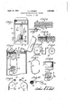
.April 12, 1932. A. c. ECKERT 1,853,895
I I hm Q I /6 7 v TALKING MACHINE AND RECORD THEREFOR Filed Nov. 2, 1928 f qqm bnmmm /0\ /Z r mam- Patented Apr. 12, 1932 ARTHUR G. EG KERT, OF ST. IDUIS, MISSOURI TALKING CHINE AND RECQBD THEREFOR Application filed November 2, 192a. seri ixo. 816,788.
UNITED STATES, PATENT orF cE The object of my device is to make a talking machine such as the modern raphophone, in which a record tape will e used instead of the conventional record. In the 5 use of the conventional record it becomes necessary after one side of the record is played to reverse the record in order to lay the other side. There is likewise a de nite particular limitation in the vdiameter of records. For this reason it is not practical in the conventional machine to play continuously for a great length of timewithout breaking the continuity and without the effort of reversing and changing records. In 15 addition, the storing of numerous records is quite a problem. on account of their necessary size and weight, etc. With the device herein described, it, will be possible to play for many hours without any interruption whatsoever, and without any manual effort.
It will be ossible to play a complete opera continuous y without any manipulation.
My device employs the conventional sound box and tone arm and needle and may be 5- either spring or motor operated. It is made of few and simple parts, that lend themselves readily to multiple production and may be easily and cheaply made and easily and cheaply replaced.
A further object is to so construct the record tape that both sides may be used for the sound depression and that all points of both sides will be presented to the needle without any changing or turning of the tape.
tape, so as to preserve the proper tension on the tape over the area in which the tape comes in contact with the needle.
A still further object is to put a twist or turn-in the tape and have the twist or turn at the dependent suspended end and'to provide means for easil and simply loosening the ends of the tape, because in operation the tape is endless.
A still further object is to provide means for the facile storing of the tape with the greatest possible space efiiciency.
With these and other objects in view my invention has relation to certain novel fea- .3 A still further object is to motivate the.
tures of construction and arrangement of parts, as will be hereinafter more fully described, pointed out in the claims, and illustrated in the drawings in which:
. Fig. 1 a plan view of the top of a talkmg machme with the tonal arm sound box and needle illustrated, as well as the o era- Itively and externally visible portion 0 the record tape. I
Fig. 2 is a vertical sectional elevation on line 22 of Fig. 1.
Fig. 3 is a schematic view of the recordtape showing the driving spool and tension spool together with the rollers that hold the externally visible portion of the record tape in operative position. Fig. 4 is a section of the record tape showng the spirally sha ed sound depressions and the lateral slots or engagement with the driving and tension spools.
, Fig. 5 a front elevation of said spool together with its shaft and a conventional motor attached to the shaft.
. Fig. 6 shows an end elevation of the driv- 111%SPO01.
ig. 7 is aperspective view of the record tape showing the turn in the tape.
Fig. 8 is a fragment of the tape ends showin their jointure. I
ig. 9 is a storing spool for the tape with the tape shown in position.
Fig. 9a is a modified form of a construction that will permit the use of a tape at greatly increased length.
Fig. 9b is a schematic view of the driving and tension spools together with the record tape 16 when the latter is of the non-continuous type, showing a simple method of attaching the tape ends to the core of each spool. o
Fig. 90 is a cross section taken on the line Numeral 10 designates the talking machine cabinet having the to plate 11, the oscillating tone arm 12 and the rectangular tape opening 13.
Numeral 14 designates the sound box and l 15 the needle. The arts thus far described with the exception 0 the tape opening 13 are conventional.
-,positioned in the mac which is rectangular in shape and has the lateral slots 17 formed therein. Numeral 18 designates the sound depressions, which may be either of the vertical or lateral type and when the ends of the record tape are joined together, as will be subsequently described, the sound depressions 18 will be formed spirally, that is to say, they will proceed from one side around the entire tape and on both sides of it to the other side of the tape. Mounted within the cabinet 10 on the shaft 19 is positioned the driving spool 20. This driving spool 20 is best illustrated in Figures 5 and 6 and is formed of the core 21 and the serrated disks 22,. which are symmetrically secured at the ends of the core 21. Mounted within the machine cabinet 10 is the motor 23. which may be either a spring motor or an electric motor, the driving shaft of which is connected directly to the shaft 19. It will be seen, therefore, that when the motor 23 is operated that the driving spool 20 will be rotated. Numeral 24 deslgnates a tension spool, which is rotatively mounted on the shaft 25, which shaft is mounted in the machine cabinet 10, as indicated in Fig. 2. The tension spool 24 is of the same shape and size as the driving spool 20 and has serrated disks having teeth of the same pitch as the teeth on the serrated disks 22. Numeral 26 designates a roller rotatively positioned in the machine cabinet 10, immediately adjacent one end of the tape opening 13 and extending across the opening and being slightly greater in width, than the width of the record tape 16. Numeral 27 desi ates a roller similarly ine cabinet 10, but at the opposite end, of the tape opening 13. The record tape 16 is positioned over the rollers 26 and 27 and over the tension spool 24 and the driving spool 20, so that the teeth of the serrated disks of the tension spool 24 and of the driving spool 20 are in mesh with the lateral slots 17 of the record tape 16. The ends of the record tape 16 are not joined directly, but a simple turn is made in the tape before the jointure is effected. This turn is particularly shown in Figure 7. The ends of the record tape 16 are then joined as are the ends of a power belt, but preferably so that there is a positive continuity between the surfaces of the belt ends. This may be accomplished by having eyes 28 secured to one end and perforated projections 29 secured to the other end. Numeral 30 designates a pin, which passes through the eyes 28 and the perforated projections 29, thereby securing the jointure' between the record tape ends without making the ointure rigid and permitting the efficient passing of the tape, over the driving spool 20 and the tension spool 24. In order to disturb the continuity of the sound depressions 18 as little as possible, there may be formed on one of the belt ends a flap which will cover the juncture between the belt ends. In that event the sound depressions 18 would be made in this flap.
In the event that it is desired to have the tension spool 24 and driving spool 20 as well as the rollers 26 and 27 removable, it is not necessary to have a selective juncture between the belt ends. The juncture may then be made by gluing or other methods, which will not disturb the continuity of the sound depressions 18 to any extent. It will be seen thatwhen the motor 23 is operated that the driving spool 20 will pull the record tape 16 by virtue of the contact of the teeth of the serrated disks 22 in the slots 17 over and around the rollers 27 and 26 and will rotate the tension spool 24 by virtue of a similar con-- tact. By a'proper positioning of the record tape 16 on the tension spool 24, the tension of the record tape between the rollers 26 and 27 may be regulated. If it is desired to have a positive support for the record tape while it is passing over the tape opening 13, a plate 31 may be secured to the machine cabinet 10 leaving slots for the ingress and egress of the record tape in and out of slots in the top plate 11. It will be noted that owing to the turn in the record tape 16, which turn will always remain below the tension spool 24 and the driving spool 20 that every point on both sides of the record tape 16 will pass over the tape opening 13. The direction of rotation of the record tape 16 is shown by the arrow in Fig. 1. When this tape is rotating, as indicated, and the sound box, oscillating arm and needle are placed in their operative position with the needle in one of the sound depressions 18, all of the sound depressions on both sides of the record tape will come in contact with the needle 15, since the sound depressions are continuous and are of spiral formation and on account of the turn in the record tape 16. The oscillating tone arm 12, will then be oscillated in the conventional manner by the travel of the needle 15 in sound depressions 18 and in a clock-wise direction in Fig. 1.
Since there is practically no limit to the length that the record tape may have in the talking machine cabinet, and since both sides are utilized, it is easily seen that there is no particular limit to the linear extent of the sound depressions 18. In order to further increase the length of the record tape, however, several idler rollers 32 and 33 may be secured in the cabinet 10 on the shafts 34 and 35, as shown in dash lines in Fig. 2. The tape may be passed over these idler rollers as shown by the dash lines in Fig. 2. The record tape may be made of celluloid, rubber, or any like material, which is thick enough and stable enough to receive the sound depressions 18 and which still will permit the slight bending that is necessary around the spool and rollers indicated.
My endless turned or twisted tape may have reproduce'it. A tape that does not have its ends joined together may be used. In this event one end of the tape may be secured to the core of the tension spool 24 in any conventional manner, as is the case of the con- I ventional photographic films, which is secured to a spool and the tape wrapped around the spool, as shown in Fig. 9b. The free end will then be passedover therollers 26 and 27 as was the case in the continuing tape heretofore described, and then secured to the core of the driving spool 20. -When the motor 23 is actuated, the tape will be drawn under the needle as in the case hereinbefore described and wra ped on the driving spool 20 and unwound i i-om the tension spool 24, as is the case in the music rolls 'in player pianos. The spools 20 and 24 in this instance must be removable from the shafts 19 and 25 or the a may be repeated for as many linear sound depressions as appear on one side of thetape. The driving spool may thenbe removed so that the reverse side of the spool will be presented to the needle 15. It will be observed that the same amount of music may be played from the non-continuous tape as from the continuous tape, but in the former it becomes necessary to reverse the spools at the end of every linear sound depression, while in the latter all the sound depressions may be played that appear on both sides without any interru tion and without any manual operation.
he term taple has been used here, but it is not intended t ereby expressly or implicitly to limitits width. A wide tape or sheet may be used. The length of the s iral sound depression varies directly with t e width of the tape and with its length.
n the instance of a non-continuous tape the sound depression may be linear and need not be spiral in form. The continuous tape need not interfere with the horn in the conventional talking machine cabinet for it may be suspended on the sides of the horn and the twist may be sus ended below the horn. For lengthening t e tape that is used, it is not intended to be limited to the method disclosed with the idler rollers 32 and 83. Another method that may be used is the following: The tape may be made to pass over and under bafile plates, as is shown in Fig. 9a in which the record tape 16 is made to pass under and over the bafile plates 36 which plates may be secured in the cabinet 10 in any conventional manner.
is not intended to limit the disclosure herein to the use of lateral slots 17 and serrated disks such as 22 for positive driving of the record tape 16. Any other conventional method may be used as spools without serrated disks or tapes having elevations laterally positioned for engagement with depressions in the spools 20 and 24.
What I claim and mean to secure by Letters Patent is 1. A record tape havin a twist therein and having lateral slots ormed thereon, a driving spool comprising a core and'serrated disks secured thereto, said tape in contact with said spool, so that the slots of said tape gill. be in mesh with the serrations on said 1s s. x I 2. A sound record tape having a twist therein and having lateral slots formed thereon, .a driving spool, comprising a core a and serrated disks secured thereto, said tape in contact with said spool, so that the slots of said tape will be in mesh with the serrations on said disks.
3. A record tape having and having slots formed t ereon, a driving spool, comprising a core and serrated disks, a tension spool comprising a core and serrated disks, both spools rotatively mounted, said tape assing in contact with said s ools so that t e serrations of the disks 0 said a twist therein spools will be in mesh with the slots in said record tape and means of rotating said driving spool.
4. A record tape having a twist therein and having slots formed therein, a driving spool comprisin a core, and serrated disks, a, tension spoo comprising a core and serrated spool.
In testimony whereof I aflix si ature. ARTHUR G. RT.
Priority Applications (2)
| Application Number | Priority Date | Filing Date | Title |
|---|---|---|---|
| US316763A US1853895A (en) | 1928-11-02 | 1928-11-02 | Talking machine and record therefor |
| US390966A US1853966A (en) | 1928-11-02 | 1929-09-07 | Talking machine and record therefor |
Applications Claiming Priority (1)
| Application Number | Priority Date | Filing Date | Title |
|---|---|---|---|
| US316763A US1853895A (en) | 1928-11-02 | 1928-11-02 | Talking machine and record therefor |
Publications (1)
| Publication Number | Publication Date |
|---|---|
| US1853895A true US1853895A (en) | 1932-04-12 |
Family
ID=23230569
Family Applications (1)
| Application Number | Title | Priority Date | Filing Date |
|---|---|---|---|
| US316763A Expired - Lifetime US1853895A (en) | 1928-11-02 | 1928-11-02 | Talking machine and record therefor |
Country Status (1)
| Country | Link |
|---|---|
| US (1) | US1853895A (en) |
Cited By (1)
| Publication number | Priority date | Publication date | Assignee | Title |
|---|---|---|---|---|
| US2647750A (en) * | 1947-11-22 | 1953-08-04 | Armour Res Found | Twisted loop magnetic recorder |
-
1928
- 1928-11-02 US US316763A patent/US1853895A/en not_active Expired - Lifetime
Cited By (1)
| Publication number | Priority date | Publication date | Assignee | Title |
|---|---|---|---|---|
| US2647750A (en) * | 1947-11-22 | 1953-08-04 | Armour Res Found | Twisted loop magnetic recorder |
Similar Documents
| Publication | Publication Date | Title |
|---|---|---|
| US1853895A (en) | Talking machine and record therefor | |
| US1853966A (en) | Talking machine and record therefor | |
| US2944750A (en) | Tape recorder indicator attachment | |
| US1636133A (en) | Musical instrument | |
| US2372810A (en) | Constant speed drive for magnetic recorders | |
| US1655299A (en) | Cinematograph projection apparatus | |
| US1326864A (en) | Selective controlling apparatus for electric circuits | |
| US2525995A (en) | Recording and reproducing apparatus | |
| US1847282A (en) | Music writing machine | |
| US1358085A (en) | Automatic stop for visible records corresponding to sound-records | |
| US3225640A (en) | Musical toy | |
| US2420671A (en) | Magnetic recorder | |
| US1166925A (en) | Apparatus for recording and reproducing sound. | |
| US2084782A (en) | Animated motion picture machine | |
| US1725145A (en) | Student's telegraph | |
| JPS59107446A (en) | magnetic recording and reproducing device | |
| US998264A (en) | Electric music-sheet-feeding device for self-playing instruments. | |
| US2254547A (en) | Keyboard indicating device | |
| US2548981A (en) | Magnetic recorder and wire handling means therefor | |
| US1316109A (en) | recke | |
| US1884003A (en) | lichtman | |
| US3818505A (en) | Magnetic tape device with flexible head mounting and moving means | |
| US2225620A (en) | Moving picture machine | |
| US3255978A (en) | Tape end attacher for reels | |
| DE243764C (en) |