US1853956A - Dashpot controlled mechanism - Google Patents
Dashpot controlled mechanism Download PDFInfo
- Publication number
- US1853956A US1853956A US279150A US27915028A US1853956A US 1853956 A US1853956 A US 1853956A US 279150 A US279150 A US 279150A US 27915028 A US27915028 A US 27915028A US 1853956 A US1853956 A US 1853956A
- Authority
- US
- United States
- Prior art keywords
- lever
- dashpot
- coin
- diaphragm
- piston
- Prior art date
- Legal status (The legal status is an assumption and is not a legal conclusion. Google has not performed a legal analysis and makes no representation as to the accuracy of the status listed.)
- Expired - Lifetime
Links
Images
Classifications
-
- G—PHYSICS
- G07—CHECKING-DEVICES
- G07F—COIN-FREED OR LIKE APPARATUS
- G07F17/00—Coin-freed apparatus for hiring articles; Coin-freed facilities or services
- G07F17/04—Coin-freed apparatus for hiring articles; Coin-freed facilities or services for anthropometrical measurements, such as weight, height, strength
- G07F17/045—Coin-freed apparatus for hiring articles; Coin-freed facilities or services for anthropometrical measurements, such as weight, height, strength for weighing persons
Definitions
- This invention has reference to improvements in or relating to dashpot controlled mechanisms.
- the present invention has for its object the utilization for useful purposes of a portion of the energy normally dissipated in the dashpot.
- the invention consists of a dashpot controlled mechanism wherein the energy or part of the energy transmitted to the damping medium is utilized for producing a force which is employed for actuating or controlling a subordinate or auxiliary mechanism or device.
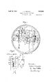
- Figure 1 is an elevation illustrating a dashpot control mechanism in accordance with the invention applied to a coin freed weighing apparatus of known construction sulficient only of which is shown as is necessary to an understanding of the invention.
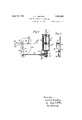
- Figure 2 is a part sectional elevation to an enlarged scale of the dashpot control mechanism shown in Figure 1.
- Figure 3 is a part sectional end elevation of a portion of the control mechanism seen in Figure 2.
- Figure 4 is a diagrammatic representation illustrating the application of the dashpot control mechanism to an electrically controlled coin freed mechanism.
- the coin freed weighing mechanism illustrated therein is of known kind wherein the pull of the load is taken to one arm of a lever 9 of the first order the other arm whereof has connection to a spring resistant 10 the outer end of the arm of the lever 9 to which the load is applied having a pivotal connection to a piston rod 11 the piston 12 carried whereby is adapted for reciprocation within the cylinder 12 of a fluid dashpot.
- the arm of the lever 9 to which the resistant 10 is attached is provided with a pin 13 adapted to move in a slot 1 1 formed in the upper end of a link 141: the lower end whereof is pivotally connected to a weighted lever 15 which, in turn, has pivotal connection to and carries a rack 16 adapted to mesh with a pinion 17 mounted on a spindie 18 carrying an indicating pointer (not shown) which registers with a graduated chart in known manner, the aforesaid weighted lever 15 normally tending to lift the rack 16 and actuate the indicating mechanism.
- the lower end of the dashpot cylinder 12 is provided with a cylindrical hole the walls whereof are tapped and engaged by the correspondingly threaded portion of a tubular well member 19 which is in communication with a pipe 20 the outer end whereof is fixed to a tubular bushing 21 fixed to one side of a hollow cylindrical diaphragm 22.
- the other side of the diaphragm 22 is connected to a rod 28 the other end whereof has a pivotal connection to a vertically disposed lever 25 adjacent the fulcrum thereof, said lever being fulcrumed on a plate 27 secured to the frame 28 and having its arc of motion limited by means of two stop pins 29 disposed on either side of the lever.
- the vertically disposed lever 25 is provided adjacent its upper end with a leaf spring 30 the upper end whereof is inwardly directed and located in the path of a horizontal projecting pin 31 fixed to one arm of a trip lever 32 which carries at its inner end a detent 33 adapted to co-operate with a one-way ratchet wheel 34 fixed on the spindle 18 carrying the indicating pointer,
- the other end of the lever 32 being provided with a platform 32 which is disposed within the coin chute 35 and in the path of a falling com.
- the operation of the invention is as follows WVhen the weighing apparatus is in the no load position the pin 13 on the lever 9 is located in the bottom of the slot 1 1 in the link 14 connected to the rack carrying lever 15 whereby the upward movementof the said rack carrying lever 15 and the consequential actuation of the indicating mechanism is prevented.
- the pin 13 moves in an upward direction and hence out of contact with the lower end of the slot 14L whereby the rack carrying lever 15 is free to move and raise the rack 16 in the event of the indicating spindle 18 being free.
- a portion of the energy thus transferred to the fluid medium is transmitted to the diaphragm 22 and from the diaphragm through the rod 23 to the vertically disposed lever 25 which is thereby caused to be maintained firmly pressed against the left hand stop
- This movement of the vertically disposed lever 25 locates the inwardly turned end of the leaf spring 30 above the projecting p n 31 on the trip lever 32 whereby a weight indication cannot be obtained until the lever32 is freed, that is, until a coin has been inserted.
- the weighing mechanism In the event of a load being removed before a coin is inserted the weighing mechanism would return to its zero position Without effecting the operation of the indicating mechanism. If a coin were inserted before the application of the load the lever 32 would be prematurely tripped but a weight indication would be obtained on the subsequent application of the load since the detent lever would be maintained by the spring 30 in its out of action position until the removal of a load thus'allowing of the indication of the weight to be obtained.
- the mechanism hereinbefore described ensures a positive control of the indicating mechanism of the weighing apparatus without involving any direct connection between the coin freed mechanism and the weighing apparatus whereby the accuracy and efficiency of the weighing apparatus is unimpaired by the said mechanism.
- the piston rod 11 of the dashpot mechanism is connected to a lever 9 of the weighing apparatus and the side of the dashpot 12 the more remote from the dashpot is connected to a rod 39 which in turn is pivotally connected to a lever 40 which is normally maintained in the vertical position by means of oppositely acting spring pressed plungers (not shewn).
- This lever 40 is providedat its upper end with contact members 40' adapted to cooperate with contacts 41 electrically connected with a solenoid 49.
- the solenoid 49 is oppositely wound relatively to a second solenoid 50 and the said solenoids 49 and 50 co-operate with a pair of armatures 17 and 48 which are secured to a vertically disposed plunger 46 which is pivotally connected at its upper end to the lever 9*.
- Disposed within the coin chute 45 is the tail of a trip lever 51 which is fulcrumedin bearings formed in a bracket carried at the upper end of the vertical arm of a bell crank lever 52.
- the other end of the trip'lever 51 is provided with a contact 51 which co-operates with a contact 52 carried by a cranked projection on the aforesaid bracket.
- the horizontal arm 52 of the bell crank lever rests on a ledge 46* projecting from the plunger 46.
- the contact point 51 of the trip lever 51 is normally maintained out of contact with the contact 52 by means of a spring (not shown).
- the solenoid 50 is in circuit with the contacts 51 and 52
- the insertion of a coin in the coin chute 45 rocks the lever 51 about its fulcrum and causes the contact 51 carried thereby to engage with the contact 52 and complete the circuit through the solenoid 50 whereby the plunger 46 is drawn upwardly.
- the upward movement of the plunger 46 causes the projection carried thereby to strike the horizontal arm 52 of the bell crank lever whereby the said bell crank lever turns about its pivot and moves the tail of the trip lever 51 out of its obstructing position in the coin chute thus allowing the coin to fall.
- the release of the coin can only take place in the event of the weighing apparatus being in equilibrium since if equilibrium is not attained varying pressure will be exercised by the piston in the dashpot 12 which will be transmitted to the diaphragm 22 thereby operating the contact lever 40 and completing the circuit through the solenoid 49 whereby the solenoid 49 will oppose the solenoid 50 and thus prevent the upward movement of the plunger 46 and hence the release of the trip lever 51 from its obstructing position within the coin chute 45.
- What I claim is 1.
- a movable member forming part of the primary mechanism of the weighing apparatus, a dashpot cylinder, a piston located within said cylinder and having connection with the said movable member, a fluid damping medium within the cylinder, a subordinate mechanism required to work in conjunction with the primary mechanism, a diaphragm in contact with the fluid damping medium and means for connecting the diaphragm to the subordinate mechanism whereby the said subordinate mechanism is operated upon the flexing of the diaphragm which obtains on the transference to the diaphragm of energy transmitted by the piston to the damping medium during the reciprocation of the piston when the weighing apparatus is out of equilibrium.
- a movable member forming part of the primary mechanism of the weighing apparatus, a dashpot cylinder, a piston located within said cylinder and having connection with the said movable member, a fluid damping medium within the cylinder, a hollow diaphragm the interior whereof is in communication with the dashpot cylinder, a subordinate mechanism required to work in conjunction with the primary mechanism and means connecting the said diaphragm to the subordinate mechanism whereby upon the flexing of the diaphragm due to the transference thereto of energy transmitted by the piston to the damping medium resulting from the reciprocation of the piston when the apparatus is out of equilibrium the connecting means is actuated and caused to effect the operation of the subordinate mechanism.
- a movable member forming part of the primary mechanism of the weighing apparatus, a dashpot cylinder, a piston located within said cylinder and connected to said movable member, a fluid damping medium within the cylinder, a diaphragm in contact with the damping medium, a subordinate mechanism required to work in conjunction with the primary mechanism and embodying as its controlling element a pivotal member and means connecting said pivotal member to the diaphragm so that he said member is actuated upon the flexing of the diaphragm as obtains when energy is transmitted to the diaphragm as the result of the reciprocation of the piston within the cylinder when the apparatus is out of equilibrium and caused to effect the operation of the subordinate mechanism.
Landscapes
- Physics & Mathematics (AREA)
- General Physics & Mathematics (AREA)
- Transmission Devices (AREA)
Description
April 12, 1932. c BRADLEY 1,853,956
DASHPO'I CONTROLLED MECHANISM Filed May 19, 1928 2 Sheets-Sheet l his florney April 12, 1932. Q BRADLEY 1,853,956
DASHPOT CONTROLLED MECHANISM Filed May 19 1928 2 Sheets-Sheet 2 Lake aflradley Patented Apr. 12, 1932 UNITED STATES PATENT OFFICE LESLIE CLIFFORD BRADLEY, OF BIRMINGHAM, ENGLAND, ASSIGNOR TO VT. & T. AVERY LIMITED, OF BIRMINGHAM, ENGLAND DASHPO'I CONTROLLED MECHANISM Application filed May 19, 1928, Serial No. 279,150, and in Great Britain June 7, 1927.
This invention has reference to improvements in or relating to dashpot controlled mechanisms.
In connection with fluid controlled dash- 6 pots of the cylinder and piston type it will be appreciated that the motion of the piston in the dashpot produces a variation in the pressure of the medium in the dashpot and it will be understood that in mechanisms of the lfi kind embodying such control it is frequently desired to utilize for some purpose a force which preferably should not be derived from direct connection with mechanism controlled by the dashpot. Such a condition of afiairs 15 arises in the case of coin freed weighing apparatus and analogous mechanisms wherein it is desirable that the coin freed mechanism or a subordinate or auxiliary mechanism or device should be entirely independent of the weighing mechanism or the like.
The present invention has for its object the utilization for useful purposes of a portion of the energy normally dissipated in the dashpot.
The invention consists of a dashpot controlled mechanism wherein the energy or part of the energy transmitted to the damping medium is utilized for producing a force which is employed for actuating or controlling a subordinate or auxiliary mechanism or device.
The invention will now be described with particular reference to the accompanying sheet of drawings, wherein Figure 1 is an elevation illustrating a dashpot control mechanism in accordance with the invention applied to a coin freed weighing apparatus of known construction sulficient only of which is shown as is necessary to an understanding of the invention.
Figure 2 is a part sectional elevation to an enlarged scale of the dashpot control mechanism shown in Figure 1.
Figure 3 is a part sectional end elevation of a portion of the control mechanism seen in Figure 2.
Figure 4: is a diagrammatic representation illustrating the application of the dashpot control mechanism to an electrically controlled coin freed mechanism.
In the drawings like numerals of reference indicate similar parts in the several views.
Referring first to the construction illustrated in Figures 1 to 3. The coin freed weighing mechanism illustrated therein is of known kind wherein the pull of the load is taken to one arm of a lever 9 of the first order the other arm whereof has connection to a spring resistant 10 the outer end of the arm of the lever 9 to which the load is applied having a pivotal connection to a piston rod 11 the piston 12 carried whereby is adapted for reciprocation within the cylinder 12 of a fluid dashpot. The arm of the lever 9 to which the resistant 10 is attached is provided with a pin 13 adapted to move in a slot 1 1 formed in the upper end of a link 141: the lower end whereof is pivotally connected to a weighted lever 15 which, in turn, has pivotal connection to and carries a rack 16 adapted to mesh with a pinion 17 mounted on a spindie 18 carrying an indicating pointer (not shown) which registers with a graduated chart in known manner, the aforesaid weighted lever 15 normally tending to lift the rack 16 and actuate the indicating mechanism.
The lower end of the dashpot cylinder 12 is provided with a cylindrical hole the walls whereof are tapped and engaged by the correspondingly threaded portion of a tubular well member 19 which is in communication with a pipe 20 the outer end whereof is fixed to a tubular bushing 21 fixed to one side of a hollow cylindrical diaphragm 22. The other side of the diaphragm 22 is connected to a rod 28 the other end whereof has a pivotal connection to a vertically disposed lever 25 adjacent the fulcrum thereof, said lever being fulcrumed on a plate 27 secured to the frame 28 and having its arc of motion limited by means of two stop pins 29 disposed on either side of the lever. The vertically disposed lever 25 is provided adjacent its upper end with a leaf spring 30 the upper end whereof is inwardly directed and located in the path of a horizontal projecting pin 31 fixed to one arm of a trip lever 32 which carries at its inner end a detent 33 adapted to co-operate with a one-way ratchet wheel 34 fixed on the spindle 18 carrying the indicating pointer,
the other end of the lever 32 being provided with a platform 32 which is disposed within the coin chute 35 and in the path of a falling com.
The operation of the invention is as follows WVhen the weighing apparatus is in the no load position the pin 13 on the lever 9 is located in the bottom of the slot 1 1 in the link 14 connected to the rack carrying lever 15 whereby the upward movementof the said rack carrying lever 15 and the consequential actuation of the indicating mechanism is prevented. Upon the application of a load to the weighing apparatus the pin 13 moves in an upward direction and hence out of contact with the lower end of the slot 14L whereby the rack carrying lever 15 is free to move and raise the rack 16 in the event of the indicating spindle 18 being free. Prior to the insertion of a coin, however the detent 33 on the trip lever 32 is in engagement with the ratchet wheel 34 and prevents the rotation of the indicating spindle in a counterclockwise direction as viewed in Figures 1 and 2 that being the direction of rotation which the rack 16 tends to impart to the said spindle 18. The movement of the resistant carrying lever 9, on the application of a load, is transferred to the piston 12 of the dashpot and results in an increase in pressure the fluid medium disposed below the said piston. A portion of the energy thus transferred to the fluid medium is transmitted to the diaphragm 22 and from the diaphragm through the rod 23 to the vertically disposed lever 25 which is thereby caused to be maintained firmly pressed against the left hand stop This movement of the vertically disposed lever 25 locates the inwardly turned end of the leaf spring 30 above the projecting p n 31 on the trip lever 32 whereby a weight indication cannot be obtained until the lever32 is freed, that is, until a coin has been inserted.
Upon the insertion of a coin the coin traverses the coin chute and in its path strikes the platform 32 of the trip lever 32 thereby rocking the said lever about its fulcrum. The impact of the coin is suflicient to enable the pin 31 to press back the spring 30 and free itself therefrom whereby the detent 33 is lifted out of contact with the ratchet wheel 34. and is prevented from engaging again the ratchet wheel owing to the pin 31 resting upon the top of the spring 30. The indicating spindle 18 is now free to move and under the action of the counterweight the rack carrying lever 15 is lifted until the lower end of the slot 14 in the link 14 again comes into contact with the pin 13 projecting from the resistant carrying lever 9 in which position the indicating pointer registers on the chart the measure of the load. On the removal of the load the fluctuation of the pressure in the dashpot cylinder 12 results in the suction effect of the oil acting on the diaphragm 22 and drawing the rod 23 connected to the vertical lever 25 towards the right hand stop 29 thereby removing the leaf spring 30 on the said lever from the path of the projection 31 whereupon the detent 33 falls under the action of gravity and a small tension spring. Simultaneously the resistant lever 9 returns to the zero position and the indicating pointer follows since the one-way motion of the detent and ratchet allow of the clockwise rotation of the indicating spindle. When the suction effect of the dashpot has subsided the flexibility of the diaphragm 22 causes the vertical lever 25 to resume its position against the left hand stop 29 as shewn in Figure 2.
In the event of a load being removed before a coin is inserted the weighing mechanism would return to its zero position Without effecting the operation of the indicating mechanism. If a coin were inserted before the application of the load the lever 32 would be prematurely tripped but a weight indication would be obtained on the subsequent application of the load since the detent lever would be maintained by the spring 30 in its out of action position until the removal of a load thus'allowing of the indication of the weight to be obtained.
It will be appreciated that the mechanism hereinbefore described ensures a positive control of the indicating mechanism of the weighing apparatus without involving any direct connection between the coin freed mechanism and the weighing apparatus whereby the accuracy and efficiency of the weighing apparatus is unimpaired by the said mechanism.
In the construction illustrated in Figure 4 the piston rod 11 of the dashpot mechanism is connected to a lever 9 of the weighing apparatus and the side of the dashpot 12 the more remote from the dashpot is connected to a rod 39 which in turn is pivotally connected to a lever 40 which is normally maintained in the vertical position by means of oppositely acting spring pressed plungers (not shewn). This lever 40 is providedat its upper end with contact members 40' adapted to cooperate with contacts 41 electrically connected with a solenoid 49. The solenoid 49 is oppositely wound relatively to a second solenoid 50 and the said solenoids 49 and 50 co-operate with a pair of armatures 17 and 48 which are secured to a vertically disposed plunger 46 which is pivotally connected at its upper end to the lever 9*. Disposed within the coin chute 45 is the tail of a trip lever 51 which is fulcrumedin bearings formed in a bracket carried at the upper end of the vertical arm of a bell crank lever 52. The other end of the trip'lever 51 is provided with a contact 51 which co-operates with a contact 52 carried by a cranked projection on the aforesaid bracket. The horizontal arm 52 of the bell crank lever rests on a ledge 46* projecting from the plunger 46. The contact point 51 of the trip lever 51 is normally maintained out of contact with the contact 52 by means of a spring (not shown). The solenoid 50 is in circuit with the contacts 51 and 52 The insertion of a coin in the coin chute 45 rocks the lever 51 about its fulcrum and causes the contact 51 carried thereby to engage with the contact 52 and complete the circuit through the solenoid 50 whereby the plunger 46 is drawn upwardly. The upward movement of the plunger 46 causes the projection carried thereby to strike the horizontal arm 52 of the bell crank lever whereby the said bell crank lever turns about its pivot and moves the tail of the trip lever 51 out of its obstructing position in the coin chute thus allowing the coin to fall. The release of the coin can only take place in the event of the weighing apparatus being in equilibrium since if equilibrium is not attained varying pressure will be exercised by the piston in the dashpot 12 which will be transmitted to the diaphragm 22 thereby operating the contact lever 40 and completing the circuit through the solenoid 49 whereby the solenoid 49 will oppose the solenoid 50 and thus prevent the upward movement of the plunger 46 and hence the release of the trip lever 51 from its obstructing position within the coin chute 45.
It will be understood that the invention is not limited to the applications described herein as it is equally applicable to other forms of dashpot controlled mechanism.
What I claim is 1. In combination with weighing apparatus a movable member forming part of the primary mechanism of the weighing apparatus, a dashpot cylinder, a piston located within said cylinder and having connection with the said movable member, a fluid damping medium within the cylinder, a subordinate mechanism required to work in conjunction with the primary mechanism, a diaphragm in contact with the fluid damping medium and means for connecting the diaphragm to the subordinate mechanism whereby the said subordinate mechanism is operated upon the flexing of the diaphragm which obtains on the transference to the diaphragm of energy transmitted by the piston to the damping medium during the reciprocation of the piston when the weighing apparatus is out of equilibrium.
2. In combination with weighing apparatus a movable member forming part of the primary mechanism of the weighing apparatus, a dashpot cylinder, a piston located within said cylinder and having connection with the said movable member, a fluid damping medium within the cylinder, a hollow diaphragm the interior whereof is in communication with the dashpot cylinder, a subordinate mechanism required to work in conjunction with the primary mechanism and means connecting the said diaphragm to the subordinate mechanism whereby upon the flexing of the diaphragm due to the transference thereto of energy transmitted by the piston to the damping medium resulting from the reciprocation of the piston when the apparatus is out of equilibrium the connecting means is actuated and caused to effect the operation of the subordinate mechanism.
3. In combination with weighing apparatus a movable member forming part of the primary mechanism of the weighing apparatus, a dashpot cylinder, a piston located within said cylinder and connected to said movable member, a fluid damping medium within the cylinder, a diaphragm in contact with the damping medium, a subordinate mechanism required to work in conjunction with the primary mechanism and embodying as its controlling element a pivotal member and means connecting said pivotal member to the diaphragm so that he said member is actuated upon the flexing of the diaphragm as obtains when energy is transmitted to the diaphragm as the result of the reciprocation of the piston within the cylinder when the apparatus is out of equilibrium and caused to effect the operation of the subordinate mechanism.
In testimony whereof I have signed my name to this specification.
LESLIE C. BRADLEY.
Applications Claiming Priority (1)
| Application Number | Priority Date | Filing Date | Title |
|---|---|---|---|
| GB1853956X | 1927-06-07 |
Publications (1)
| Publication Number | Publication Date |
|---|---|
| US1853956A true US1853956A (en) | 1932-04-12 |
Family
ID=10892025
Family Applications (1)
| Application Number | Title | Priority Date | Filing Date |
|---|---|---|---|
| US279150A Expired - Lifetime US1853956A (en) | 1927-06-07 | 1928-05-19 | Dashpot controlled mechanism |
Country Status (1)
| Country | Link |
|---|---|
| US (1) | US1853956A (en) |
-
1928
- 1928-05-19 US US279150A patent/US1853956A/en not_active Expired - Lifetime
Similar Documents
| Publication | Publication Date | Title |
|---|---|---|
| US1853956A (en) | Dashpot controlled mechanism | |
| US2067743A (en) | Weighing device | |
| US929281A (en) | Muscle-testing machine. | |
| US2981817A (en) | Switch | |
| US3142743A (en) | Momentary actuator for precision snap switch | |
| US2316627A (en) | Computing device | |
| US1533101A (en) | Dashpot mounting | |
| US2049632A (en) | Bathroom scale | |
| US728275A (en) | Coin-operated weighing-machine. | |
| US2724585A (en) | Drive for auxiliary load printing and indicating mechanism | |
| US2980251A (en) | Weighing machine | |
| US1802486A (en) | Refrigerating apparatus | |
| US1706539A (en) | Advertising scale | |
| US1889948A (en) | Protective device for scales | |
| US1398708A (en) | Weighing-scale | |
| US2285926A (en) | Weighing scale | |
| US1109091A (en) | Time-limit control for circuit-breakers. | |
| GB152481A (en) | Attachment for punching machines | |
| US2906519A (en) | Arresting mechanism for analytical balances | |
| US792694A (en) | Coin-controlled weighing-machine. | |
| US775309A (en) | Exercising device. | |
| GB182665A (en) | Improvements in or relating to weighing scales | |
| US1896283A (en) | A cokporation of new jebsey | |
| US1433738A (en) | Weight-indicating mechanism | |
| US1848833A (en) | Automatic weighing device |