US1853953A - Tuned electrical circuits - Google Patents
Tuned electrical circuits Download PDFInfo
- Publication number
- US1853953A US1853953A US319061A US31906128A US1853953A US 1853953 A US1853953 A US 1853953A US 319061 A US319061 A US 319061A US 31906128 A US31906128 A US 31906128A US 1853953 A US1853953 A US 1853953A
- Authority
- US
- United States
- Prior art keywords
- circuit
- tuned
- tuning
- oscillator
- current
- Prior art date
- Legal status (The legal status is an assumption and is not a legal conclusion. Google has not performed a legal analysis and makes no representation as to the accuracy of the status listed.)
- Expired - Lifetime
Links
Images
Classifications
-
- G—PHYSICS
- G01—MEASURING; TESTING
- G01R—MEASURING ELECTRIC VARIABLES; MEASURING MAGNETIC VARIABLES
- G01R27/00—Arrangements for measuring resistance, reactance, impedance, or electric characteristics derived therefrom
- G01R27/02—Measuring real or complex resistance, reactance, impedance, or other two-pole characteristics derived therefrom, e.g. time constant
- G01R27/26—Measuring inductance or capacitance; Measuring quality factor, e.g. by using the resonance method; Measuring loss factor; Measuring dielectric constants ; Measuring impedance or related variables
- G01R27/2688—Measuring quality factor or dielectric loss, e.g. loss angle, or power factor
Definitions
- H is Attorn zy
- the present invention relates to tuned electrical circuits, and has for its principal object to provide an improved apparatus and method of operation'whereby the resonance tuned circuits may be quickly and easily determined independently of their sharpness of resonance and of the amplitude oftheir response. 10
- the method and means of the present invention are particularly adapted to the testing of resonant circuits and component parts thereof, such as the coils andtuning condensers of radio broadcast receivers for example, in large quantity production, al-
- Fig. 1, 5 is an electric 'discharge device having associated grid and arlpde coils 6 and 7 respectively, which are. tuned by a rotary variablecondense'r' 8' to provide a common form of oscillator or oscillation generator havin a. frequency range determined by vthe re ation between the inductance of the coilsand the capacity of condenser 8.
- the electric discharge device is of the 3-e ement type and is su plied with operating volt ages'from suita le means such as a cathode heating battery 9, grid bias battery 10 and anode battery 11.
- Condenser- 8 is shunted by a variable condenser 12' by which its range may beadjusted for purposes hereinafter described.
- variable tuning means such as condenser 8 whereb' lts frequency output may be varied throug a desired frequency range, represents any suitable source
- the tuning means is most easily provided by a rotary variable condenser which is of a wellknown type having 180 degree tuning This should however be taken as representing any suitable means for varying the source of alternating current through its range of frequencies.
- the oscillator tunin means is continuously rotated by a suitab e small electric motor 13' which is connected with the condenser .shaft by an insulated coupling 14.
- oscillator or source of alternating current is thus caused to generate a frequency which is continuously varying between certain higher and lower limits as determined in the present example by the relative sizes of inductance and capacity used therein.
- the detector is an electric discharge device of the same typeas oscillator 5 and is supplied from the same voltage and current I sources as the oscillator, as indicated, although it may be of any suitable type and receive operating current and voltages from other sources.
- the beam of light from mirror 23 of the galvanometer originates in a suitable source such as a lamp 29 and is directed on mirror 23 through a lens 30 and a stationary deflect-' ing mirror 31, as indicated by dotted lines 32-33.
- a suitable source such as a lamp 29
- the beam of light 24 is adjusted in such a manner that it is directed upon the center of the screen at the junction 34 of the lines 28.
- Mirror 26 is mounted on a shaft 35 carried in suitable bearings 36 and coupled with the variable tuning means for the oscillator through a coupling 37 with the motor, to rotate in synchronism with the former.
- the mirror rotates in the direction of the light beam and the angular relation between the oscillator tuning means or rotor of condenser 8, and the mirror 26, is such that the mirror meets the beam of light 24 and refiects'it on to screen 27 while the oscillator tuning means passes through its tuning range which in the present example is 180 degrees, but is turned away from .the beam while the tuning means is returning through the remaining 180 degrees to the starting point.
- Mirror 26 is thus in efiect a cut-'ofi means which operates in synchronism with the oscillator tuning means to prevent the current responsive means or galvanometer from indicating a response except during the time when the oscillator tuning means is varying the oscillator through its frequency range in the desired direction. such as from a mini mum frequency to the maximum frequency.
- cut-ofi' means may be used with other forms of current respon'sive devices, although the arrangement shown in the present example is that now preferred because of its simplicity and read adaptability for coupling with a rotary osci lator tuning means such as condenser 8.
- Coil 15-16 is theinductance forming one component of a tunedcircuit 38.
- this circuit including inductance 15-16, is connected with a tuning means such as a variable capacity indicated at 39 a resonant tun-ed circult is provided, and with the arrangement shown this circuit then becomes "a selective coupling means between the source of alternating current or theoscillator and the detector or rectifier. Energy is then transmitted to the latter only at the frequency to which the resonant circuit is. tuned by the means connected-with the inductance 15-16.
- Circuit 38 may thus represent a.
- ,tune circuit 38 is arranged for testing the capacity component thereof which is the variable capacity 39.
- This is a standard three-unit variable condenser comprising three separate rotors 40 adjustably secured to a common shaft 41, by set screws 42 or other suitable means whereby their angular relation to each other maiy be adjusted.
- the shaft is journaled in a rame 43, which also carries three insulated stators 44 with which the rotors mesh.
- This tuned capacity is typical of the usual single controlled tuning means at present tuning a plurality of circuits simultaneously.
- each section of the tuning capacity is arranged to tune acircuit such as circuit 38, including an inductance similar to 15-16, to the same frequency for any an-' gular movement of the shaft 41.
- each section of the tuning capacity must be substantially identical with the others.
- the several sections of a multiple tuning means such as capacity 40 are not electrically identicaljand require adjustment after manufacture, and. in order that production may be rapid it is necessary that adjustment and correction be facilitated. It is to this phase of the manufacture that the apparatus of the present example is particu-. larly adapted, although it is not limited to the testin of the mutiple tuning means or of a con enser tuning means, but may be adapted to test any circuit tuning component located in a tuned circuit such as circuit 38, or in testing the response of the circuit itself.
- This means comprises a commutator or selective switching means 45 carrying a contact segment 46 which is connected through a ring 47 and a brush 48 with one side of tuned circuit 38 which in this case is the high potential side thereof.
- Segment 46 occupiessubstantially of the circumference of the commutator.
- three brushes 49 Arranged in the path of segment 46, inequally spaced relation to each other about the circumference of the commutator, are three brushes 49 to each of which is connected one section of the face of the disc adjacent the periphery I three separate equal openings. The s is arranged to rotate in a plane at a right tuned, capacity through circuit leads indicated at 50.
- tuned circuit 38 is connected with the frame, shaft and rotors of capacity 40,.all of which are electrically connected together, the timing capacity/10 being what is commonly known as a grounded rotor type.
- each section of the capacity 40 is connected with tuned circuit 38 for substantially one-third of the revolution of the commutator which is connect-- ed to rotate with mirror 26 and the tuning means 8 for the oscillator through a suitable gearing 51.
- each shutter opening is preferably colored by suitable means. such as a piece of colored glass mounted therein, each opening having a different color, whereby the color of the beam of light is changed as the commutator rotates.
- the shutter is so connected with thecommutator that the beam of light 32 passesthrough a sep arate opening in the shutter while the commutator connects each section of the tuning capacity with tuned circuit 38.
- the operation is as follows: With'the inductance of coil 15-16 of a desired value to cooperate with each section of tuning capacity 40 in responding to a certain desired frequency or frequency range, and-with the oscillator designed to provide a frequency range which includes any frequency to which coil 1516 may betuned by capacity 40, the
- detector 17 and oscillator 5 are energized together with motor 13 and lamp 29. This causes the oscillator to pass successively through its range of frequencies while the separate sections of the tuning capacity 40 are successively connectedzwith tunedbircuit 38. At the same time the beam of light from light source 29 is successively changed in color for each section of the tuning capacity.
- the condenser unit or tuning capacity 40 is then adjusted for the one frequency, and may be ers from the tested for others in its range or it may be removed from the circuit an another substituted in its place for a similar test, without stopping the operation of the testing means described.
- curves 56 and 57 are frequency response curves plotted between current and frequency coordinates as indicated.
- the oscillator or source of alternating current passes through its frequency range there appears in the anode or output circuit 19 of the detector a current "inipulse repre sented by curve'56.
- This is a usual resonance impulse curvel and its nodalpoint or peak,
- The; rotating mirror 26 is so synchronizedwith tu'ningmeans 8 of the oscillator that portion 59- -59 only of curve 57 is shown on the screen 27, the re- 7 of mirror 26 which as herelnbefore described provides'a cut-off means for the galvanom- -eter or current res onsive device.
- condenser 12 of the oscillator is adjusted until it provides the peak re'son'ant frequenc of circuit 38 at the instant when the rotating mirror 26 is in a mid position with respect to its travelin the path of light beam 24. This throws the lines into the center of the screen and gives the full image of the lines thereon, each line being a different color when a suitable color disc or shutter. means such as 53 is provided.
- the oscillator is caused to pass through ts frequency range by motor 13 which is connected with it through shaft 61 on which shaft is also mounted an insulated make and break contact or segment 62, and an insulated collector ring 63 togetherwith an arm 64v carrying a light 65 which as the shaft rotates,
- the lam represents any suitable indicating means a apted to be rotated shaft in syfichronism with tuning meanf's' ;8.. i ,At 17 is the'detector or rectigz n ut ut, or anode circuit 19 and an output transformer 20 the secondary of which supplies operating current to a currentresponsive device 67 through a circuit which maybe traced through wires 68-69,
- a source of voltage such as a battery 75 havin a series connected current limiting resistor 6 which source supplies current to the current responsive device 67 when the make and break device 62 is open.
- this device. is shown in its closed position, so that. the
- the make and break device 62 is sy-nchron zed-with the oscillator tunin -means 8 so that as the oscillator iscarrie through itsoperating range the brush is in contact with segment 62 to short circuit the voltage source 7 5- through resistor 76 which prevents excessive drain from the bat- 1n the present example the current responsive device 67' is .a polarized relay, and it will beseen that'when contact device 62 is open, 'thecurrent' from battery or voltage source 75. will holdjhe relay in a closed po sition in one direction.
- This olding force is sufiiciently stron to overcome any signal or indicating im use received fromthe detector, whereby t e indicating or current re- .sponsive'device 67 is rendered inoperative during thetime when the oscillator is being returned to its zeroor starting point for'each its effect to the motor operated cut-oil means provided in the obvious, any 0 er suitable cut-ofi means adapted for use with a current responsive device such as polarized relay 67 may be used.
- the relay is arranged to light the lamp 65 by meansof its movable armature 77 and two contacts 78 with which the arm engages ateither end of its travel.
- the arm otrelay 67 is connected through a lead 79 and a brush 80: with the collector ring 63, which in turn is connected with one side of the lamp 65 as indicated.
- Thev opposite side of the lamp connects with the arm 64, shaft 61, contact ring 72, brush 71, lead 73 andwith contacts .7 8 of the relay through a lead 81.
- Shunted across leads 79 and'81 is a second battery or source of voltage 82 and a series current limiting' resistor 83 therefor.
- This arrangement operates to light the lamp 65 when the relay contact arm is in a mid position between contacts 78 as shown the current for lighting the lamp being supplied from battery or voltage source 82. -When the relay is actuated to revolution "of the motor. This is similar in apparatus of Fig. 1, and as is t occur. at 180 therefrom and off the scale, be-
- the detector is provided with a pick-up coil 84 which is adapted to receive energy from the oscillator or through a circuit 85 in which a coil 86 is coupled with the oscillator and a coil 87 is coupled with the detector coil 84.
- a detector receives an impulse through the Interposed between the oscillator and the detector, that is, in the present example between coils 87 and 84, is a timed circuit 88, which is to be tested for resonance, and the components of which are indicated at 89 and 90, the former being the tuning capacity and the latter being the tuning inductance.
- coil 90 is electromagnetically coupled with coils 87 and 84 whereby the tuned circuit provides a coupling means between the oscillaously varying over a range extending between predetermined higher and lower limits at pretor and the detector in a manner similar to that described in connection with Fig. 1.
- the lamp 65 is lighted as the armature of the device 67 fol-. lows the change in current through the zero point of the cycle as indicated at 60 of Fig. '3. The lamp will then appear as a spot of light in the'same position on the scale for each revolution of the motor 13.
- circuits I or circuit tuning means may then be tested by substituting such circuits or circuit tuning meansfor' those shown in 88, 89 and 90, and observing any change in the location of the spot of light on scale 66.
- a'current responsive device indicatingmeans 116 Ill igher and lower limits at predetermined regular intervals
- a-detector coupled'with said oscillator to receive energy therefrom
- an output circuit for. said detector a transformer in said output circuit, and an electro-resp'onsive findicating'f device connected with said transformer.
- a source ofalternating current means for varying the frequency of said source, a tuned electrical circuit, means connected in said circuit for receiving energy from said source. of alternating current, a detector coupled with said tuned circuit and provided with an output circuit, a current responsive device, means for connecting said output circuit with said current responsive device, indicating means including a mirror arranged to be actuated by said current responsive device, a screen, means for directing a beam of light from said mirror on to said screen, and means synchronized with said first named means for cutting oif said beam of light at predetermined intervals.
- a source of alternating current means for varying the frequency of said source, a tuned electricalcircuit, means connected in said circuit for receiving'energy from said source ofalternating current, a detector coupled with said tuned circuit and provided with an output circuit, a current responsive device, means for connecting said output circuit with said current responsive device, and indicating'm'eans including a cur-' rent source arrangedwto be controlled by said current responsive device, a scale, alamp arranged to move over said'scale in synchro nism with said frequency varying means and means including said second-named current source and said current responsive device for controlling the lighting of said lamp.
Landscapes
- Engineering & Computer Science (AREA)
- Power Engineering (AREA)
- Physics & Mathematics (AREA)
- General Physics & Mathematics (AREA)
- Testing Of Short-Circuits, Discontinuities, Leakage, Or Incorrect Line Connections (AREA)
Description
April 12, 1932.,
HVI.1BECH(EFQ TUNED ELECTRICAL CIRCUITS 2 Sheets-Sheet 1 Filed Nov. 13, 1928 v Invehtor: Howard LBeCke'T,
is A't torne y.
April 12, 1932. BECKER 1,853,953
' TUNED ELECTRICAL VCIRCUITS Filed Nov. 13,..1928 "2'SheetsSheet 2 Inventor:
Howard '1. Becker.
H is Attorn zy,
Patented A r. 12,1932
UNITED STATES PATENT v oFncE HOWARD I. BECKER, OF- SCHENECTALDY, NEW YORK, ASSIGNOR '10 GENERAL ELECTRIC v comramaa CORPORATION OF NEW YORK h frequency response or resonant peak of such- 'rUNEnfELEcmroALcmoUIrs a nomon filed November is, 1928. Serial No. 319,061. I
The present invention relates to tuned electrical circuits, and has for its principal object to provide an improved apparatus and method of operation'whereby the resonance tuned circuits may be quickly and easily determined independently of their sharpness of resonance and of the amplitude oftheir response. 10
The method and means of the present invention are particularly adapted to the testing of resonant circuits and component parts thereof, such as the coils andtuning condensers of radio broadcast receivers for example, in large quantity production, al-
though it is not limited thereto, but may be,
, a curve diagram illustrating one phase of the operation of the apparatus of Figs. 1 and 2.
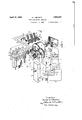
*5,- Referring to Fig. 1, 5 is an electric 'discharge device having associated grid and arlpde coils 6 and 7 respectively, which are. tuned by a rotary variablecondense'r' 8' to provide a common form of oscillator or oscillation generator havin a. frequency range determined by vthe re ation between the inductance of the coilsand the capacity of condenser 8. In the present exam is the electric discharge device is of the 3-e ement type and is su plied with operating volt ages'from suita le means such as a cathode heating battery 9, grid bias battery 10 and anode battery 11. Condenser- 8 is shunted by a variable condenser 12' by which its range may beadjusted for purposes hereinafter described.
movement.
The above described oscillation generator,
or oscillator having a variable tuning means such as condenser 8, whereb' lts frequency output may be varied throug a desired frequency range, represents any suitable source,
of electrical impulses or alternating current, the frequency of which may be varied through a desired range.
In connection: with the oscillator shown, the tuning means is most easily provided by a rotary variable condenser which is of a wellknown type having 180 degree tuning This should however be taken as representing any suitable means for varying the source of alternating current through its range of frequencies.
The oscillator tunin means is continuously rotated by a suitab e small electric motor 13' which is connected with the condenser .shaft by an insulated coupling 14. The
oscillator or source of alternating current is thus caused to generate a frequency which is continuously varying between certain higher and lower limits as determined in the present example by the relative sizes of inductance and capacity used therein.
Coupl'ed'to the oscillator through a divided coil 15-16 as hereinafter described, is a detector or rectifier 17. In the present example the detector is an electric discharge device of the same typeas oscillator 5 and is supplied from the same voltage and current I sources as the oscillator, as indicated, although it may be of any suitable type and receive operating current and voltages from other sources.
In this arrangement energy received from the oscillator by coil 15-16, is applied directly t0 the grid of the detector through a grid lead 18 connected with the high potential end of'the coil and providing conductive coupling therewith, although any other suitable coupling between the detector and the tuned circuit may be used.
Inthe anode or output circuit of the detector, which is indicated at 19, is connected a transformer 20, the secondary of which is connected with the terminals 21 of a galvanometer 22 representing any suitable current responsive device adapted for responding to current variations in the output circuit 19 light 24 through a lens 25 on to a rotating mirror 26 from which it is reflected to the surface of a translucent screen 27, the center of which is indicated by cross lines 28.
The beam of light from mirror 23 of the galvanometer originates in a suitable source such as a lamp 29 and is directed on mirror 23 through a lens 30 and a stationary deflect-' ing mirror 31, as indicated by dotted lines 32-33. When thegalvanometer is unexcited, with its mirror 23 in a normal centered position and with the rotating mirror 26 in a mid position relative to its rotation, the beam of light 24 is adjusted in such a manner that it is directed upon the center of the screen at the junction 34 of the lines 28.
It is obvious that other suitable cut-ofi' means may be used with other forms of current respon'sive devices, although the arrangement shown in the present example is that now preferred because of its simplicity and read adaptability for coupling with a rotary osci lator tuning means such as condenser 8.
Coil 15-16 is theinductance forming one component of a tunedcircuit 38. When this circuit, including inductance 15-16, is connected with a tuning means such as a variable capacity indicated at 39 a resonant tun-ed circult is provided, and with the arrangement shown this circuit then becomes "a selective coupling means between the source of alternating current or theoscillator and the detector or rectifier. Energy is then transmitted to the latter only at the frequency to which the resonant circuit is. tuned by the means connected-with the inductance 15-16. Circuit 38 may thus represent a. tuned circuit to be tested for resonanceor a test circuit in which the adjustment of either the inductance or capacity componentsto produce resonance at one point, or over a range of frequencies, may be determined by fixing the one component and adjustin the other. In the present example, ,tune circuit 38 is arranged for testing the capacity component thereof which is the variable capacity 39. This is a standard three-unit variable condenser comprising three separate rotors 40 adjustably secured to a common shaft 41, by set screws 42 or other suitable means whereby their angular relation to each other maiy be adjusted. The shaft is journaled in a rame 43, which also carries three insulated stators 44 with which the rotors mesh. This tuned capacity is typical of the usual single controlled tuning means at present tuning a plurality of circuits simultaneously. In such receivers each section of the tuning capacity is arranged to tune acircuit such as circuit 38, including an inductance similar to 15-16, to the same frequency for any an-' gular movement of the shaft 41. Hence each section of the tuning capacity must be substantially identical with the others.
Because of manufacturing variations which are unavoidable, the several sections of a multiple tuning means such as capacity 40 are not electrically identicaljand require adjustment after manufacture, and. in order that production may be rapid it is necessary that adjustment and correction be facilitated. It is to this phase of the manufacture that the apparatus of the present example is particu-. larly adapted, although it is not limited to the testin of the mutiple tuning means or of a con enser tuning means, but may be adapted to test any circuit tuning component located in a tuned circuit such as circuit 38, or in testing the response of the circuit itself.
With the multiple tuning unit shown, an arrangement is provided whereby each section thereof is successively "and separately connected into the tuned circuit 38, that is in the present example, in parallel with inductance 15-16. This means comprises a commutator or selective switching means 45 carrying a contact segment 46 which is connected through a ring 47 and a brush 48 with one side of tuned circuit 38 which in this case is the high potential side thereof. Segment 46 occupiessubstantially of the circumference of the commutator. Arranged in the path of segment 46, inequally spaced relation to each other about the circumference of the commutator, are three brushes 49 to each of which is connected one section of the face of the disc adjacent the periphery I three separate equal openings. The s is arranged to rotate in a plane at a right tuned, capacity through circuit leads indicated at 50.
The opposite or low potential side of tuned circuit 38 is connected with the frame, shaft and rotors of capacity 40,.all of which are electrically connected together, the timing capacity/10 being what is commonly known as a grounded rotor type.
With this arrangement each section of the capacity 40 is connected with tuned circuit 38 for substantially one-third of the revolution of the commutator which is connect-- ed to rotate with mirror 26 and the tuning means 8 for the oscillator through a suitable gearing 51. This gearing rovides a, 3: 1 ratio between the shaft by w 'ch the mirror and tuning means8 is drlven and a shaft 52 on which the commutator or selector means is mounted ,so thatveach section of the tuning capacity 40 remains in the tuned circuit 38 while the motor shaft makes one complete revolution, that is, while the oscillator tuning means 8 and the mirror 26 make one revolution. g I
Connected with the commutator 45, and in this case, mounted on the same shaft with it,
is a disc or shutter 53 having elongated open? ings or windows 54 equal in number to the number of sections of the tuning component 40, and of such length as to divide the sur'- into utter angle to the beam of light 32 so that the latter passes successively through the shutter openings as the shutter rotates. Each shutter opening is preferably colored by suitable means. such as a piece of colored glass mounted therein, each opening having a different color, whereby the color of the beam of light is changed as the commutator rotates. The
shutter is so connected with thecommutator that the beam of light 32 passesthrough a sep arate opening in the shutter while the commutator connects each section of the tuning capacity with tuned circuit 38.
The operation is as follows: With'the inductance of coil 15-16 of a desired value to cooperate with each section of tuning capacity 40 in responding to a certain desired frequency or frequency range, and-with the oscillator designed to provide a frequency range which includes any frequency to which coil 1516 may betuned by capacity 40, the
detector 17 and oscillator 5 are energized together with motor 13 and lamp 29. This causes the oscillator to pass successively through its range of frequencies while the separate sections of the tuning capacity 40 are successively connectedzwith tunedbircuit 38. At the same time the beam of light from light source 29 is successively changed in color for each section of the tuning capacity.
As a result of this, there appears on screen 27 three differently colored lines of light '55,
sti
three lines coincide on the screen; The condenser unit or tuning capacity 40 is then adjusted for the one frequency, and may be ers from the tested for others in its range or it may be removed from the circuit an another substituted in its place for a similar test, without stopping the operation of the testing means described.
It is obvious that while the above described arrangement is adapted for testin a three-unit tuning means, it is not limited thereto but may be used to test a tuning means having one section or any number of sections, the number of sec 'ons determining the number of pointson he switching means or commutator and'the number of windows on the'shutter. It is obvious that the shutter is notentirely necessary but is desirable since it permits the registrations or indications to be allocated to each section of the tuning means being tested by a difference in color of the light on screen 27. Likewise it is obvious to one skilled in the;-. .;art that since a tuned circuit comprises it uc'tance and capacity, that the means show I and adjusting a apacity tuning means alone, but thatit may be adapted to test in much the same manner, oneor more inductive tuning means by suitably interposing the tuned circuit containing such components between the source of alternat in%current and the detector.
eferring now to Fig. 3 along with Fig. 1, the reason for the above described operatnot limited to ing results will be further described. In
Fig. 3, curves 56 and 57 are frequency response curves plotted between current and frequency coordinates as indicated. Whenthe oscillator or source of alternating current passes through its frequency range there appears in the anode or output circuit 19 of the detector a current "inipulse repre sented by curve'56. This is a usual resonance impulse curvel and its nodalpoint or peak,
represents t nanoepoint of circu1t=ijj88 tuned by one ion of. capacity 40. This impulse produces in the secondary of transformer 20 and in the current responsive device 22 an alternating current cycle repre- I sented by curve 57 This cycle occurs each time the oscillator passes t rough the resonance point of the tuned circuit,- for each- 'm mainder of the curve being lost by operation section of the capacity 40 under test. The galvanometer-fol ows the current wave 'or cycle 57 for the resonance impulse of each section of capacity 40 and throws a beam of light across lens 25 between points which may be indicated at 58-58 Fig. 1 as it follows. each current'wave. The; rotating mirror 26 is so synchronizedwith tu'ningmeans 8 of the oscillator that portion 59- -59 only of curve 57 is shown on the screen 27, the re- 7 of mirror 26 which as herelnbefore described provides'a cut-off means for the galvanom- -eter or current res onsive device.
In order thatt e full length of portion 59-59. of curve 57 may appear on the screen as one of lines 55 for any particular setting of tuning capacity 40, condenser 12 of the oscillator is adjusted until it provides the peak re'son'ant frequenc of circuit 38 at the instant when the rotating mirror 26 is in a mid position with respect to its travelin the path of light beam 24. This throws the lines into the center of the screen and gives the full image of the lines thereon, each line being a different color when a suitable color disc or shutter. means such as 53 is provided.
I By examining the curves in Fig. 3 it will be seen that the peak of curve 56 represents the exactresonance point fortuned circuit 38 and thatregardless of its sharpness or amplitude, by the use of transformer 20in the circuit in which this resonance wave is detected, there will result an alternating current wave 57 having a zero point indicated at 60, which will always directly coincide with the peak frequency of the tuned circuit 38. It serves therefore as an accurate indication of the resonance point of the tuned.
circuit or, of the resonance adjustment of the tuning component therein. Hence, in
.the present example the simultaneous indioscillations which is tuned by-condenser 8.
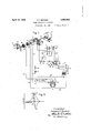
connected with its grid -coil f5, while 9 10 and 1-1 are the sources respectlvely of filament current, grid bias voltage and anode voltage. The oscillator is caused to pass through ts frequency range by motor 13 which is connected with it through shaft 61 on which shaft is also mounted an insulated make and break contact or segment 62, and an insulated collector ring 63 togetherwith an arm 64v carrying a light 65 which as the shaft rotates,
passes over a scale 66. The lam represents any suitable indicating means a apted to be rotated shaft in syfichronism with tuning meanf's' ;8.. i ,At 17 is the'detector or rectigz n ut ut, or anode circuit 19 and an output transformer 20 the secondary of which supplies operating current to a currentresponsive device 67 through a circuit which maybe traced through wires 68-69,
a brush 70 hearing on contact 62, through the a shaft 61- and returning through" a brush 7 J. bearing on a'suitable contact ring 72 on the shaft,and wires 7 3 and 7f Shunted across wires 69 and 73 is a source of voltage such as a battery 75 havin a series connected current limiting resistor 6 which source supplies current to the current responsive device 67 when the make and break device 62 is open. In the present example this device. is shown in its closed position, so that. the
battery or voltage source is inoperative to affect the circuit containing the current responsive device! The make and break device 62 is sy-nchron zed-with the oscillator tunin -means 8 so that as the oscillator iscarrie through itsoperating range the brush is in contact with segment 62 to short circuit the voltage source 7 5- through resistor 76 which prevents excessive drain from the bat- 1n the present example the current responsive device 67' is .a polarized relay, and it will beseen that'when contact device 62 is open, 'thecurrent' from battery or voltage source 75. will holdjhe relay in a closed po sition in one direction. This olding force is sufiiciently stron to overcome any signal or indicating im use received fromthe detector, whereby t e indicating or current re- .sponsive'device 67 is rendered inoperative during thetime when the oscillator is being returned to its zeroor starting point for'each its effect to the motor operated cut-oil means provided in the obvious, any 0 er suitable cut-ofi means adapted for use with a current responsive device such as polarized relay 67 may be used.
The relay is arranged to light the lamp 65 by meansof its movable armature 77 and two contacts 78 with which the arm engages ateither end of its travel. The arm otrelay 67 is connected through a lead 79 and a brush 80: with the collector ring 63, which in turn is connected with one side of the lamp 65 as indicated. Thev opposite side of the lamp connects with the arm 64, shaft 61, contact ring 72, brush 71, lead 73 andwith contacts .7 8 of the relay through a lead 81. Shunted across leads 79 and'81 is a second battery or source of voltage 82 and a series current limiting' resistor 83 therefor. This arrangement operates to light the lamp 65 when the relay contact arm is in a mid position between contacts 78 as shown the current for lighting the lamp being supplied from battery or voltage source 82. -When the relay is actuated to revolution "of the motor. This is similar in apparatus of Fig. 1, and as is t occur. at 180 therefrom and off the scale, be-
ing removed by operation of the contact making device 62 as hereinbefore explained.
The arrangement above described is substantially the same as that described in connection with Fig. 1 except that the present arrangement is simplified for use with a single tuned circuit to be tested instead of a plurality thereof, and employs a different type of current responsive device and cut-off means therefor. 1
The detector is provided with a pick-up coil 84 which is adapted to receive energy from the oscillator or through a circuit 85 in which a coil 86 is coupled with the oscillator and a coil 87 is coupled with the detector coil 84.
' tween the oscillator and the detector.
detector receives an impulse through the Interposed between the oscillator and the detector, that is, in the present example between coils 87 and 84, is a timed circuit 88, which is to be tested for resonance, and the components of which are indicated at 89 and 90, the former being the tuning capacity and the latter being the tuning inductance. In the present example as indicated by lines 91, coil 90 is electromagnetically coupled with coils 87 and 84 whereby the tuned circuit provides a coupling means between the oscillaously varying over a range extending between predetermined higher and lower limits at pretor and the detector in a manner similar to that described in connection with Fig. 1.
Totest the resonance point of circuit 88 or to test the effect of variation in either of its components, it is brought into position to form a suitable coupling as indicated, be-
As the tuned circuit, and applies through transform er 20 an alternating current cycle to the current responsive device 67, the lamp 65 is lighted as the armature of the device 67 fol-. lows the change in current through the zero point of the cycle as indicated at 60 of Fig. '3. The lamp will then appear as a spot of light in the'same position on the scale for each revolution of the motor 13.
. Supposedly identical circuits I or circuit tuning means may then be tested by substituting such circuits or circuit tuning meansfor' those shown in 88, 89 and 90, and observing any change in the location of the spot of light on scale 66.
. From the foregoing description of the embodiments of the inventionshownin the pres:
' ent example it will be seen thatthe method testing the manufactured components of tuned circuits such as coils and the condensers in production, and that the method is applicable to the testing of such circuits inde- 1 pendently of their sharpness of resonance or of the amplitude of the-resonanceresponse.
What I claim as new and desire-"to" secure" by Letters Patent of the-United'States, is:
1. The combination with a tunedelectrical circuit, of means for generating electrical os-. cillatlons having frequencies continuously varyingover a certain range at predetermined regular intervals, said rangeof frequencies including a frequency resonant with the" frequency to whichsaid circuit is tuned, means for recelving oscillations from sald generating means through said tuned circuitat' theresonant frequency of said circuit and-for rectlfylng .said osclllatlons, and means. con.-
nected with said receiving and rectifying means for indicating the nodal points ofsaid rectified impulses. y
. 2. The combination with a tuned electrical circuit, of means'for applying thereto electrical i'mpulseshaving frequencies continutously varying betweenpredetermined higher determined regular intervals, said range of frequencies including a frequency resonant with the frequency to which said circuit'is tuned, a detector arranged to receive energy fromsaid circuit at the resonant frequency arranged to be actuated thereby, and means for connecting the output circuit of said detector with said device.
(v 1. The combination with a tuned electrical circuit, of an oscillatorcoupled'with said circjuit for applying electrical impulses thereto, means for varying the frequency'of said impulses continuously between predetermined thereof and provided'with an output circuit,
" a'current responsive device, indicatingmeans 116 Ill igher and lower limits at predetermined regular intervals, a-detector coupled'with said oscillator to receive energy therefrom, an output circuit for. said detector, a transformer in said output circuit, and an electro-resp'onsive findicating'f device connected with said transformer. j
i 5'. The combination with a tuned electrical circuit, of an oscillator coupled with said circuits for applying energy thereto, means for varying the output frequency of the oscillator, a detector coupled with said oscillator to receive energy therefrom, an output circuit for said detector, a transformer in said output circuit, a current res onsive device con;
nected with said trans ormer, indicating current, a tuned electrical circuit, means for continuously varying the frequenc of said source over a certain range at reg'u ar intervals, said range of frequencies including a. frequency resonant with the frequency of said tuned circuit, means in said circuit for receiving energy from said source of alternattuned circuit and provided with an output circuit, a current responsive device, means for connecting said output circuit with said current res onsive device, and indicating means arrange to be actuated by said current responslve device. 1
7. In combination, a source ofalternating current, means for varying the frequency of said source, a tuned electrical circuit, means connected in said circuit for receiving energy from said source. of alternating current, a detector coupled with said tuned circuit and provided with an output circuit, a current responsive device, means for connecting said output circuit with said current responsive device, indicating means including a mirror arranged to be actuated by said current responsive device, a screen, means for directing a beam of light from said mirror on to said screen, and means synchronized with said first named means for cutting oif said beam of light at predetermined intervals.
8. In combination, a source of alternating current, means for varying the frequency of said source, a tuned electricalcircuit, means connected in said circuit for receiving'energy from said source ofalternating current, a detector coupled with said tuned circuit and provided with an output circuit, a current responsive device, means for connecting said output circuit with said current responsive device, and indicating'm'eans including a cur-' rent source arrangedwto be controlled by said current responsive device, a scale, alamp arranged to move over said'scale in synchro nism with said frequency varying means and means including said second-named current source and said current responsive device for controlling the lighting of said lamp.
In witness whereof, Izhave hereunto'set. my
day of November, 1927.
hand this 12th HOWARD I. BECKER.
ingcurrent, a detector coupled withsaid
Priority Applications (1)
| Application Number | Priority Date | Filing Date | Title |
|---|---|---|---|
| US319061A US1853953A (en) | 1928-11-13 | 1928-11-13 | Tuned electrical circuits |
Applications Claiming Priority (1)
| Application Number | Priority Date | Filing Date | Title |
|---|---|---|---|
| US319061A US1853953A (en) | 1928-11-13 | 1928-11-13 | Tuned electrical circuits |
Publications (1)
| Publication Number | Publication Date |
|---|---|
| US1853953A true US1853953A (en) | 1932-04-12 |
Family
ID=23240695
Family Applications (1)
| Application Number | Title | Priority Date | Filing Date |
|---|---|---|---|
| US319061A Expired - Lifetime US1853953A (en) | 1928-11-13 | 1928-11-13 | Tuned electrical circuits |
Country Status (1)
| Country | Link |
|---|---|
| US (1) | US1853953A (en) |
Cited By (8)
| Publication number | Priority date | Publication date | Assignee | Title |
|---|---|---|---|---|
| US2418750A (en) * | 1942-09-04 | 1947-04-08 | Rca Corp | Signal detection system |
| US2450018A (en) * | 1943-05-07 | 1948-09-28 | Standard Telephones Cables Ltd | Radio monitoring system |
| US2471432A (en) * | 1944-08-11 | 1949-05-31 | Lewis F Jaggi | Wavemeter to calibrate panoramic receivers |
| US2500625A (en) * | 1946-06-14 | 1950-03-14 | Bell Telephone Labor Inc | System for measuring and eliminating impedance variations |
| US2502294A (en) * | 1943-08-19 | 1950-03-28 | Wallace Marcel | Double sweep panoramic radio receiver |
| US2525675A (en) * | 1946-05-07 | 1950-10-10 | Panoramic Radio Corp | Signal comparing system |
| US2559688A (en) * | 1947-07-24 | 1951-07-10 | Guy A D Touvet | Absorption spectrometry with use of radio-frequency modulated light source |
| US2561871A (en) * | 1947-03-22 | 1951-07-24 | Rca Corp | High-power transmission line switch |
-
1928
- 1928-11-13 US US319061A patent/US1853953A/en not_active Expired - Lifetime
Cited By (8)
| Publication number | Priority date | Publication date | Assignee | Title |
|---|---|---|---|---|
| US2418750A (en) * | 1942-09-04 | 1947-04-08 | Rca Corp | Signal detection system |
| US2450018A (en) * | 1943-05-07 | 1948-09-28 | Standard Telephones Cables Ltd | Radio monitoring system |
| US2502294A (en) * | 1943-08-19 | 1950-03-28 | Wallace Marcel | Double sweep panoramic radio receiver |
| US2471432A (en) * | 1944-08-11 | 1949-05-31 | Lewis F Jaggi | Wavemeter to calibrate panoramic receivers |
| US2525675A (en) * | 1946-05-07 | 1950-10-10 | Panoramic Radio Corp | Signal comparing system |
| US2500625A (en) * | 1946-06-14 | 1950-03-14 | Bell Telephone Labor Inc | System for measuring and eliminating impedance variations |
| US2561871A (en) * | 1947-03-22 | 1951-07-24 | Rca Corp | High-power transmission line switch |
| US2559688A (en) * | 1947-07-24 | 1951-07-10 | Guy A D Touvet | Absorption spectrometry with use of radio-frequency modulated light source |
Similar Documents
| Publication | Publication Date | Title |
|---|---|---|
| US2252058A (en) | Method and means for testing resonant circuits | |
| US2084760A (en) | System for radio spectrography | |
| US1853953A (en) | Tuned electrical circuits | |
| US2222943A (en) | Electron switching circuit | |
| US2089430A (en) | Oscillograph system | |
| US2321315A (en) | Frequency measuring system | |
| US2532731A (en) | Visualization of complex waves | |
| US2490899A (en) | Apparatus for determining the phase relation of sinusoidal electric signals | |
| US2349687A (en) | Electromagnetic-inspection system | |
| US2145483A (en) | Cathode ray oscilloscope | |
| US2426245A (en) | Time and distance measuring system | |
| US2760151A (en) | Cathode ray tube test circuit | |
| US2790142A (en) | Missing pulse indicator | |
| US2581211A (en) | Range tracking pulse echo system | |
| US2583173A (en) | Radar receiver | |
| US2086892A (en) | Frequency monitoring device | |
| US1934879A (en) | Frequency measuring system | |
| US2155280A (en) | Electric discharge apparatus | |
| US2501352A (en) | Controlling means for operating an electronic oscillograph to produce a record | |
| US2088478A (en) | Split-cycle timing device | |
| US2444151A (en) | Scanning receiver for detecting signals of unknown frequency | |
| US2058898A (en) | Electrooptical image production | |
| US2217326A (en) | Picture transmitter | |
| US2461998A (en) | Pulse echo system and pulse indicating means | |
| US2478670A (en) | Automatic register for echo pulses from a plurality of objects |