US1853919A - Reversible swinging wringer mechanism - Google Patents
Reversible swinging wringer mechanism Download PDFInfo
- Publication number
- US1853919A US1853919A US481940A US48194030A US1853919A US 1853919 A US1853919 A US 1853919A US 481940 A US481940 A US 481940A US 48194030 A US48194030 A US 48194030A US 1853919 A US1853919 A US 1853919A
- Authority
- US
- United States
- Prior art keywords
- shaft
- housing
- trigger
- wringer
- arm
- Prior art date
- Legal status (The legal status is an assumption and is not a legal conclusion. Google has not performed a legal analysis and makes no representation as to the accuracy of the status listed.)
- Expired - Lifetime
Links
Images

Classifications
-
- D—TEXTILES; PAPER
- D06—TREATMENT OF TEXTILES OR THE LIKE; LAUNDERING; FLEXIBLE MATERIALS NOT OTHERWISE PROVIDED FOR
- D06F—LAUNDERING, DRYING, IRONING, PRESSING OR FOLDING TEXTILE ARTICLES
- D06F45/00—Wringing machines with two or more co-operating rollers; Similar cold-smoothing apparatus
- D06F45/16—Details
- D06F45/18—Driving or control arrangements for rotation of the rollers
-
- Y—GENERAL TAGGING OF NEW TECHNOLOGICAL DEVELOPMENTS; GENERAL TAGGING OF CROSS-SECTIONAL TECHNOLOGIES SPANNING OVER SEVERAL SECTIONS OF THE IPC; TECHNICAL SUBJECTS COVERED BY FORMER USPC CROSS-REFERENCE ART COLLECTIONS [XRACs] AND DIGESTS
- Y10—TECHNICAL SUBJECTS COVERED BY FORMER USPC
- Y10T—TECHNICAL SUBJECTS COVERED BY FORMER US CLASSIFICATION
- Y10T74/00—Machine element or mechanism
- Y10T74/19—Gearing
- Y10T74/19219—Interchangeably locked
- Y10T74/19377—Slidable keys or clutches
- Y10T74/19414—Single clutch shaft
- Y10T74/19484—Single speed forward and reverse
- Y10T74/19493—Bevel gears
-
- Y—GENERAL TAGGING OF NEW TECHNOLOGICAL DEVELOPMENTS; GENERAL TAGGING OF CROSS-SECTIONAL TECHNOLOGIES SPANNING OVER SEVERAL SECTIONS OF THE IPC; TECHNICAL SUBJECTS COVERED BY FORMER USPC CROSS-REFERENCE ART COLLECTIONS [XRACs] AND DIGESTS
- Y10—TECHNICAL SUBJECTS COVERED BY FORMER USPC
- Y10T—TECHNICAL SUBJECTS COVERED BY FORMER US CLASSIFICATION
- Y10T74/00—Machine element or mechanism
- Y10T74/19—Gearing
- Y10T74/19502—Pivotally supported
- Y10T74/19521—Bevel
- Y10T74/1953—Wringer type
Definitions
- This invention relates to a novel andimproved reverse-gear swinging wringer mechanism for washing machines and the l1ke and consists of the matters hereinafter d escribed and more particularly pointed out- 1n the appended claims.'
- the object of the invention is to provide a simple, economical and eiiicient reverse-gear swinging wringer mechanism capable of being swung to any one of a predetermmed number of positions in which the wringer isv myspecication.
- Figure 1 is a view representing a vertical central section through 'the improved swinging wringer mechanism, with'the reverse gearing in neutral position and with the' control arm in that position which it occuples 4when the wringer isin one of its predetermined positions and is locked againstswinging movement.
- Figure 2 is a like View except that the conf trol arm has been shifted gto. perrnitV the wringer to be swung to a different positior Figure 3 vis, another like view with the control arm in position after shifting the ,clutchcommon tothe reverse-gears'from vneutral. to
- Figure 4 is a partialelevation ofa wash? ⁇ ing machine with -.Iny/ir'nproved mechanism applied thereto;
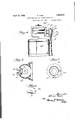
- Figure 5 is a horizontal cross section- ⁇ through the housing 0f the reverse-gearing in a plane indicated by the line 5--5 of Figure 1.
- v y y Figure' l is 'a plan view of a shaft operated by the control arm for shifting'the clutc of the reverse gearing.
- Figure 7 is a top plan view of a notched collar or fia-nge on the tubular post supporting the gearing, -the notches in said collar corresponding to the Vseveral predetermined positions of the wringer.
- anygfamiliar typen- 10 indicates the usual tubular bearing' standard adapted to be supported upon and to extend vertically alongside a power washing machine'tub 10a, containing'and providing bearing for a power driven vertical shaft 11.
- said standardj has a horlzontal radial flange or collar 12 which presents a base or support .for theswinging wringer mechanism indicated, as a whole by the numeral 13.
- a vertical shaft 17 has bearing in the tubular post 16 and depends therebelow to be cou led to the power driven operating shaft 11 y a diametric pin and slot connection -18 in 'a familiar manner.
- Said shaft 17 extends vertically through the Vhousing 14, which provides for it a top bear- .p Onsaid shaft are assembled the two' 20 and' 21, with'the movable h ycollar 22 between them for 'ecting the one or other to -both reverse gears engaging operating gear 23 which A'gen1-.all Vin a well known gearsv operativ the" shaft ⁇ 1 the p efwrnger 24.
- It contains a horizental;-bushing24et in which bears thel hollow-hub-23'L4 of the intermediate gear23.
- Said hollow hub is'designed to receive the end contains a polygonal lsocket 25 for locking vsaid wringer shaft tothe said intermediate Y 4racket-which directly supv' of theT driven shaft 24 jofthe wringer and p' tudinal movement inthe housing 14 in any familiar manner, as by a pin 26 taking through the top bearing 19 and engaging an annular groove 27 on the shaft.
- shaft 17 and the attached wringer may be 28 against any movement in a plane at right angles to said shaft 28 so that it may rock the shaft to shift the clutch collar.
- said control arm is capable when inQ'one positiony of a swinging movement in the plane of the shaft 28 away from the housing-as from the vertical position shown in Figure 1, to a position inclined away from the housing, as
- the housing adjacent the arm 31, is provided with a boss 32, which abuts' against the arm 31 in a semi-circular arc above the horizontal axis of the shaft 28, but is cut away below said axis, as indicated at 32a (Figs. 1 and 2) topermit the arm 31, when in vertical position, to be swung from the vertical position shown in Figure 1 to the position inclined away from the housing, shown in Figure 2. ⁇
- the'shaft 28 and its eccentric pin 29 are in position to hold the clutch collar 22 in neutral position.
- any other position of the arm 31 as when it has been swung into horizontal position, illustrated in Figure 3. to rock the shaft 28 and shift said clutch colla-r into operative engagement with one of the reverse gears 20, 21, the boss 32 will block any swinging movement of the arm 31 on its pivot pin 33.
- a plurality of notches 34 In the edge of thesupporting flange 12 of the vertical standard 10, there are provided a plurality of notches 34, the number of said notches depending upon the number of positions which the swinging wrmger is designed to occupy, each notch corresponding to 'one of said positions.
- a spring-controlled pivotedtrigger 36 In the vertical plane of theswinging movement of the arm 31 away .from the housing and immediately'below the shaft 28 on a horizontal pin 35 is mounted a spring-controlled pivotedtrigger 36.
- Said trigger is suitably placed in a vertical slot provided by parallel spaced'iribs 37 projecting from the housing, and as shown, depending from the boss 32. Insaid ribs the pin 35, placed intermediate the ends of the trigger, is fixed.
- the bottom end of the trigger 36 extends into the plane of the flange 12 of the standard for engagement with one of the notches 34 therein.
- Said trigger is held in engagement with the said i'ange 12by means of aball 38 and spring 38 mounted in a downwardly and outwardly inclined recessv39 in the rock shaft 28, with the ball in engagement with the upper end of the trigger.
- the housing 14 with the attached wringer 24c is swung on its vertical axis, as by the rotation of the post 16 in the standard 10 to bring the trigger 36 opposite one of said notches 34, said trigger will be forced by the spring into said notch and thus lock the housing Y against further rotative movement.
- Thecontrol arm 31 has a finger 40 which depends below the rock shaft 28 to the horizontal level of the upper end of the trigger 36 and above its pivot pin 35, when said arm is in its vertical position Corresponding with the neutral position ofthe clutch collar 22 lVhen in that position, and when in that position only, the arm 31 may be swung on its pivot 33 away from the housing,-that is to say, from the position shown in Figure 1 to the position shown in Figure 2. In this movement the finger 41 will depress the upper end of the trigger (against the action of the spring 38a) and lift the bottom end of the trigger from its engagement with the notch 34.
- the housing may be swung by said arm 31 to bring the wringer to afposition corresponding to another notch 34, whereupon the arm 31 will be shifted back to vertical position, releasing the trigger which is forced by the spring 38a into engagementgwith said notch. This locks the housing in the new position.
- the upper end of the trigger 36 will engage in the open end of the recess 39, as illustrated in l control arm is incapable of shifting the clutch collar to operatively connect either of the reverse gears to the shaft 17 for actuating the wringer shaft.
- the ball and spring will force the trigger into said notch, thereby swinging the upper end of the trigger from its engagement in the open end of the recess 39 and releasing the rock-shaft.
- the control arm 31 may then be swung in a ver- -tical plane (at right angles to the rock shaft) to shift the clutch collar.
- -A depression 50 in the bearing fori the .rock shaft is located to be engaged by the ball 38 when the rock shaft 28 is in neutral position, thus providing a yielding lock for said shaft in thatiposil tion.
- the single control arm 31 is operative both for reversing the gearingand for swinging the wringer; that said arm may onlysu'ing the wringer when the gearing is in neutral position; and that said arm may only reverse the gearing when the wringer is in one of its predetermined positions.
- a swinging wringer reverse gear mechanism comprising a housing adapted to support a wringer, reverse gear mechanism therein adapted for operativev connection to said wringer, -a standard on which said housing is rotatable upon a vertical axis, a horizontal rock shaft having means at one end for reversing said gear land projecting at its other end beyond said housing, a control arm connected to said rock shaft adapted to swing in a plane at right angles to said shaft for rocking the same and of swinging in the plane of said shaft when said rock shaft has broughtthe reverse lgearing to neutral position, but
- said trigger having a part adapted to lock the said rock shaft against rotative movement when said trigger is released from locking engagement with said standard.
- a swinging-wringer reverse gear mechanism comprising a housing, reverse gear mechanism therein for driving the wringer, including a vertical driven shaft, a standard on which said housing is mounted to rotate about the axis of said shaft, -a horizontal rock shaft having means at one end for reversing said gearing and projecting at its other end beyond said housing, a control arm adapted for rocking said rock shaft, cooperating devices on said standard and housing for locking said housing in anyone of a plu-y rality of positions, said cooperating devices including a trigger, means carried by said control arm for disengaging said triggerto permit rotative movementv of said housing when said rock shaft has brought the reversel ing to predetermined positions of said wringer, a clutch collar on said vertical shaft for reversing y said gearing, a horizontal rock shaft adapted to operate said clutch collar, a control arm pivotally attached to said rock shaft outside the housing, said control arm being capable of a swinging movement away from said housing when the rock shaft is in position corresponding to the neutral posi
- a housing reverse gearing including a vertical shaft in said housing, a standard on 'which said housing is rotatably mounted, ⁇ said standard being provided with a plurality of notches corresponding to predetermined positions of said housin a horizontalv rock shaft forl reversing sai gearing, a control arm pivotally attached to said rock .shaft outside said housing and capable of a swinging movementl in the vertical plane of ⁇ said shaft when the rock shaft-is in neutral position, a trigger pivoted to said housing in the vertical plane of and below said rock l shaft, the bottom end of said trigger being adapted for engagement with the notches in saidstandard, lsaid control arm being formed to engage the upper end of said trigger when said rock shaft is in neutral position, said rock vshaft having a recess opening towards the upper end of said trigger, and apball and spring in said recess engaging said up er end of said trigger to normally hold the otto
Landscapes
- Engineering & Computer Science (AREA)
- Textile Engineering (AREA)
- Gear-Shifting Mechanisms (AREA)
Description
Apri112,1932 'G MORE 1,853,919
` REVERSIBLE SWINGING WRINGER MECHANISM- April 12, 1932. yG, MORE 1,853,919
REVERSIBLE SWINGING WRINGER MECHANISM Filed sept. 15, 1930 2 sheets-sheet 2- 1 J wif yfm j .Patented Apr. l12,1932
UNITED STATES* PATENT OFFICE. l
GLENN MORE, OF JAMSTOWN, NEW YORK, ASSIGNOR T BLACKS'IONE MANUFACTUR- ING COMPANY, OF JAMESTOWN, NEW YORK, A CORFOBATION OF NEW'YOIRK I REVERSIBLE SWINGING WBINGER MEGHANISM Application led September 15, 1.930. Serial lvm-181,940.'
This invention relates to a novel andimproved reverse-gear swinging wringer mechanism for washing machines and the l1ke and consists of the matters hereinafter d escribed and more particularly pointed out- 1n the appended claims.'
The object of the invention is to provide a simple, economical and eiiicient reverse-gear swinging wringer mechanism capable of being swung to any one of a predetermmed number of positions in which the wringer isv myspecication.
Aso
In thedrawings Figure 1 is a view representing a vertical central section through 'the improved swinging wringer mechanism, with'the reverse gearing in neutral position and with the' control arm in that position which it occuples 4when the wringer isin one of its predetermined positions and is locked againstswinging movement. 'f Figure 2 is a like View except that the conf trol arm has been shifted gto. perrnitV the wringer to be swung to a different positior Figure 3 vis, another like view with the control arm in position after shifting the ,clutchcommon tothe reverse-gears'from vneutral. to
operative ,engagement verse gears.-
. Figure 4 is a partialelevation ofa wash?` ing machine with -.Iny/ir'nproved mechanism applied thereto;
Figure 5 is a horizontal cross section- `through the housing 0f the reverse-gearing in a plane indicated by the line 5--5 of Figure 1. v y y Figure' lis 'a plan view of a shaft operated by the control arm for shifting'the clutc of the reverse gearing.
Figure 7 is a top plan view of a notched collar or fia-nge on the tubular post supporting the gearing, -the notches in said collar corresponding to the Vseveral predetermined positions of the wringer.
Referring n ow to that embodiment of the invention illustrated in the drawings, as designed for use with a power driven washing machine of anygfamiliar typen- 10 indicates the usual tubular bearing' standard adapted to be supported upon and to extend vertically alongside a power washing machine'tub 10a, containing'and providing bearing for a power driven vertical shaft 11. (See Figs. 1 and 4.) said standardjhas a horlzontal radial flange or collar 12 which presents a base or support .for theswinging wringer mechanism indicated, as a whole by the numeral 13.
14: indicates a housing having a flat annular-base 15 resting upon the flange 12,
At its upper end with a depending Itubular post 16 which engages and has rotatable bearing'in the tubular standard10. A vertical shaft 17 has bearing in the tubular post 16 and depends therebelow to be cou led to the power driven operating shaft 11 y a diametric pin and slot connection -18 in 'a familiar manner. Said shaft 17 extends vertically through the Vhousing 14, which provides for it a top bear- .p Onsaid shaft are assembled the two' 20 and' 21, with'the movable h ycollar 22 between them for 'ecting the one or other to -both reverse gears engaging operating gear 23 which A'gen1-.all Vin a well known gearsv operativ the" shaft `1 the p efwrnger 24. .,"It contains a horizental;-bushing24et in which bears thel hollow-hub-23'L4 of the intermediate gear23. Said hollow hub is'designed to receive the end contains a polygonal lsocket 25 for locking vsaid wringer shaft tothe said intermediate Y 4racket-which directly supv' of theT driven shaft 24 jofthe wringer and p' tudinal movement inthe housing 14 in any familiar manner, as by a pin 26 taking through the top bearing 19 and engaging an annular groove 27 on the shaft. Obviously the housing 14 with its enclosed gearing, the
shaft 17 and the attached wringer, may be 28 against any movement in a plane at right angles to said shaft 28 so that it may rock the shaft to shift the clutch collar. But said control arm is capable when inQ'one positiony of a swinging movement in the plane of the shaft 28 away from the housing-as from the vertical position shown in Figure 1, to a position inclined away from the housing, as
shown in Figure 2. Said movement is made possible by reasonofa pin and slot connection of the arm 31' to-the shaft 28, las indicated at 33.
The housing, adjacent the arm 31, is provided with a boss 32, which abuts' against the arm 31 in a semi-circular arc above the horizontal axis of the shaft 28, but is cut away below said axis, as indicated at 32a (Figs. 1 and 2) topermit the arm 31, when in vertical position, to be swung from the vertical position shown in Figure 1 to the position inclined away from the housing, shown in Figure 2.` In these positions of the 'arm 31, the'shaft 28 and its eccentric pin 29 are in position to hold the clutch collar 22 in neutral position. In any other position of the arm 31, as when it has been swung into horizontal position, illustrated in Figure 3. to rock the shaft 28 and shift said clutch colla-r into operative engagement with one of the reverse gears 20, 21, the boss 32 will block any swinging movement of the arm 31 on its pivot pin 33.
In the edge of thesupporting flange 12 of the vertical standard 10, there are provided a plurality of notches 34, the number of said notches depending upon the number of positions which the swinging wrmger is designed to occupy, each notch corresponding to 'one of said positions. In the vertical plane of theswinging movement of the arm 31 away .from the housing and immediately'below the shaft 28 on a horizontal pin 35 is mounted a spring-controlled pivotedtrigger 36. Said trigger is suitably placed in a vertical slot provided by parallel spaced'iribs 37 projecting from the housing, and as shown, depending from the boss 32. Insaid ribs the pin 35, placed intermediate the ends of the trigger, is fixed. The bottom end of the trigger 36 extends into the plane of the flange 12 of the standard for engagement with one of the notches 34 therein. Said trigger is held in engagement with the said i'ange 12by means of aball 38 and spring 38 mounted in a downwardly and outwardly inclined recessv39 in the rock shaft 28, with the ball in engagement with the upper end of the trigger. lVhen the housing 14 with the attached wringer 24c is swung on its vertical axis, as by the rotation of the post 16 in the standard 10 to bring the trigger 36 opposite one of said notches 34, said trigger will be forced by the spring into said notch and thus lock the housing Y against further rotative movement.
At any position of the wringer intermediate the several positions corresponding to the several notches 34 in the flange 12, the upper end of the trigger 36 will engage in the open end of the recess 39, as illustrated in l control arm is incapable of shifting the clutch collar to operatively connect either of the reverse gears to the shaft 17 for actuating the wringer shaft. When the housing and wringer are brought to position so that the trigger is oppositev one of the notches 34, the ball and spring will force the trigger into said notch, thereby swinging the upper end of the trigger from its engagement in the open end of the recess 39 and releasing the rock-shaft. The control arm 31 may then be swung in a ver- -tical plane (at right angles to the rock shaft) to shift the clutch collar. -A depression 50 in the bearing fori the .rock shaft, is located to be engaged by the ball 38 when the rock shaft 28 is in neutral position, thus providing a yielding lock for said shaft in thatiposil tion.
From the foregoing description, it will be obvious that the single control arm 31 is operative both for reversing the gearingand for swinging the wringer; that said arm may onlysu'ing the wringer when the gearing is in neutral position; and that said arm may only reverse the gearing when the wringer is in one of its predetermined positions.
I claim as my invention 1. A swinging wringer reverse gear mechanism comprising a housing adapted to support a wringer, reverse gear mechanism therein adapted for operativev connection to said wringer, -a standard on which said housing is rotatable upon a vertical axis, a horizontal rock shaft having means at one end for reversing said gear land projecting at its other end beyond said housing, a control arm connected to said rock shaft adapted to swing in a plane at right angles to said shaft for rocking the same and of swinging in the plane of said shaft when said rock shaft has broughtthe reverse lgearing to neutral position, but
incapable of that movement in any other po- .wringer, reverse gear mechanism therein adapted for operative connection -to said wringer, a standard on which said housing is rotatable upon a vertical axis, a horizontal rock shaft having means at one end for reversing said gear and projecting at its 'other end beyond said housing, a spring-controlled trigger carried by said housing adapted to lock the same in one of a plurality of predetermined positions on said standard, a control arm connected to said rock shaft to rock the same, said arm carrying means for engagement by said trigger,-said arm being capable of a second movement, when said rock shaft has the reverse gearing lin neutral position," to'lrele'ase said trigger from locking engagement with said standard, and
lsaid trigger having a part adapted to lock the said rock shaft against rotative movement when said trigger is released from locking engagement with said standard.
3. A swinging-wringer reverse gear mechanism comprising a housing, reverse gear mechanism therein for driving the wringer, including a vertical driven shaft, a standard on which said housing is mounted to rotate about the axis of said shaft, -a horizontal rock shaft having means at one end for reversing said gearing and projecting at its other end beyond said housing, a control arm adapted for rocking said rock shaft, cooperating devices on said standard and housing for locking said housing in anyone of a plu-y rality of positions, said cooperating devices including a trigger, means carried by said control arm for disengaging said triggerto permit rotative movementv of said housing when said rock shaft has brought the reversel ing to predetermined positions of said wringer, a clutch collar on said vertical shaft for reversing y said gearing, a horizontal rock shaft adapted to operate said clutch collar, a control arm pivotally attached to said rock shaft outside the housing, said control arm being capable of a swinging movement away from said housing when the rock shaft is in position corresponding to the neutral posi- .tion of said clutch collar, a trigger pivoted to said housing below said rock shaft adapted for engagement with the notches in said support, a recess'in said rock shaft, a ball and spring in said recess adapted for engagement with the upper end of said trigger Whensaid rock shaft is in neutral position, said trigger being adapted to engage in the open end of said recess when said rock shaft is in said neutral position and said control arm is -swung to releasesaid trigger from engagement with any one of said notches.
.5. In a swinging wringer reverse gear mechanism, a housing, reverse gearing including a vertical shaft in said housing, a standard on 'which said housing is rotatably mounted, `said standard being provided with a plurality of notches corresponding to predetermined positions of said housin a horizontalv rock shaft forl reversing sai gearing, a control arm pivotally attached to said rock .shaft outside said housing and capable of a swinging movementl in the vertical plane of `said shaft when the rock shaft-is in neutral position, a trigger pivoted to said housing in the vertical plane of and below said rock l shaft, the bottom end of said trigger being adapted for engagement with the notches in saidstandard, lsaid control arm being formed to engage the upper end of said trigger when said rock shaft is in neutral position, said rock vshaft having a recess opening towards the upper end of said trigger, and apball and spring in said recess engaging said up er end of said trigger to normally hold the ottom end of said trigger in engagement with one of said notches, the upper end of said trigger engaging in the open end of said recess when its bottom end is released from locking engagement with one of said notches.
In testimony that I claim the foregoing as my invention, I aiX my signature this 9th day of September, A. D. 1930.
GLENN MORE.
Priority Applications (1)
| Application Number | Priority Date | Filing Date | Title |
|---|---|---|---|
| US481940A US1853919A (en) | 1930-09-15 | 1930-09-15 | Reversible swinging wringer mechanism |
Applications Claiming Priority (1)
| Application Number | Priority Date | Filing Date | Title |
|---|---|---|---|
| US481940A US1853919A (en) | 1930-09-15 | 1930-09-15 | Reversible swinging wringer mechanism |
Publications (1)
| Publication Number | Publication Date |
|---|---|
| US1853919A true US1853919A (en) | 1932-04-12 |
Family
ID=23914001
Family Applications (1)
| Application Number | Title | Priority Date | Filing Date |
|---|---|---|---|
| US481940A Expired - Lifetime US1853919A (en) | 1930-09-15 | 1930-09-15 | Reversible swinging wringer mechanism |
Country Status (1)
| Country | Link |
|---|---|
| US (1) | US1853919A (en) |
Cited By (6)
| Publication number | Priority date | Publication date | Assignee | Title |
|---|---|---|---|---|
| US2473816A (en) * | 1946-01-04 | 1949-06-21 | Perkins Machine & Gear Co | Drive mechanism |
| US2482717A (en) * | 1945-12-13 | 1949-09-20 | Perkins Machine & Gear Co | Driving head for wringers |
| US2537401A (en) * | 1945-09-10 | 1951-01-09 | Gen Motors Corp | Wringer |
| US2595148A (en) * | 1946-08-07 | 1952-04-29 | Lovell Mfg Co | Drive and wringer rotation lock for wringers |
| US2595147A (en) * | 1946-05-22 | 1952-04-29 | Lovell Mfg Co | Automatic index device for wringers |
| US20080000339A1 (en) * | 2006-07-03 | 2008-01-03 | Leica Microsystems Nussloch Gmbh | Crank Drive System Of A Shaft Of A Microtome |
-
1930
- 1930-09-15 US US481940A patent/US1853919A/en not_active Expired - Lifetime
Cited By (7)
| Publication number | Priority date | Publication date | Assignee | Title |
|---|---|---|---|---|
| US2537401A (en) * | 1945-09-10 | 1951-01-09 | Gen Motors Corp | Wringer |
| US2482717A (en) * | 1945-12-13 | 1949-09-20 | Perkins Machine & Gear Co | Driving head for wringers |
| US2473816A (en) * | 1946-01-04 | 1949-06-21 | Perkins Machine & Gear Co | Drive mechanism |
| US2595147A (en) * | 1946-05-22 | 1952-04-29 | Lovell Mfg Co | Automatic index device for wringers |
| US2595148A (en) * | 1946-08-07 | 1952-04-29 | Lovell Mfg Co | Drive and wringer rotation lock for wringers |
| US20080000339A1 (en) * | 2006-07-03 | 2008-01-03 | Leica Microsystems Nussloch Gmbh | Crank Drive System Of A Shaft Of A Microtome |
| US7900545B2 (en) * | 2006-07-03 | 2011-03-08 | Leica Biosystems Nussloch Gmbh | Crank drive system of a shaft of a microtome |
Similar Documents
| Publication | Publication Date | Title |
|---|---|---|
| US1853919A (en) | Reversible swinging wringer mechanism | |
| US3266523A (en) | Multiple valve control means | |
| US2236355A (en) | No-neutral shift device | |
| US1608712A (en) | Mixing machine | |
| US2406788A (en) | Clothes wringer | |
| US2525392A (en) | Forward and reverse gearing for wringer drives | |
| US1913549A (en) | Ironer attachment for washing machines | |
| US2155525A (en) | Wringer drive mechanism | |
| US1832189A (en) | Lineswitch driving arrangement for motor and hand operation | |
| US2086496A (en) | Control mechanism for the wringer rolls of a washing machine | |
| US965461A (en) | Speed-changing mechanism. | |
| US1837791A (en) | Driving mechanism | |
| US2669110A (en) | Wringer head for washing machines | |
| US1423426A (en) | howeth | |
| US2319064A (en) | Fan oscillator with stationed handle control | |
| US2522321A (en) | Gear selecting mechanism | |
| US2377819A (en) | Wringer construction | |
| US1632091A (en) | Washer drive mechanism | |
| US1628233A (en) | Reversing-gear mechanism | |
| US1549459A (en) | Two-hand control | |
| US2175732A (en) | Driving mechanism | |
| US1664223A (en) | Washing machine with folding wringer | |
| US1567490A (en) | Transmission mechanism | |
| US1462939A (en) | Wringer and motor support for washing machines | |
| US2163975A (en) | Control mechanism for change-speed gears of motor vehicles and the like |