US1853892A - Combined air heater and cleaner for internal combustion engines - Google Patents
Combined air heater and cleaner for internal combustion engines Download PDFInfo
- Publication number
- US1853892A US1853892A US501793A US50179330A US1853892A US 1853892 A US1853892 A US 1853892A US 501793 A US501793 A US 501793A US 50179330 A US50179330 A US 50179330A US 1853892 A US1853892 A US 1853892A
- Authority
- US
- United States
- Prior art keywords
- cleaner
- air
- casing
- engine
- cylinders
- Prior art date
- Legal status (The legal status is an assumption and is not a legal conclusion. Google has not performed a legal analysis and makes no representation as to the accuracy of the status listed.)
- Expired - Lifetime
Links
Images

Classifications
-
- F—MECHANICAL ENGINEERING; LIGHTING; HEATING; WEAPONS; BLASTING
- F02—COMBUSTION ENGINES; HOT-GAS OR COMBUSTION-PRODUCT ENGINE PLANTS
- F02M—SUPPLYING COMBUSTION ENGINES IN GENERAL WITH COMBUSTIBLE MIXTURES OR CONSTITUENTS THEREOF
- F02M35/00—Combustion-air cleaners, air intakes, intake silencers, or induction systems specially adapted for, or arranged on, internal-combustion engines
- F02M35/02—Air cleaners
- F02M35/04—Air cleaners specially arranged with respect to engine, to intake system or specially adapted to vehicle; Mounting thereon ; Combinations with other devices
-
- Y—GENERAL TAGGING OF NEW TECHNOLOGICAL DEVELOPMENTS; GENERAL TAGGING OF CROSS-SECTIONAL TECHNOLOGIES SPANNING OVER SEVERAL SECTIONS OF THE IPC; TECHNICAL SUBJECTS COVERED BY FORMER USPC CROSS-REFERENCE ART COLLECTIONS [XRACs] AND DIGESTS
- Y10—TECHNICAL SUBJECTS COVERED BY FORMER USPC
- Y10S—TECHNICAL SUBJECTS COVERED BY FORMER USPC CROSS-REFERENCE ART COLLECTIONS [XRACs] AND DIGESTS
- Y10S55/00—Gas separation
- Y10S55/28—Carburetor attached
Definitions
- This invention relates to air cleaners or scrubbers for use in connection with internal combustion engines for the purpose of inter cepting dust, .dirt or other solid particles contained in the air which passes into the cylinjder ,or cylinders.
- present invention is to provide an improved 7 form of air cleaner by means of which the air passing to the engine is warmed before reach- I 10 ing the carburetter and which ensures the en: vgine cylinders being cooled by the passage of v the air through the cleaner.
- v i A further object, particularlyinthe case of automobile engines, is to utilizethe air cleaner for preventing gases andoil vapour from the v engine crankcase, from passing into the ve-v .hicle body.
- Another object is to provide an air cleaner device which is fitted to the engine so as not to extend beyond the general outline of the engine, thereby forming a neat, compact and iconvenientarrangement.
- the aircleaner V comprises a perforated or. apertured casing surrounding the cylinder barrel or barrels and enclosing suitable air filtering or cleaning ma- 'terial,
- the air in passing through the cleaner, is warmed by'the engine cylinders and cools the saidcylinders by the exchange 1 3001f heath
- the engine crankcase may be arrangedto'communicate by suitable apertures orpassages with the air cleaner,so, that gases and oilvapour from the crankcase may pass I into the cleaner and thence to the engine, be-
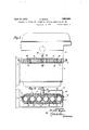
- F igure 1 of the accompanying drawings is a side elevation of an internal combustion engine showing the air cleaner applied thereto in 40 accordance with the present invention.
- Figure 2 isan end elevation of the engine with the air cleaner shown in transverse section on line 22, Figure 1.
- Figure ,3 is ahorizontal section on line 3 3, Figure 1.
- t f i v Referring to the drawings, the lower and unjacketed portions 1 of the engine cylinder barrels,- between the water-jacket 2 and the crankcase 3,, are enclosed by an encircling i sheet-metal casing 4 fitting closely'against the One of the objects of the lower part of the water-j acket andthe top of the crankcase respectively.
- a continuous chamber orspace 5 is thus produced between the casing 4 andthe cylinder barrels 1, and i this space is filledor loosely packed withhair, metal wool or other suitable air-filtering f terial 6 whichwill allow of the free, passage of air butwhich will intercept any dust, dirt or other solid material contained in the air.
- the casing 4 may be made in two separate vertical halves adapted to be applied to the cylinder barrels from opposite sides and to be permanently or d-etachably secured together, when in place, by means of opposed flanges 7,7, at the ends of the said halves,,these flanges being-secured together by bolts, rivets or other suitable means
- Theouter wallof the cleaner casing perforated at 8 tov permit of the entrance of air
- the engine induction which, after flowing through the porous packing 6 and being cleaned therebyand warmed by the heat of the cylinder barrels, is drawn by the engine induction through an outlet 9 in the casing and through a suitable pipe or passage 10 leading to the carburetter 11.
- the said outlet 9 maybe situatedat the middleof one side of the casing, and may be coveredby a wire gauze guard12 located withinthe cleaner chamber and suitably secured to the wallthereofp .1 s, '1
- the upper part of the engine crankcase 3 may be provided with holes 13 which communicate with the interior oftheair cleaner, so that gases or oil vapourcan'be drawnfrom the crankcase into the cleaner and thence through theengine, being consumed therein or being ejected through the exhaust system.
- Upstanding U-shaped guards 14 may be attached by their edges to the inside face of the wall of the casing 4 immediately over "the holes 13in the crankcase 3 to form vertical passages for the gas or vapour, said guards resting on the topof the crankcase and extending for a portion of the'height of the cleaner chamber, being open at the top.
- These guards orpassages 14 prevent the passageof excess oil from the crankcase into the cleaner and alsoprevent the entrance into the crankcase of any solid particles coll ected'by the cleaning medium. .10?
- the cleaner As the cleaner is made to embrace the un- 5 jacketed portion of the cylinder barrels and fits between the bottom of the water-jacket and the top of the crankcase, it can be designed so as to be contained within-or'fiush' With the general outline of the engine, thus providing a neat and compact arrangement.
- crank case engine cylind'ershaving a water l jacket spaced from the crank case by unjaclc an air cleaner surrounding the said unj acketed parts of the cylinders and having an outlet leading to the "carb'uretter, means for admitting air into the aincleaner, and an upstanding open topped passageeirtending from the interior of the crank case into the interior of the air cleaner 5/ i for a p'0r tion ofthe height of said cleaner.
- a water-jacket 1 and it crank an air cl e'aner' 'and warmer comprising a casing formed separately'from the engine and fitted secured aroundthe cylinde'r barrels, between said water-jacket and the crank c'hambentofor m a*c'ontiiiuous"c0m-' "saidengine cylinders, air cleaning material wlthln thecoinpartment, means for nserting "and removing" said air cleaning material, an
- an air cleaner “comprising a fc'asing rormed separately from the engine and fitltd' and secured' around the eylinder bar'reis between said water-j acket aridsa'id erankease toiform a continuous comp-armament: unding the said casing lying within the content 6f the upper virat'ei i'acketed part b fYt/he eI lglne', EtIlCllUWli 'fldhgs on thcasing dpposfed wthe' engi'ne (iYlifiderS, air cleaning material Within tI 'e coin'partmeia; an epening termed iii the 'casing and communicating winetheatmosphene;and a p pe leading fromthec'asingto the'air-ir'itake of the' e'iigine.
- an air cleaner comprising a two-part casing formed separately from the engine fitted around the cylinder barrels between" said water-jacket and said crank case, so as to be contained within the general outline of the engine, means for securing the two parts of the casing together so as to form a continuous chamber surrounding the engine cylinders, flanges on the two parts of the casing opposed to said engine cylinders, air cleaning material within the chamber, perforations formed in the casing, a, pipe leading from the casing to the air-intake of the engine, and a pipe leading from the crank case and communicating with the interior of the casing.
Landscapes
- Engineering & Computer Science (AREA)
- Chemical & Material Sciences (AREA)
- Combustion & Propulsion (AREA)
- Mechanical Engineering (AREA)
- General Engineering & Computer Science (AREA)
- Lubrication Details And Ventilation Of Internal Combustion Engines (AREA)
Description
0. BODEN April 12, 1932.
COMBINED ATR HEATER AND CLEANER FOR INTERNAL QbMBUSTION ENGINES INVENTOR OLIVER 80 EN ATTORNEYS April 12,1932. 0. BODEN 1,853,892
COMBINED AIR HEATER AND CLEANER FOR INTERNAL COMBUSTION ENGINES Filed Dec. 12, 1950 2 Sheets-Sheet 2 v INVENTOR BY N v ATTORNEYS Patented Apr. 12, 1932 OLIVER B'onEN, or BIRMINGl-lIAM, ENG-LAND COMBINED AIR nn'rnn AND CLEANER non-INTERNAL ooMBUs'rIoN ENGINES Application filed December 12, 1930, Serial No. 501,793,'and in Great Britain October 21, 1930.
This invention relates to air cleaners or scrubbers for use in connection with internal combustion engines for the purpose of inter cepting dust, .dirt or other solid particles contained in the air which passes into the cylinjder ,or cylinders.
present invention is to provide an improved 7 form of air cleaner by means of which the air passing to the engine is warmed before reach- I 10 ing the carburetter and which ensures the en: vgine cylinders being cooled by the passage of v the air through the cleaner. v i A further object, particularlyinthe case of automobile engines, is to utilizethe air cleaner for preventing gases andoil vapour from the v engine crankcase, from passing into the ve-v .hicle body.
Another object .is to provide an air cleaner device which is fitted to the engine so as not to extend beyond the general outline of the engine, thereby forming a neat, compact and iconvenientarrangement.
According to :the invention, the aircleaner V .comprises a perforated or. apertured casing surrounding the cylinder barrel or barrels and enclosing suitable air filtering or cleaning ma- 'terial, Thus, the air, in passing through the cleaner, is warmed by'the engine cylinders and cools the saidcylinders by the exchange 1 3001f heath The engine crankcase may be arrangedto'communicate by suitable apertures orpassages with the air cleaner,so, that gases and oilvapour from the crankcase may pass I into the cleaner and thence to the engine, be-
j 1 ing consumed therein or being ejected through the exhaust system.
F igure 1 of the accompanying drawings is a side elevation of an internal combustion engine showing the air cleaner applied thereto in 40 accordance with the present invention.
Figure 2 isan end elevation of the engine with the air cleaner shown in transverse section on line 22, Figure 1. I t
Figure ,3 is ahorizontal section on line 3 3, Figure 1. t f i v Referring to the drawings, the lower and unjacketed portions 1 of the engine cylinder barrels,- between the water-jacket 2 and the crankcase 3,, are enclosed by an encircling i sheet-metal casing 4 fitting closely'against the One of the objects of the lower part of the water-j acket andthe top of the crankcase respectively. A continuous chamber orspace 5 is thus produced between the casing 4 andthe cylinder barrels 1, and i this space is filledor loosely packed withhair, metal wool or other suitable air-filtering f terial 6 whichwill allow of the free, passage of air butwhich will intercept any dust, dirt or other solid material contained in the air.
The casing 4 may be made in two separate vertical halves adapted to be applied to the cylinder barrels from opposite sides and to be permanently or d-etachably secured together, when in place, by means of opposed flanges 7,7, at the ends of the said halves,,these flanges being-secured together by bolts, rivets or other suitable means Theouter wallof the cleaner casing perforated at 8 tov permit of the entrance of air,
which, after flowing through the porous packing 6 and being cleaned therebyand warmed by the heat of the cylinder barrels, is drawn by the engine induction through an outlet 9 in the casing and through a suitable pipe or passage 10 leading to the carburetter 11. The said outlet 9 maybe situatedat the middleof one side of the casing, and may be coveredby a wire gauze guard12 located withinthe cleaner chamber and suitably secured to the wallthereofp .1 s, '1 The upper part of the engine crankcase 3 may be provided with holes 13 which communicate with the interior oftheair cleaner, so that gases or oil vapourcan'be drawnfrom the crankcase into the cleaner and thence through theengine, being consumed therein or being ejected through the exhaust system. Upstanding U-shaped guards 14 may be attached by their edges to the inside face of the wall of the casing 4 immediately over "the holes 13in the crankcase 3 to form vertical passages for the gas or vapour, said guards resting on the topof the crankcase and extending for a portion of the'height of the cleaner chamber, being open at the top. These guards orpassages 14 prevent the passageof excess oil from the crankcase into the cleaner and alsoprevent the entrance into the crankcase of any solid particles coll ected'by the cleaning medium. .10?
" 20' etedparts of the cylinders,
d chamber,
" '55 partinent surrounding the lower portions of l {opening '55 to the air-intake of thecarburetter.
Alternative or additional passages may be formed between the crankcase and cleaner chamber by suitable external pipes.
As the cleaner is made to embrace the un- 5 jacketed portion of the cylinder barrels and fits between the bottom of the water-jacket and the top of the crankcase, it can be designed so as to be contained within-or'fiush' With the general outline of the engine, thus providing a neat and compact arrangement.
Instead of the whole of "one side of the" casing having perforations one or other number of holes or gaps may beprovided.
"Having, fully described my inventiom'what' I desire to claim and secure by Letters Pat- 1; In an internal combustion engine, a
crank case, engine cylind'ershaving a water l jacket spaced from the crank case by unjaclc an air cleaner surrounding the said unj acketed parts of the cylinders and having an outlet leading to the "carb'uretter, means for admitting air into the aincleaner, and an upstanding open topped passageeirtending from the interior of the crank case into the interior of the air cleaner 5/ i for a p'0r tion ofthe height of said cleaner.
2. In an internal combustionengine havf-ing' cylinders, a water-jacket 1 and it crank an air cl e'aner' 'and warmer comprising a casing formed separately'from the engine and fitted secured aroundthe cylinde'r barrels, between said water-jacket and the crank c'hambentofor m a*c'ontiiiuous"c0m-' "saidengine cylinders, air cleaning material wlthln thecoinpartment, means for nserting "and removing" said air cleaning material, an
-ing from the casing tothe air-intake of the 'carloiiretter. I V p i p i i 3. In an internal combustion enginahav ing 'cyli nders, "a water jacketf and a crank 5 chamber, a n air cleaner and warmer comprisfro1nthe engine anaffia'ea around the-cylin der barrels between saidwater-ja'cket and "the"cran'k chambenineans for securing the twoparts of the casing-together to form a continuouscoinpartinent surrounding" the engine'cylinclers, air cleaningmaterialwithin the compartment, an opening formed in the 'casingtand a pipe leading from the easing lf-An air cleaner and warmer for an in-' ternal combustion engine having-cylinders; a "water-jacket and a crank-case, 'con'iprising a casing adapted to extend around the lower portions of said engine'cylinders between said' water-jacket and saidcranlrcase, said i casing 'having' anelongated' opening to receiv'e'th'e cylinders and farmin asamma ous'eompartme'fit arpundthe latter, air clean ing material withinsaidconipartrnenfl'means engine-cylinders,
' general V *ing" cylinders, formed in thecasmg and conimunio eating with the'atmosphere, and a 'pipe lead-' tions of said engine cylinders between said water-jacket and said crank case, said casing having 'a' neloiigated opening to receive the cylinders, flanges at the upper and lower edges ofth casing opposed to the engine cylinders, means for-"securing-th'e two parts of the casing together to provide a continuous compartment surrounding said engine cylinders, 5 air cleaning "lfitttiiiil within the compartment, an 'ep'ening formed ih' the 'casing, and a pipe"leading'ffroin the easing to the air' intake of the engine, 7
6. In an" internal "combustionengine "having cylinders, a Wvater j aek'e andaeraak case,
an air cleaner "comprising a fc'asing rormed separately from the engine and fitltd' and secured' around the eylinder bar'reis between said water-j acket aridsa'id erankease toiform a continuous comp-armament: unding the said casing lying within the content 6f the upper virat'ei i'acketed part b fYt/he eI lglne', EtIlCllUWli 'fldhgs on thcasing dpposfed wthe' engi'ne (iYlifiderS, air cleaning material Within tI 'e coin'partmeia; an epening termed iii the 'casing and communicating winetheatmosphene;and a p pe leading fromthec'asingto the'air-ir'itake of the' e'iigine.
7. ,In an internal eembusttio enginehav- I water jakefi and a crank case, an air Chaney-tempting -a two-part casing] formed separately "from the fig ine and'fitted 'arol'liid the liylinder barrels between said water ja'cket'antl said male case so as w be contained withinthe general outline of -the engineg-"mean's fbir seeuring the p p r "two parts o'f the das'ing' togther ta form a "ing atwo parflcasing formed separately admin-nous chamber "siii r'dliiid'ing th'e iigine cylinders,- afl'ange atthe iip'prledge of each part bathe easing engaging saidicylinders and said water j acke't, at theTOWer edge o'feach-part ofi th'e casing-engaging said cylinders and said crankcase;'aiwaieanin material" within the t ehamb er, o'p enings formed in tlie casing "and 1 eb'mm fii'idating with theatmdsphere, and api'pleadirfgfrom the casing to the air 'intake be the eiigine 8} In anin'tern'al-combastioneiigihe having cylinders, a and a 'crank chamber, an aii clean ler coiiipiising.abasing formed separately from eaten-gins ,fitted and secured around the cylinderbarrels betweensaid water-j ticket and chamber't'o form continuous"compartment surroundin the lower portions ofi'fthe engine cylinders, airaaniagmaenar compartment, expelling "fol-med iirth casing and communicating with the atmosphere, a pipe leading from the casing to the air-inu take of the engine, and means for placing the compartment in communication with the interior of the crank case.
9. In an internal combustion enginehaving cylinders, a water-jacket and a crank case, an air cleaner comprising a two-part casing formed separately from the engine fitted around the cylinder barrels between" said water-jacket and said crank case, so as to be contained within the general outline of the engine, means for securing the two parts of the casing together so as to form a continuous chamber surrounding the engine cylinders, flanges on the two parts of the casing opposed to said engine cylinders, air cleaning material within the chamber, perforations formed in the casing, a, pipe leading from the casing to the air-intake of the engine, and a pipe leading from the crank case and communicating with the interior of the casing.
In testimony whereof I have afiixed my signature.
OLIVER BODEN.
Applications Claiming Priority (1)
| Application Number | Priority Date | Filing Date | Title |
|---|---|---|---|
| GB1853892X | 1930-10-21 |
Publications (1)
| Publication Number | Publication Date |
|---|---|
| US1853892A true US1853892A (en) | 1932-04-12 |
Family
ID=10892021
Family Applications (1)
| Application Number | Title | Priority Date | Filing Date |
|---|---|---|---|
| US501793A Expired - Lifetime US1853892A (en) | 1930-10-21 | 1930-12-12 | Combined air heater and cleaner for internal combustion engines |
Country Status (1)
| Country | Link |
|---|---|
| US (1) | US1853892A (en) |
Cited By (6)
| Publication number | Priority date | Publication date | Assignee | Title |
|---|---|---|---|---|
| US2534983A (en) * | 1947-01-17 | 1950-12-19 | Gerald F Mooney | Attachment for internalcombustion engines |
| US2944628A (en) * | 1956-10-02 | 1960-07-12 | Luwa Ltd | Air conditioning apparatus |
| EP0741242A1 (en) * | 1995-05-05 | 1996-11-06 | Société Anonyme dite: REGIE NATIONALE DES USINES RENAULT | Intake air conduit element for an internal combustion engine |
| US6267795B1 (en) * | 1999-07-09 | 2001-07-31 | John Givargis | Air cleaning system |
| US6613130B2 (en) | 1999-07-09 | 2003-09-02 | G.E.N. Industries Corp | Filtering system for removing combustion gases from an airflow |
| US7438027B1 (en) * | 1971-07-08 | 2008-10-21 | Hinderks Mitja V | Fluid transfer in reciprocating devices |
-
1930
- 1930-12-12 US US501793A patent/US1853892A/en not_active Expired - Lifetime
Cited By (7)
| Publication number | Priority date | Publication date | Assignee | Title |
|---|---|---|---|---|
| US2534983A (en) * | 1947-01-17 | 1950-12-19 | Gerald F Mooney | Attachment for internalcombustion engines |
| US2944628A (en) * | 1956-10-02 | 1960-07-12 | Luwa Ltd | Air conditioning apparatus |
| US7438027B1 (en) * | 1971-07-08 | 2008-10-21 | Hinderks Mitja V | Fluid transfer in reciprocating devices |
| EP0741242A1 (en) * | 1995-05-05 | 1996-11-06 | Société Anonyme dite: REGIE NATIONALE DES USINES RENAULT | Intake air conduit element for an internal combustion engine |
| FR2733799A1 (en) * | 1995-05-05 | 1996-11-08 | Renault | AIR INTAKE CIRCUIT MEMBER FOR INTERNAL COMBUSTION ENGINE |
| US6267795B1 (en) * | 1999-07-09 | 2001-07-31 | John Givargis | Air cleaning system |
| US6613130B2 (en) | 1999-07-09 | 2003-09-02 | G.E.N. Industries Corp | Filtering system for removing combustion gases from an airflow |
Similar Documents
| Publication | Publication Date | Title |
|---|---|---|
| US1853892A (en) | Combined air heater and cleaner for internal combustion engines | |
| US2797674A (en) | Crankcase ventilation system | |
| US3111120A (en) | Engine crankcase ventilation system | |
| US2518082A (en) | Auxiliary air admission device for internal-combustion engines | |
| US1654147A (en) | Crank-case ventilator | |
| US3450117A (en) | Internal combustion engine air filters | |
| JPH06330720A (en) | Positive crankcase ventilation of water cooling internal combustion engine | |
| US1362251A (en) | Fuel economizer, mixer, and separator for internal-combustion engines | |
| US1820795A (en) | Air cleaner | |
| US2763251A (en) | Induction means | |
| US1721525A (en) | mougey | |
| US1523524A (en) | Fuel condenser for intake manifolds of internal-combustion engines | |
| US1779921A (en) | Internal-combustion engine | |
| US1701490A (en) | Oil rectifier | |
| JPS6221965B2 (en) | ||
| US1637768A (en) | Manifold-heat retainer | |
| US1712939A (en) | Combined air cleaner, oil filler, and crank-case breather | |
| US1797978A (en) | Carburetor attachment for automobiles | |
| US1743023A (en) | Internal-combustion engine | |
| US1442258A (en) | doeeis | |
| US2477708A (en) | Gasoline conserving power increasing vaporizer | |
| US1463416A (en) | Air cleaning and heating attachment for internal-combustion engines | |
| US1766928A (en) | Motor preheater and cooler | |
| US2858820A (en) | Vaporizer for heavy and semi-heavy liquid fuels | |
| US1812860A (en) | Internal combustion engine |