US1853885A - Switch - Google Patents
Switch Download PDFInfo
- Publication number
- US1853885A US1853885A US450671A US45067130A US1853885A US 1853885 A US1853885 A US 1853885A US 450671 A US450671 A US 450671A US 45067130 A US45067130 A US 45067130A US 1853885 A US1853885 A US 1853885A
- Authority
- US
- United States
- Prior art keywords
- arc
- switch
- liquid
- pressure
- extinguishing liquid
- Prior art date
- Legal status (The legal status is an assumption and is not a legal conclusion. Google has not performed a legal analysis and makes no representation as to the accuracy of the status listed.)
- Expired - Lifetime
Links
- 239000007788 liquid Substances 0.000 description 36
- 239000012530 fluid Substances 0.000 description 13
- CURLTUGMZLYLDI-UHFFFAOYSA-N Carbon dioxide Chemical compound O=C=O CURLTUGMZLYLDI-UHFFFAOYSA-N 0.000 description 10
- 229910002092 carbon dioxide Inorganic materials 0.000 description 5
- 239000001569 carbon dioxide Substances 0.000 description 5
- 238000000926 separation method Methods 0.000 description 4
- 230000002159 abnormal effect Effects 0.000 description 3
- 239000004020 conductor Substances 0.000 description 3
- 238000004880 explosion Methods 0.000 description 3
- 230000008093 supporting effect Effects 0.000 description 3
- 238000004804 winding Methods 0.000 description 3
- 238000002485 combustion reaction Methods 0.000 description 2
- 238000009413 insulation Methods 0.000 description 2
- 239000012212 insulator Substances 0.000 description 2
- VZGDMQKNWNREIO-UHFFFAOYSA-N tetrachloromethane Chemical compound ClC(Cl)(Cl)Cl VZGDMQKNWNREIO-UHFFFAOYSA-N 0.000 description 2
- 238000009834 vaporization Methods 0.000 description 2
- 230000008016 vaporization Effects 0.000 description 2
- CDBYLPFSWZWCQE-UHFFFAOYSA-L Sodium Carbonate Chemical compound [Na+].[Na+].[O-]C([O-])=O CDBYLPFSWZWCQE-UHFFFAOYSA-L 0.000 description 1
- 238000009825 accumulation Methods 0.000 description 1
- 230000015572 biosynthetic process Effects 0.000 description 1
- 229950005499 carbon tetrachloride Drugs 0.000 description 1
- 230000006835 compression Effects 0.000 description 1
- 238000007906 compression Methods 0.000 description 1
- 238000010276 construction Methods 0.000 description 1
- 230000007797 corrosion Effects 0.000 description 1
- 238000005260 corrosion Methods 0.000 description 1
- 230000006866 deterioration Effects 0.000 description 1
- 230000005611 electricity Effects 0.000 description 1
- 239000002360 explosive Substances 0.000 description 1
- 238000002347 injection Methods 0.000 description 1
- 239000007924 injection Substances 0.000 description 1
- 239000011810 insulating material Substances 0.000 description 1
- 239000002184 metal Substances 0.000 description 1
- 239000000203 mixture Substances 0.000 description 1
- 230000001681 protective effect Effects 0.000 description 1
- 238000010791 quenching Methods 0.000 description 1
- 230000000171 quenching effect Effects 0.000 description 1
- 235000002020 sage Nutrition 0.000 description 1
- 239000000126 substance Substances 0.000 description 1
Images


Classifications
-
- H—ELECTRICITY
- H01—ELECTRIC ELEMENTS
- H01H—ELECTRIC SWITCHES; RELAYS; SELECTORS; EMERGENCY PROTECTIVE DEVICES
- H01H33/00—High-tension or heavy-current switches with arc-extinguishing or arc-preventing means
- H01H33/02—Details
- H01H33/53—Cases; Reservoirs, tanks, piping or valves, for arc-extinguishing fluid; Accessories therefor, e.g. safety arrangements, pressure relief devices
- H01H33/55—Oil reservoirs or tanks; Lowering means therefor
Definitions
- the physical separation of the electrical contacts, terminals or conducting parts, where the current is to be interrupted is a relatively simple matter in itself.
- the physical separation of the conducting parts does, not necessarily entail an interruption of the current flow as the current flow continues in the form of arc conduction, which may be of a greater or less extent depending upon such factors as voltage, speed of separation of the conductors, medium within which the circuit is interrupted, resistance and reactance of the circuit, frequency, and the like.
- breaking the continuity of the normal conducting path results in the formation of an arc of greater or less severity. Increased voltages increase the difficulties of interrupting the current flow.
- a more specific provision of the aforesaid invention is for injecting or delivering a jet of the arc extinguishing liquid upon the arc and contacts at the point of interruption, as the contacts separate.
- Air under pressure as a source of fluid pressure for injecting or delivering the arc extinguishing liquid has a number of marked disadvantages. Its combustion supporting property presents a potential danger.
- the interrupting device is operated when the quantity of arc extinguishing liquid is low so that the arc extinguishing liquid is all delivered or injected and the air follows through to the arc, or in any other manner reaches the are, an explosion may result. In any event, the arc will be increased instead of extinguished, with an accompanying continuation of the current flow. Furthermore, air causes corrosion and permits moisture accumulation which causes deterioration.
- the carbon dioxide gas merely follows and serves as an arc-extinguishing fluid of less effectiveness than the liquid, but highly advantageous in blanketing the oil or the vapors against explosion.
- Another object of the present invention is the provision of an improved expansion chamber for relieving the pressure when the interruption occurs in an enclosure or well and heavy arcing and excessive vaporization takes place.
- this chamber operates to increase the volume of the well, and in its more specific aspect, it is operated by the pressure created to increase the volume of the well simultaneously render vent means active and increase the action of said vent means as the volume of the well is increased.
- Still another object of the present inven tion is to provide for automatically interrupting the circuit upon a slight abnormal condition or a slight disturbance, relying upon the oil or other liquid bath normally surrounding the circuit terminals to extinguish the arc and for automatically interrupting the circuit and delivering the arc extinguishing liquid held in reserve to the point of interruption upon the occurrence of a heavier surge of current or a disturbance of greater severity.
- Figure 1 is a more or less diagrammatic vertical sectional view through a well known type of oil switch showing the application of the features of my invention thereto;
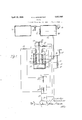
- Figure 2 is an enlarged front elevational view of the oil switch showing the expansion chamber in section;
- Figure 3 is a side elevational view of the switch showing the expansion chamber in elevation.
- Figure 4 is a detail horizontal section through the expansion chamber on line 44 of Figure 2.
- 5 designates a closed vessel or container provided with a cover 6 through which projects the main line conductors or high tension connections 7 and 8 terminating in stationar switch contact members or terminals 9 an 10.
- These contact members 9 and 10 may be of any desired form and need not be described in detail here.
- the conductors or connections 7 and 8 which are connected to said contact members 9 and 10 are led through the cover 6 by means of insulators 1212 which may be of any suitr able or preferred type, which support contact members 9 and 10 and said insulators are preferably sealed into the cover 6 so that a tight joint is maintained.
- a movable switch member 15 adapted for reciprocation into and out of contact with the stationary contact members 9 and 10 is mounted on a suitably insulated rod 16 which extends up through and is guided in the cover 6.
- a compression spring 18 between the upper end of rod 16 and a relatively fixed abutment tends to force the rod 16 downwardly and the switch member 15 carried thereby out of engagement with switch contact memhere 9 and 10.
- a solenoid 22 controls a pawl or catch 24 which is adapted to engage under a flange or shoulder 25 at the upper end of the rod 16 tohold the switch member 15 in engagement with the contact members 9 and 10 against the action of spring 18.
- a spring 26 normally tends to force the pawl 24 into engagement under the flange or shoulder 25 to maintain the switch closed.
- solenoid 22 Energization of solenoid 22 is controlled by a relay 28 actuated by a suitable current transformer 30 in the main line 7-8, the solenoid 22 being energized from the lines 32-32 when the relay 28 is closed by an overload or other disturbance or abnormal condition in the main line 7-8.
- a nozzle 35 having a flat Wide mouth is mounted in the wall of the container 5 adjacent each of the switch terminal members 9 and 10 substantially as more specifically shown in my Patent Number 1,712,174 to which I have already referred.
- These nozzles 35 are preferably of insulating material so as not to impair the insulation of the switch parts within the container.
- the container may also be lined with insulation, but this is not shown here.
- the closed container 5 holds a body of insulating liquid 42. Any suitable or preferred insulating liquid may be provided at this point. Oil, because of its advantages as a permanent bath, normally surrounding the circuit terminals, is preferable.
- Conduit means 45 is provided for delivering an arc extinguishing liquid 46 from a reserve tank or other suitable source 48.
- a valve 50 in the conduit 45 controls the delivery of the arc extinguishing liquid 46 through the nozzle 35.
- the valve 50 is controlled by a lever 52 and is normally held in its closed position by a spring 55. It is opened by the action of a solenoid 58 diagrammatically shown as a winding 60 having a core 62.
- Energization of the winding 60 is controlled by a relay controlled by a current transformer 30 in the main line 78, the winding 60 being energized from the line 32-32 when the relay 65 is closed by an overload or other disturbance or abnormal condition in line 7-8, thus opening the valve 50 and delivering arc extinguishing liquid through the nozzles 35 to the point of interruption.
- the liquid 46 is preferably carbon-tetrachloride or a liquid such as that disclosed in the United States Patent Number 1,319,907, granted October 28, 1919, to Nicholas J. Conrad and myself.
- a liquid such as that disclosed in the United States Patent Number 1,319,907, granted October 28, 1919, to Nicholas J. Conrad and myself.
- the invention is not limited to the use of a particular fluid at these points.
- extinguishing liquid 46 is delivered from a tank 74 to the top of the tank 48 through a conduit or pipe connection 73 therebetween.
- a pressure reducing valve 75 is provided in the conduit or pipe connection 73 between the tanks 74 and 48, so that the fluid pressure means may be maintained in tank 74, for example, at a pressure higher than that required for delivering the arc extinguishing liquid through the nozzle 35 to the point of current interruption when the switch is opened and supplied at the pressure desired for properly delivering the arc extinguishing liquid.
- the reducing valve may be dispensed with.
- the tank 48 is provided with a pressure gage and alevel indicator 72. Supply means may of course be provided for automatically maintaining a constant level of arc extinguishing liquid in tank 48 at substantially the point shown.
- the fluid pressure means is primarily a commercially available fluid that may be maintained at the desired pressure and is at the same time incapable of supporting combustion and will not affect or spoil any of the desired qualities of the are extinguishing liquid.
- the particular fluid which I have discovered to be valuable in this connection and which I at this time deem preferable, is carbon dioxide (CO If it reaches the point of circuit interruption, there is no danger of explosion, or of its increasing the are but to the contrary, proper interruption of the current flow and extinguishment of the arc is aided. I do not intend to be limited to this particular fluid, however, but in tend to embrace such other fluids as will fall within the range of equivalents.
- the expansion chamber for relieving the pressure when the interruption occurs in an enclosure or well as in the embodiment shown comprises a sleeve or open top tube 80 communicating at its lower end through a conduit 81 with the interior of the well or container 5 preferably at a point adjacent the top thereof.
- the conduit 81 comprises a relatively short vertical tube supporting the sleeve or tube 80.
- the conduit 81 has a horizontal portion which is threaded into a fitting 82 which is in turn riveted, bolted or otherwise secured to the wall of container 5 at the point of entrance of conduit 81 thereinto.
- a hollow piston 85 closed at its upper end and open at its lower end is slidably mounted in the tube 80.
- the piston 85 is of an external diameter which is less than the internal diameter of tube 80 thus providing an annular space between the tube and piston, the piston being positioned concentrically within tube 80 by four diametrically opposite spacing strips 86 arranged vertically between the tube and piston.
- the relay 28 is adjusted, as for example by adjustment of a spring, to close upon a slighter disturbance than necessary to close the relay 65, and thereby energize the solenoid 22 and release catch 24 to permit the spring 18 to open the switch.
- the relay 65 is adjusted to close upon a disturbance of greater severity and it will be apparent that upon the occurrence of such a disturbance, the relays 28 and 65 both close their circuits, one to open the switch and the other to simultaneously deliver are extinguishing liquid 46 through nozzle to the point of current interruption. In this manner the.
- the relays may of course be set to deliver arc extinguishing liquid whenever interruption occurs, and regardless of the severity of the disturbance.
- FIGS. 2 and 3 the switch is shown mounted, by means of a bracket member 90 formed integral with the cover 6, upon horizontal frame members 91 which are in turn secured to an upright frame member 92 extending upwardly from a base 93.
- Braces 94 are connected diagonally between base 93 and a lower horizontal frame member 95.
- An expansion chamber of the class de scribed comprising a cylinder, a hollow piston closed at its outer end and open at its inner end, slidably mounted in said cylinder, and spacing means separating the wall of the piston from the wall of the cylinder, said spacing means being separated to provide a passage therebetween.
- An expansion chamber of the class described comprising a cylinder, a piston slidably mounted therein, and spacing means separating the wall of the piston from the wall of the cylinder, said spacing means being separated from one another to provide a pas sage therebetween.
- a closed container comprising a cylinder in communication with the interior of the container, and a piston slidably mounted in said cylinder, there being a fluid passageway between the piston and the cylinder wall for permitting the relieving of pressure within the container past the plston.
Landscapes
- Circuit Breakers (AREA)
Description
April 1932- E. o. SCHWEITZER 1,853,885
SWITCH Original Filed Feb. 26, 1923 3 Sheets-Sheet l Aprll 12, 1932.
E. o. SCHWEITZER SWITCH Original Filed Feb. 25, 1925 3 Sheets-Sheet 2 April 1932- E. o. SCHWEITZER 1,853,885
SWITCH Original Filed Feb. 26, 1923 3 Sheets-Sheet 3 Patented Apr. 12, 1932 PATENT OFFICE EDMUND O. SCHWEITZER, OF CHICAGO, ILLINOIS SWITCH Original applicationfiled February 26, 1923, Serial No. 621,357, new Patent No. 1,761,091, dated June 3,
1930. Divided and this application filed May 8, 1930.
This application is a division of my pending application, Serial No. 621,357, filed February 26, 1923, now Patent 1,761,091 of June 3, 1930, and relates to switchesor current interrupting and arc extinguishing means.
In interrupting heavy currents of electricity either by a purely switching operation or automatically by means of protective apparatus the physical separation of the electrical contacts, terminals or conducting parts, where the current is to be interrupted, is a relatively simple matter in itself. However, the physical separation of the conducting parts does, not necessarily entail an interruption of the current flow as the current flow continues in the form of arc conduction, which may be of a greater or less extent depending upon such factors as voltage, speed of separation of the conductors, medium within which the circuit is interrupted, resistance and reactance of the circuit, frequency, and the like. Whether the condition of interrupting the current flow be caused by a purely switching operation or automatically by an over-load circuit breaking device, breaking the continuity of the normal conducting path results in the formation of an arc of greater or less severity. Increased voltages increase the difficulties of interrupting the current flow.
In my Patent #1,712,174 of May 9, 1929, issued on an application which was copending with my application Serial Number 621,357, of which this is a division, I provide means for maintaining the electrical contacts or con ducting parts in a bath of oil for insulating purposes and for delivering to the point of current interruption, upon separation of the contacts, a suitable arc extinguishing liquid which will quickly and eiiectively extinguish the arc and which will, when vaporized, give Serial No. 450,671.
ing liquid used, among which are the fact that it gives off a non-inflammable arc extin uishing vapor and its are extinguishing ability, especially in interrupting a heavy current or on a heavy overload, while the objections to the use of higher are extinguishing liquld as a bath for the contacts is overcome.
A more specific provision of the aforesaid invention is for injecting or delivering a jet of the arc extinguishing liquid upon the arc and contacts at the point of interruption, as the contacts separate. This necessitates means for injecting or delivering the are extinguishing liquid and where fluid pressure means is desirable, I find that a further practical problem is presented. Air under pressure as a source of fluid pressure for injecting or delivering the arc extinguishing liquid has a number of marked disadvantages. Its combustion supporting property presents a potential danger. If the interrupting device is operated when the quantity of arc extinguishing liquid is low so that the arc extinguishing liquid is all delivered or injected and the air follows through to the arc, or in any other manner reaches the are, an explosion may result. In any event, the arc will be increased instead of extinguished, with an accompanying continuation of the current flow. Furthermore, air causes corrosion and permits moisture accumulation which causes deterioration.
To secure a suitable speed of injection of the arc extinguishing liquid so that minimum damage may be done by the are, I provide a gas under pressure which by its expansion can force the liquid from the reservoir which contains it, through the nozzles and into the path of the arc. Compressed air will not serve. It would make matters worse by forming in conjunction with the oil vapor, an explosive combustible mixture. Air in the oil tank is about the worst thing that could be introduced. I employ a cylinder of liquefied carbon dioxide gas, such as may be secured on the open market, and permit the gas at a suitable pressure as may be controlled by a reducing valve, to press upon the surface of the arc-extinguishing liquid in the tank or reservoir containing it. I find that the carbon dioxide gas is peculiarly suitable because of its inert characteristics, both with respect to the liquid which it engages, and also with respect to the arc itself and the metal vapors and the metallic contact and switch parts with which it comes in contact. It is also cheap and plentiful in addition to its other desirable characteristics.
Now if the arc-extin uishing liquid should be all expended before the tank or reservoir is refilled, the carbon dioxide gas merely follows and serves as an arc-extinguishing fluid of less effectiveness than the liquid, but highly advantageous in blanketing the oil or the vapors against explosion.
Another object of the present invention is the provision of an improved expansion chamber for relieving the pressure when the interruption occurs in an enclosure or well and heavy arcing and excessive vaporization takes place. In its broader aspect, this chamber operates to increase the volume of the well, and in its more specific aspect, it is operated by the pressure created to increase the volume of the well simultaneously render vent means active and increase the action of said vent means as the volume of the well is increased.
Still another object of the present inven tion is to provide for automatically interrupting the circuit upon a slight abnormal condition or a slight disturbance, relying upon the oil or other liquid bath normally surrounding the circuit terminals to extinguish the arc and for automatically interrupting the circuit and delivering the arc extinguishing liquid held in reserve to the point of interruption upon the occurrence of a heavier surge of current or a disturbance of greater severity.
In order to apprise those skilled in the art with the operation and the manner of utilizing and practicing the invention and, where they enter into the invention, with the construction and substances for carrying out the several aspects of the invention, I shall now describe a particular embodiment in connec tion with the accompanying drawings which form a part of the present specification.
In the drawings Figure 1 is a more or less diagrammatic vertical sectional view through a well known type of oil switch showing the application of the features of my invention thereto;
Figure 2 is an enlarged front elevational view of the oil switch showing the expansion chamber in section;
Figure 3 is a side elevational view of the switch showing the expansion chamber in elevation; and
Figure 4 is a detail horizontal section through the expansion chamber on line 44 of Figure 2.
In the embodiment of the invention selected for illustration, 5 designates a closed vessel or container provided with a cover 6 through which projects the main line conductors or high tension connections 7 and 8 terminating in stationar switch contact members or terminals 9 an 10. These contact members 9 and 10 may be of any desired form and need not be described in detail here. The conductors or connections 7 and 8 which are connected to said contact members 9 and 10 are led through the cover 6 by means of insulators 1212 which may be of any suitr able or preferred type, which support contact members 9 and 10 and said insulators are preferably sealed into the cover 6 so that a tight joint is maintained.
A movable switch member 15 adapted for reciprocation into and out of contact with the stationary contact members 9 and 10 is mounted on a suitably insulated rod 16 which extends up through and is guided in the cover 6.
A compression spring 18 between the upper end of rod 16 and a relatively fixed abutment tends to force the rod 16 downwardly and the switch member 15 carried thereby out of engagement with switch contact memhere 9 and 10. A solenoid 22 controls a pawl or catch 24 which is adapted to engage under a flange or shoulder 25 at the upper end of the rod 16 tohold the switch member 15 in engagement with the contact members 9 and 10 against the action of spring 18. A spring 26 normally tends to force the pawl 24 into engagement under the flange or shoulder 25 to maintain the switch closed. Energization of solenoid 22 is controlled by a relay 28 actuated by a suitable current transformer 30 in the main line 7-8, the solenoid 22 being energized from the lines 32-32 when the relay 28 is closed by an overload or other disturbance or abnormal condition in the main line 7-8.
A nozzle 35 having a flat Wide mouth is mounted in the wall of the container 5 adjacent each of the switch terminal members 9 and 10 substantially as more specifically shown in my Patent Number 1,712,174 to which I have already referred. These nozzles 35 are preferably of insulating material so as not to impair the insulation of the switch parts within the container. The container may also be lined with insulation, but this is not shown here.
In the particular embodiment shown the closed container 5 holds a body of insulating liquid 42. Any suitable or preferred insulating liquid may be provided at this point. Oil, because of its advantages as a permanent bath, normally surrounding the circuit terminals, is preferable. Conduit means 45 is provided for delivering an arc extinguishing liquid 46 from a reserve tank or other suitable source 48. A valve 50 in the conduit 45 controls the delivery of the arc extinguishing liquid 46 through the nozzle 35. The valve 50 is controlled by a lever 52 and is normally held in its closed position by a spring 55. It is opened by the action of a solenoid 58 diagrammatically shown as a winding 60 having a core 62. Energization of the winding 60 is controlled by a relay controlled by a current transformer 30 in the main line 78, the winding 60 being energized from the line 32-32 when the relay 65 is closed by an overload or other disturbance or abnormal condition in line 7-8, thus opening the valve 50 and delivering arc extinguishing liquid through the nozzles 35 to the point of interruption.
The liquid 46 is preferably carbon-tetrachloride or a liquid such as that disclosed in the United States Patent Number 1,319,907, granted October 28, 1919, to Nicholas J. Conrad and myself. In this manner, the valuable arc and fire extinguishing properties of the arc extinguishing liquid held in reserve are secured without the disadvantages of nor-- mally surrounding the circuit terminals therewith. Of course, the invention is not limited to the use of a particular fluid at these points.
The fluid pressure means which I provide for delivering the arc. extinguishing liquid 46 is delivered from a tank 74 to the top of the tank 48 through a conduit or pipe connection 73 therebetween. A pressure reducing valve 75 is provided in the conduit or pipe connection 73 between the tanks 74 and 48, so that the fluid pressure means may be maintained in tank 74, for example, at a pressure higher than that required for delivering the arc extinguishing liquid through the nozzle 35 to the point of current interruption when the switch is opened and supplied at the pressure desired for properly delivering the arc extinguishing liquid. Of course, if the fluid pressure means is maintained at a pressure suitable for the desired delivery of the arc extinguishing liquid, the reducing valve may be dispensed with. A high pressure however permits a greater reserve in a smaller area, and that is desirable. In practice I have employed a cylinder of liquefied carbon dioxide such as is used at soda fountains. When a cylinder is substantially empty I substitute a fresh cylinder. Where a reducing valve is employed, it may of course be adjusted to give any desired delivery pressure upon the arc extinguishing liquid. The tank 48 is provided with a pressure gage and alevel indicator 72. Supply means may of course be provided for automatically maintaining a constant level of arc extinguishing liquid in tank 48 at substantially the point shown.
As already pointed out, the fluid pressure means is primarily a commercially available fluid that may be maintained at the desired pressure and is at the same time incapable of supporting combustion and will not affect or spoil any of the desired qualities of the are extinguishing liquid. The particular fluid which I have discovered to be valuable in this connection and which I at this time deem preferable, is carbon dioxide (CO If it reaches the point of circuit interruption, there is no danger of explosion, or of its increasing the are but to the contrary, proper interruption of the current flow and extinguishment of the arc is aided. I do not intend to be limited to this particular fluid, however, but in tend to embrace such other fluids as will fall within the range of equivalents.
The expansion chamber for relieving the pressure when the interruption occurs in an enclosure or well as in the embodiment shown, comprises a sleeve or open top tube 80 communicating at its lower end through a conduit 81 with the interior of the well or container 5 preferably at a point adjacent the top thereof. The conduit 81 comprises a relatively short vertical tube supporting the sleeve or tube 80. The conduit 81 has a horizontal portion which is threaded into a fitting 82 which is in turn riveted, bolted or otherwise secured to the wall of container 5 at the point of entrance of conduit 81 thereinto.
A hollow piston 85 closed at its upper end and open at its lower end is slidably mounted in the tube 80. The piston 85 is of an external diameter which is less than the internal diameter of tube 80 thus providing an annular space between the tube and piston, the piston being positioned concentrically within tube 80 by four diametrically opposite spacing strips 86 arranged vertically between the tube and piston. An inverted U-shaped strap 88, the free ends of which are secured to tube 80 as by rivets 89, limits the outward or upward movement of piston 85.
From the foregoing, it will now be apparent that when interruption occurs and pressure is created-dangerously high pressures result where heavy arcing and vaporization take place-the piston 85 is forced outwardly or upwardly through the tube or conduit 80 by such pressure. This results in a quick increase of the volume of the well and a quick relief of the pressure. At the same time vent passages are opened out between the strips 86 and the exterior of piston 85 and interior of tube 80. Upon resetting the switch, the piston 85 is forced down to the lower or inner end of its movement, thus closing the vent openings and returning the well or container to its normal volume. The vent means may of course be omitted and the expansion chamber employed alone, and the joint between the piston and cylinder of said chamber may be made tight by a close fit, or by providing a liquid or other suitable seal.
To automatically interrupt the circuit upon a relatively slight disturbance, for example, without delivering arc extinguishing liquid 46 to the point of interruption, the relay 28 is adjusted, as for example by adjustment of a spring, to close upon a slighter disturbance than necessary to close the relay 65, and thereby energize the solenoid 22 and release catch 24 to permit the spring 18 to open the switch. The relay 65 is adjusted to close upon a disturbance of greater severity and it will be apparent that upon the occurrence of such a disturbance, the relays 28 and 65 both close their circuits, one to open the switch and the other to simultaneously deliver are extinguishing liquid 46 through nozzle to the point of current interruption. In this manner the. desirable properties of the arc quenching liquid l2 are taken advantage of wherever possible, and the liquid 46 with its better fire and are extinguishing qualities is called into action only where necessary. If desired, the relays may of course be set to deliver arc extinguishing liquid whenever interruption occurs, and regardless of the severity of the disturbance.
In Figures 2 and 3 the switch is shown mounted, by means of a bracket member 90 formed integral with the cover 6, upon horizontal frame members 91 which are in turn secured to an upright frame member 92 extending upwardly from a base 93. Braces 94; are connected diagonally between base 93 and a lower horizontal frame member 95.
While I have herein shown and described a particular embodiment of my invention it is to be understood that this is merely illustrative, and the invention is not limited to the particular embodiment herein shown. What I consider new, and desire to secure by Letters Patent, is
1. An expansion chamber of the class de scribed, comprising a cylinder, a hollow piston closed at its outer end and open at its inner end, slidably mounted in said cylinder, and spacing means separating the wall of the piston from the wall of the cylinder, said spacing means being separated to provide a passage therebetween.
2. An expansion chamber of the class described, comprising a cylinder, a piston slidably mounted therein, and spacing means separating the wall of the piston from the wall of the cylinder, said spacing means being separated from one another to provide a pas sage therebetween.
3. In combination, a closed container, circuit interrupting means therein, and an expansion chamber comprising a cylinder in communication with the interior of the container, and a piston slidably mounted in said cylinder, there being a fluid passageway between the piston and the cylinder wall for permitting the relieving of pressure within the container past the plston.
In witness whereof, I hereunto subscribe my name this 3rd day of May, 1930.
EDMUND O. SCHWEITZER.
Priority Applications (1)
| Application Number | Priority Date | Filing Date | Title |
|---|---|---|---|
| US450671A US1853885A (en) | 1923-02-26 | 1930-05-08 | Switch |
Applications Claiming Priority (2)
| Application Number | Priority Date | Filing Date | Title |
|---|---|---|---|
| US62135723 US1761091A (en) | 1923-02-26 | 1923-02-26 | And arc-extinguishing means |
| US450671A US1853885A (en) | 1923-02-26 | 1930-05-08 | Switch |
Publications (1)
| Publication Number | Publication Date |
|---|---|
| US1853885A true US1853885A (en) | 1932-04-12 |
Family
ID=27036088
Family Applications (1)
| Application Number | Title | Priority Date | Filing Date |
|---|---|---|---|
| US450671A Expired - Lifetime US1853885A (en) | 1923-02-26 | 1930-05-08 | Switch |
Country Status (1)
| Country | Link |
|---|---|
| US (1) | US1853885A (en) |
-
1930
- 1930-05-08 US US450671A patent/US1853885A/en not_active Expired - Lifetime
Similar Documents
| Publication | Publication Date | Title |
|---|---|---|
| US4086461A (en) | High-voltage circuit-interrupters | |
| JP2001189118A (en) | Hybrid breaker | |
| CN101635233A (en) | Insulating enclosed type pagoda-shaped fuse | |
| US1853885A (en) | Switch | |
| US2292547A (en) | Apparatus for interrupting electric circuits | |
| US1761091A (en) | And arc-extinguishing means | |
| US2459612A (en) | Compressed gas circuit interrupter | |
| US2091424A (en) | Fuse | |
| US1918151A (en) | Electric circuit breaker | |
| US3588606A (en) | Electrical inductive apparatus | |
| US2353765A (en) | Fire extinguishing system with remote controlled selective multiway distribution | |
| US2240233A (en) | Gas blast circuit breaker | |
| US1712174A (en) | Oil switch | |
| US1551514A (en) | John d | |
| US10665399B2 (en) | Gas circuit breaker | |
| US4183005A (en) | Circuit interrupting device | |
| US2834856A (en) | Load break device | |
| US2134470A (en) | Method of and means for interrupting current flow | |
| US1564656A (en) | Liquid-feed system | |
| US3129276A (en) | Gas filled terminal bushing with protective check valve | |
| US2091423A (en) | Circuit interrupter | |
| US2019348A (en) | Electric circuit interrupter | |
| US1566756A (en) | Ments | |
| JP2012253896A (en) | Electric power gas insulation apparatus, and filling or exhausting method of insulation gas for the same | |
| US4241248A (en) | Circuit interrupting device |