US1853823A - Wall covering - Google Patents
Wall covering Download PDFInfo
- Publication number
- US1853823A US1853823A US510442A US51044231A US1853823A US 1853823 A US1853823 A US 1853823A US 510442 A US510442 A US 510442A US 51044231 A US51044231 A US 51044231A US 1853823 A US1853823 A US 1853823A
- Authority
- US
- United States
- Prior art keywords
- board
- blocks
- backing
- anchor
- wall
- Prior art date
- Legal status (The legal status is an assumption and is not a legal conclusion. Google has not performed a legal analysis and makes no representation as to the accuracy of the status listed.)
- Expired - Lifetime
Links
- 239000000463 material Substances 0.000 description 30
- 239000011449 brick Substances 0.000 description 17
- 238000004873 anchoring Methods 0.000 description 6
- 239000002184 metal Substances 0.000 description 6
- 239000004570 mortar (masonry) Substances 0.000 description 5
- BFPSDSIWYFKGBC-UHFFFAOYSA-N chlorotrianisene Chemical compound C1=CC(OC)=CC=C1C(Cl)=C(C=1C=CC(OC)=CC=1)C1=CC=C(OC)C=C1 BFPSDSIWYFKGBC-UHFFFAOYSA-N 0.000 description 2
- 230000000694 effects Effects 0.000 description 2
- 238000007789 sealing Methods 0.000 description 2
- 238000004088 simulation Methods 0.000 description 2
- 210000002105 tongue Anatomy 0.000 description 2
- 206010012239 Delusion Diseases 0.000 description 1
- 239000004568 cement Substances 0.000 description 1
- 230000008602 contraction Effects 0.000 description 1
- 231100000868 delusion Toxicity 0.000 description 1
- 238000004519 manufacturing process Methods 0.000 description 1
- 238000000034 method Methods 0.000 description 1
Images
Classifications
-
- E—FIXED CONSTRUCTIONS
- E04—BUILDING
- E04F—FINISHING WORK ON BUILDINGS, e.g. STAIRS, FLOORS
- E04F13/00—Coverings or linings, e.g. for walls or ceilings
- E04F13/07—Coverings or linings, e.g. for walls or ceilings composed of covering or lining elements; Sub-structures therefor; Fastening means therefor
- E04F13/08—Coverings or linings, e.g. for walls or ceilings composed of covering or lining elements; Sub-structures therefor; Fastening means therefor composed of a plurality of similar covering or lining elements
- E04F13/14—Coverings or linings, e.g. for walls or ceilings composed of covering or lining elements; Sub-structures therefor; Fastening means therefor composed of a plurality of similar covering or lining elements stone or stone-like materials, e.g. ceramics concrete; of glass or with an outer layer of stone or stone-like materials or glass
- E04F13/147—Coverings or linings, e.g. for walls or ceilings composed of covering or lining elements; Sub-structures therefor; Fastening means therefor composed of a plurality of similar covering or lining elements stone or stone-like materials, e.g. ceramics concrete; of glass or with an outer layer of stone or stone-like materials or glass with an outer layer imitating natural stone, brick work or the like
Definitions
- My present invention relates to the art of wall covering wherein a wall, usually an exterior wall of a wooden building, is to be pro'- vided wit-h a surface giving the appearance of being formed of brick or the like.
- blocks intended to represent bricks and the like have been cemented or otherwise secured by surface attachment to sheets of backing material, such as composition boards and the boards have then been nailed to the wall.
- the blocks In such cases to properly carry out the delusion the blocks must be of a material of different charactei ⁇ than that of the backing and diiculty is ex erienced in maintaining a permanent bon or union between the blocks and the backing owing largely to the different coefficients of expansion and contraction of the two materials, and therefore in time the blocks tend to become loosened and in some cases detached from the backing.
- simulating bricks or the like which may be readily attached to the building; which will resent a close resemblance to a brick or similgr wall, and which will remain permanently in place and indefinitely retain the desired ap arance.
- a new and improved wall covering comprising -a composltion board backing preferably of material similar to cellotex which is a com osition formed .of came with bloc s formed of plastic material, such as cement, which are cast in place on the backing and with metallic anchors secured to the backing and having enlarged 'or angular ortions which are embedded in the materla of the blocks when such material is cast.
- the anchors extend -forwardly through openings in the bacln'ng board and have extended rear ends to prevent their being drawn forwardly through the backing.
- anchors sheet metal members havin twin projecting 'portions or flanges whic extend forwardly through ad- ]acent elongated openings in the backing board, and which have a connecting bridge or web ortion which lits against the rear face of t e backing between said o enings.
- One or more anchor members may be provided for each block and an anchor member may be of suflicient length to bridge a plurallty of blocks with plain sections without forwardly extending ortions corresponding to the 'spaces or val eys between adjacent blocks.
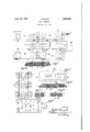
- Fig. 2 is a broken longitudinal section of the same taken along the line 2--2 in Fi 1.
- Fig. 3 is a plan view of my preferred orm of anchor member.
- Fig. 4 is a face view on reduced scale of ,the backing board.
- Fig. 5 is a broken plan view showing an anchor member individual to a sin le block.
- Fi 6 is a longitudinal section ta en along the lme 6--6 in Fig. 5.
- Figs. 7 and 8 are broken longitudinal sec- En i lllhese are indicated generally by the reference numeral 2, and are shown as arranged in three horizontally disposed rows of two blocks each, the top row comprising the 5 blocks 2a and 2b, the intermediate row comprising the blocks 2c and 2d, and the bottom drow comprising the blocks 2e and 2f. Separating the blocks and also running along certain of the perimetral edges of the units are the valleys 3 which are exposed portions of the backing board 1.
- rlhe blocks of adjacent rows are in staggered relation so as to brealr joints and also to permit the ends of adjacent units to interlock to form a continuous surface when the units are nailed or otherwise secured to'the building wall.
- rJlhe blocks are anchored to the backing board by means of metallic anchoring members attached to the board and having their outer ends embedded in the material of the blocks when the same is cast in plastic condi-l ⁇ tion.
- anchoring members eX- tend forwardly through openings in the backing board and have enlarged rear ends to prevent them from being drawn forwardly through the board.
- the figures now under discussion l show the board provided with pairs of parallel elongated openings or slot d disposed vertically on the board. At the center of the board a series of three pairs of said slots are arranged in vertical array, the members of the upper and lower pairs being on either side of the valley 3 which intervenes between the blocks of the row, while'the centenpair of slots are covered by the block 2c when the block is cast.
- a metallic anchor member which may be formed of a strip of sheet metal, preferably galvanized, t prevent rusting, and having its edges formed with bent tongues 6 which are inserted forwardly 45 through the slots 4 to protrude at the front of the board and the protruding portions of said slots are slit to form fingers 7 which are bent in opposite direction so that they are substantially parallel with the front face of the board 1 but spaced outwardly therefrom as best shown in Figs. 2 and 3.
- the central ortion of the anchor 5 bears against the hack face of the backing board, forming a bridge or web which prevents the anchor being drawn forwardly through the openings in the backing board.
- the plastic materialof which the blocks are formed is cast against the front face of the backing board o with the lingers 7 embedded therein, and thus vidual to the blocks 2a and 2e respectively,
- anchors being only lof suiicient length asesaeae to anchor a single block to the backing board.
- Similar short anchors 5a are used to anchor the outer ends of the blocks 2h and 2f to the backing board.
- FIG. 7 l show the use of another form of anchor comprising a pin 8 having an enlarged head 9, the pin being inserted forwardly through a hole 10 in the backing boardy 1 and having an enlarged cap or washer 11 fixed on its outer end as by riveting, which cap is embedded in the material of the block 2.
- F ig. 8 I show a bolt 12 having an enlarged head 13 used in asimilar manner, the nut 14 being screwed on the head of the bolt and being embedded in the material of the block 2.
- the valleys 3 are pointed with suitable mortar, thus producing an effect in very close simulation to a brick or like wall and also sealing the edges of the blocks at the joints between the edges of the blocks and the backing 'board against the entrance of moisture.
- the joints between the units are simi- Ala-rly pointed and sealed with mortar.
- my improved wall covering forms a very satisfactory and advantageous material for covering the walls of buildings in simulation of a wall formed of brick or other laid units.
- the blocks may be made of suitable plastic material and colored to the desired tints. The material is readily put up and will maintain its place. The blocks will not become accidentally loosened or detached and the use of bricklayers mortar for pointing the valleys and the joints greatly heightens the resemblance to the wall of brick or other laid units.
- a wall covering for simulating bricks and other laid building units comprising a backing board of composition, blocks cast of plastic material onto the face of the board, and metallic anchor members secured to the board and protruding forwardly therefrom and embedded in the material of the blocks.
- a wall covering for simulating bricks and other laid building units comprising a backing board of composition, blocks cast of plastic material onto the face of the board, and metallic anchor members secured to the boardand protruding forwardly therefrom and embedded in the material of the blocks,
- said anchor member having outer ends angular to'their body portions to assist the grip of the material of the blocks thereon.
- a wall covering for simulating bricks and other laid building units comprising a aeeaeae 'w the anchors being embedded in said material.
- a wall covering for simulating bricks and other laid building units comprising a backing 'board of composition having apertures formed therethrough, metallicanchor members inserted throughsaid apertures and having extended inner ends to prevent them frombeing drawn forwardly through the board, the outer ends of the anchor members being angular to their bodies, and blocks cast of materialwhile plastic onto the front face of the board, the outer ends of the anchor members being embedded in the material or the blocks.
- a wall covering for simulating bricks and other laid building units comprising a backing board of composition having a pair of parallel elongated apertures cut therethrough, a sheet metal anchoring member having'edge flanges protruding forwardlyv through said apertures while its central portion forms a bridge 'which bears against the rear face of the board, and said Hanges being bent parallel with the front face of the board, and a block cast of material while plastic onto the front face of the board, the protruding ianges being embedded in the material of the blocks.
- a wall covering for simulating bricks and other laid building units comprising a backing board of composition having a pair or parallel elongated apertures out therethroughVa sheet metal anchoring member having edge flanges protruding forwardly lill through said apertures while its central portion forms a bridge which bears against the rear tace of the board, and said anges being cut to form ngers which are bent in alternate vdirections parallel with the front faceot the board, and a block of material cast while plastic onto the front tace of the board,
- a wall covering for simulating briclrs and other laidbuilding units comprising a backing board of composition having a pair of .parallel elongated apertures cut therethrough, a sheet metal anchoringjmember hav. ing edge anges protrudingv forwardly through said apertures while its central portion forms a bridge which bears against the rear face oi the board, and said Hanges ⁇ being bent parallel with the front face of the board, and a plurality of blocks cast of material while plastic onto the front face el said board,
- a wall covering for simulating bricks and other laid building units comprising a backing board or composition, metallic anchoring members attached to said board Vand extending forwardly therefrom, blocks cast of material while plastic onto said board with valleys intervening between said blocks, the
- protruding portions of the anchoring members being embeddedfin the material of said blocks, and mortar pointing said valleys and sealing the Joints between the blocks and the backing board.
- a wall covering for simulating bricks and other laid building units comprising a e..
- ybacking board of composition said board ing provided with apertures therethrough, metallic anchor members extending forwardly through said apertures and having their rear ends extended to prevent them being drawn forwardly through said apertures, blocks cast o material while plastic onto the face ot the board with valleys intervening between adjacent blocks, and a pointin of mortar for said valleys to seal the joints between the blocks and the board,
Landscapes
- Engineering & Computer Science (AREA)
- Architecture (AREA)
- Chemical & Material Sciences (AREA)
- Ceramic Engineering (AREA)
- Civil Engineering (AREA)
- Structural Engineering (AREA)
- Finishing Walls (AREA)
Description
April 12,
1932. J. KRAUSS WALL COYERING Filed Jan. 22, 193i Fill lNvENToR Patented Apr. 12, 1932 UNMED 'STATES PATEr oFFlca J' OSEPH KBAUSS, 0F PITTSBURGH, QENNSYLVANIA, ASSIGNOR, BY DIRECT AND MESNE ASSIGNMENTS, T NEW BRICK CORPORATION, 01|?V PITTSBUBGE, PENNSYLVANIA, A
l WALL COVEBING' Application led January 22, 1931. Serial No. 510,442. I
My present invention relates to the art of wall covering wherein a wall, usually an exterior wall of a wooden building, is to be pro'- vided wit-h a surface giving the appearance of being formed of brick or the like.
Frequently for this purpose metal sheets colored and marked off to represent bricks and the like are nailed to the wooden backing, but the artificiality of such a surface is usua l quite apparent and the general effect is clieap and tawdry.
Again blocks intended to represent bricks and the like have been cemented or otherwise secured by surface attachment to sheets of backing material, such as composition boards and the boards have then been nailed to the wall. In such cases to properly carry out the delusion the blocks must be of a material of different charactei` than that of the backing and diiculty is ex erienced in maintaining a permanent bon or union between the blocks and the backing owing largely to the different coefficients of expansion and contraction of the two materials, and therefore in time the blocks tend to become loosened and in some cases detached from the backing.
One of the objects which I have in view is the provision of an inexpensive wall cover.
ing simulating bricks or the like which may be readily attached to the building; which will resent a close resemblance to a brick or similgr wall, and which will remain permanently in place and indefinitely retain the desired ap arance.
For t purpose I have invented a new and improved wall covering comprising -a composltion board backing preferably of material similar to cellotex which is a com osition formed .of suger cane with bloc s formed of plastic material, such as cement, which are cast in place on the backing and with metallic anchors secured to the backing and having enlarged 'or angular ortions which are embedded in the materla of the blocks when such material is cast.
In the preferrred embodiment'of my invention the anchors extend -forwardly through openings in the bacln'ng board and have extended rear ends to prevent their being drawn forwardly through the backing.`
I prefer to use as anchors sheet metal members havin twin projecting 'portions or flanges whic extend forwardly through ad- ]acent elongated openings in the backing board, and which have a connecting bridge or web ortion which lits against the rear face of t e backing between said o enings.
The ortions of the anchor mem ers which protru e forwardl from the backing board are bent to provi e better anchorage in the plastic material of the blocks, and I prefer to slit such portions of the anchor members to form tongues which are bent alternatel in either direction substantially parallel withI the backing board. A
One or more anchor members may be provided for each block and an anchor member may be of suflicient length to bridge a plurallty of blocks with plain sections without forwardly extending ortions corresponding to the 'spaces or val eys between adjacent blocks.
I have also invented a new and improved process of manufacturing such wall covering. In theaccom anying drawin s wherein I have illustrate a practical em odiment of the principles of my invention, Fig. l .is a face view of a section of my improved wall coverlng.
Fig. 2 is a broken longitudinal section of the same taken along the line 2--2 in Fi 1. Fig. 3 is a plan view of my preferred orm of anchor member.
Fig. 4 is a face view on reduced scale of ,the backing board.
Fig. 5 is a broken plan view showing an anchor member individual to a sin le block. Fi 6 is a longitudinal section ta en along the lme 6--6 in Fig. 5.
' Figs. 7 and 8 are broken longitudinal sec- En i lllhese are indicated generally by the reference numeral 2, and are shown as arranged in three horizontally disposed rows of two blocks each, the top row comprising the 5 blocks 2a and 2b, the intermediate row comprising the blocks 2c and 2d, and the bottom drow comprising the blocks 2e and 2f. Separating the blocks and also running along certain of the perimetral edges of the units are the valleys 3 which are exposed portions of the backing board 1.
rlhe blocks of adjacent rows are in staggered relation so as to brealr joints and also to permit the ends of adjacent units to interlock to form a continuous surface when the units are nailed or otherwise secured to'the building wall.
rJlhe blocks are anchored to the backing board by means of metallic anchoring members attached to the board and having their outer ends embedded in the material of the blocks when the same is cast in plastic condi-l` tion.
Preferably these anchoring members eX- tend forwardly through openings in the backing board and have enlarged rear ends to prevent them from being drawn forwardly through the board.
ln the figures now under discussion l show the board provided with pairs of parallel elongated openings or slot d disposed vertically on the board. At the center of the board a series of three pairs of said slots are arranged in vertical array, the members of the upper and lower pairs being on either side of the valley 3 which intervenes between the blocks of the row, while'the centenpair of slots are covered by the block 2c when the block is cast.
5 represents a metallic anchor member which may be formed of a strip of sheet metal, preferably galvanized, t prevent rusting, and having its edges formed with bent tongues 6 which are inserted forwardly 45 through the slots 4 to protrude at the front of the board and the protruding portions of said slots are slit to form fingers 7 which are bent in opposite direction so that they are substantially parallel with the front face of the board 1 but spaced outwardly therefrom as best shown in Figs. 2 and 3. The central ortion of the anchor 5 bears against the hack face of the backing board, forming a bridge or web which prevents the anchor being drawn forwardly through the openings in the backing board. The plastic materialof which the blocks are formed is cast against the front face of the backing board o with the lingers 7 embedded therein, and thus vidual to the blocks 2a and 2e respectively,
such anchors being only lof suiicient length asesaeae to anchor a single block to the backing board. Similar short anchors 5a are used to anchor the outer ends of the blocks 2h and 2f to the backing board.
ln the case of the block 2d also shown in Figs. 5 and 6 a single anchor 5b of greater width is employed to anchor the block to the backing board. y
ln Fig. 7 l show the use of another form of anchor comprising a pin 8 having an enlarged head 9, the pin being inserted forwardly through a hole 10 in the backing boardy 1 and having an enlarged cap or washer 11 fixed on its outer end as by riveting, which cap is embedded in the material of the block 2. In F ig. 8 I show a bolt 12 having an enlarged head 13 used in asimilar manner, the nut 14 being screwed on the head of the bolt and being embedded in the material of the block 2. f
After the blocks have been cast on the board and have set and hardened and have been properly cured the valleys 3 are pointed with suitable mortar, thus producing an effect in very close simulation to a brick or like wall and also sealing the edges of the blocks at the joints between the edges of the blocks and the backing 'board against the entrance of moisture. When the units are in interlocked relation the joints between the units are simi- Ala-rly pointed and sealed with mortar. j
It is apparent from the foregoing descrip' tion that my improved wall covering forms a very satisfactory and advantageous material for covering the walls of buildings in simulation of a wall formed of brick or other laid units. The blocks may be made of suitable plastic material and colored to the desired tints. The material is readily put up and will maintain its place. The blocks will not become accidentally loosened or detached and the use of bricklayers mortar for pointing the valleys and the joints greatly heightens the resemblance to the wall of brick or other laid units.
What I claim is 1. A wall covering for simulating bricks and other laid building units, comprising a backing board of composition, blocks cast of plastic material onto the face of the board, and metallic anchor members secured to the board and protruding forwardly therefrom and embedded in the material of the blocks.
2. A wall covering for simulating bricks and other laid building units, comprising a backing board of composition, blocks cast of plastic material onto the face of the board, and metallic anchor members secured to the boardand protruding forwardly therefrom and embedded in the material of the blocks,
K said anchor member having outer ends angular to'their body portions to assist the grip of the material of the blocks thereon.
3. A wall covering for simulating bricks and other laid building units, comprising a aeeaeae 'w the anchors being embedded in said material.
4c. A wall covering for simulating bricks and other laid building units, comprising a backing 'board of composition having apertures formed therethrough, metallicanchor members inserted throughsaid apertures and having extended inner ends to prevent them frombeing drawn forwardly through the board, the outer ends of the anchor members being angular to their bodies, and blocks cast of materialwhile plastic onto the front face of the board, the outer ends of the anchor members being embedded in the material or the blocks.
5. A wall covering for simulating bricks and other laid building units, comprising a backing board of composition having a pair of parallel elongated apertures cut therethrough, a sheet metal anchoring member having'edge flanges protruding forwardlyv through said apertures while its central portion forms a bridge 'which bears against the rear face of the board, and said Hanges being bent parallel with the front face of the board, and a block cast of material while plastic onto the front face of the board, the protruding ianges being embedded in the material of the blocks. p
5. A wall covering for simulating bricks and other laid building units comprising a backing board of composition having a pair or parallel elongated apertures out therethroughVa sheet metal anchoring member having edge flanges protruding forwardly lill through said apertures while its central portion forms a bridge which bears against the rear tace of the board, and said anges being cut to form ngers which are bent in alternate vdirections parallel with the front faceot the board, and a block of material cast while plastic onto the front tace of the board,
said lingers being embedded in the material oi the blocks.
7. A wall covering for simulating briclrs and other laidbuilding units comprising a backing board of composition having a pair of .parallel elongated apertures cut therethrough, a sheet metal anchoringjmember hav. ing edge anges protrudingv forwardly through said apertures while its central portion forms a bridge which bears against the rear face oi the board, and said Hanges `being bent parallel with the front face of the board, and a plurality of blocks cast of material while plastic onto the front face el said board,
'-of material while plastic. onto the front face of the board, said fingers being embedded in the material of said blocks.
9. A wall covering for simulating bricks and other laid building units, comprising a backing board or composition, metallic anchoring members attached to said board Vand extending forwardly therefrom, blocks cast of material while plastic onto said board with valleys intervening between said blocks, the
protruding portions of the anchoring members being embeddedfin the material of said blocks, and mortar pointing said valleys and sealing the Joints between the blocks and the backing board.
10, A wall covering for simulating bricks and other laid building units, comprising a e..
ybacking board of composition, said board ing provided with apertures therethrough, metallic anchor members extending forwardly through said apertures and having their rear ends extended to prevent them being drawn forwardly through said apertures, blocks cast o material while plastic onto the face ot the board with valleys intervening between adjacent blocks, and a pointin of mortar for said valleys to seal the joints between the blocks and the board,
' Signed at Pittsburgh, Pa., this 21st day of January, 1931..
' s JOSEPH mAUSS,
Priority Applications (1)
| Application Number | Priority Date | Filing Date | Title |
|---|---|---|---|
| US510442A US1853823A (en) | 1931-01-22 | 1931-01-22 | Wall covering |
Applications Claiming Priority (1)
| Application Number | Priority Date | Filing Date | Title |
|---|---|---|---|
| US510442A US1853823A (en) | 1931-01-22 | 1931-01-22 | Wall covering |
Publications (1)
| Publication Number | Publication Date |
|---|---|
| US1853823A true US1853823A (en) | 1932-04-12 |
Family
ID=24030749
Family Applications (1)
| Application Number | Title | Priority Date | Filing Date |
|---|---|---|---|
| US510442A Expired - Lifetime US1853823A (en) | 1931-01-22 | 1931-01-22 | Wall covering |
Country Status (1)
| Country | Link |
|---|---|
| US (1) | US1853823A (en) |
Cited By (1)
| Publication number | Priority date | Publication date | Assignee | Title |
|---|---|---|---|---|
| USD905281S1 (en) * | 2018-10-16 | 2020-12-15 | Tim Sarkkinen | Garden bed block |
-
1931
- 1931-01-22 US US510442A patent/US1853823A/en not_active Expired - Lifetime
Cited By (1)
| Publication number | Priority date | Publication date | Assignee | Title |
|---|---|---|---|---|
| USD905281S1 (en) * | 2018-10-16 | 2020-12-15 | Tim Sarkkinen | Garden bed block |
Similar Documents
| Publication | Publication Date | Title |
|---|---|---|
| US2196847A (en) | Covering element | |
| US1861359A (en) | Metal lath for brick veneers | |
| US1946646A (en) | Floor | |
| US1915964A (en) | Siding strip | |
| US2114450A (en) | Siding panel for buildings | |
| US1930024A (en) | Cement lath | |
| US1447567A (en) | Roof and roof covering | |
| US1378735A (en) | Building-block | |
| US2221475A (en) | Siding unit | |
| US1853822A (en) | Wall covering | |
| US1891530A (en) | Strip for terrazzo and similar floors | |
| US1853823A (en) | Wall covering | |
| US2248723A (en) | Strip for roofing | |
| US2293331A (en) | Wall facing | |
| US1975769A (en) | Anchor for brick, tile, and the like | |
| US2094688A (en) | Covering for surfaces exposed to the weather | |
| US2013391A (en) | Shingle strip | |
| US1911014A (en) | Siding shingles | |
| US2162886A (en) | Surface covering | |
| US2270808A (en) | Building unit | |
| US1688405A (en) | Wall-veneering material | |
| US2218791A (en) | Flexible siding material | |
| US2069444A (en) | Shingle | |
| US2519950A (en) | Siding | |
| US1505272A (en) | Reenforced-rubber-composition strip |