US1853793A - Furniture joint - Google Patents
Furniture joint Download PDFInfo
- Publication number
- US1853793A US1853793A US197121A US19712127A US1853793A US 1853793 A US1853793 A US 1853793A US 197121 A US197121 A US 197121A US 19712127 A US19712127 A US 19712127A US 1853793 A US1853793 A US 1853793A
- Authority
- US
- United States
- Prior art keywords
- corner
- furniture
- walls
- edges
- indicated
- Prior art date
- Legal status (The legal status is an assumption and is not a legal conclusion. Google has not performed a legal analysis and makes no representation as to the accuracy of the status listed.)
- Expired - Lifetime
Links
- 238000000034 method Methods 0.000 description 3
- 238000004519 manufacturing process Methods 0.000 description 2
- 238000005452 bending Methods 0.000 description 1
- 230000015572 biosynthetic process Effects 0.000 description 1
- 238000003801 milling Methods 0.000 description 1
- 238000000465 moulding Methods 0.000 description 1
- 238000005498 polishing Methods 0.000 description 1
- 239000007787 solid Substances 0.000 description 1
Images
Classifications
-
- F—MECHANICAL ENGINEERING; LIGHTING; HEATING; WEAPONS; BLASTING
- F16—ENGINEERING ELEMENTS AND UNITS; GENERAL MEASURES FOR PRODUCING AND MAINTAINING EFFECTIVE FUNCTIONING OF MACHINES OR INSTALLATIONS; THERMAL INSULATION IN GENERAL
- F16B—DEVICES FOR FASTENING OR SECURING CONSTRUCTIONAL ELEMENTS OR MACHINE PARTS TOGETHER, e.g. NAILS, BOLTS, CIRCLIPS, CLAMPS, CLIPS OR WEDGES; JOINTS OR JOINTING
- F16B12/00—Jointing of furniture or the like, e.g. hidden from exterior
- F16B12/44—Leg joints; Corner joints
- F16B12/46—Non-metal corner connections
-
- Y—GENERAL TAGGING OF NEW TECHNOLOGICAL DEVELOPMENTS; GENERAL TAGGING OF CROSS-SECTIONAL TECHNOLOGIES SPANNING OVER SEVERAL SECTIONS OF THE IPC; TECHNICAL SUBJECTS COVERED BY FORMER USPC CROSS-REFERENCE ART COLLECTIONS [XRACs] AND DIGESTS
- Y10—TECHNICAL SUBJECTS COVERED BY FORMER USPC
- Y10T—TECHNICAL SUBJECTS COVERED BY FORMER US CLASSIFICATION
- Y10T403/00—Joints and connections
- Y10T403/47—Molded joint
Definitions
- Zhmentor G. will/eel (Ittorneg April 12, 1932.. c. WC'JLLMER I FURNITURE JOINT- Filed June 7. 1927 2 Sheets-Sheet '2 Iftomeg Patented Apr. 12, 1932 r UNITED STATES CHRISTIAN woLLMER, OEI-IV'AIVIIBYURG, GERMANY FURNITURE zfofn'r Q Application filed June 7, iaatilfsegr ialf tb q 197,121;
- This invention is directed to a method of producing furniture of the type wherein the casings and corner connectionsare swelled or curved more than once.
- furniture of this type has necessitated more or less direct hand Q carving or molding, with the result that the product is unnecessarily heavyand comparatively expensive to produce.
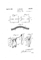
- Figure 3 is a sectional View showing the uniting of the single veneer surface to a veneer wall by pressure.
- Figure 4 is a broken perspective illustrating two casing walls provided with the corner connections.
- Figure 5 is a perspective View showing the corner connections united to secure the casing and walls in proper relation.
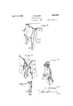
- Figure 6 is a broken perspective showing an end portion of a completed article of furniture constructed in accordance with the present invention.
- Figure 7 is a perspective View showing a corner connection formed for the reception of an independent carved corner finish element.
- Figure 8 is a perspective view from the inner side of a corner connection finish element.
- Figure 9 is a broken elevation showing a completed corner connection with attached finish element.
- a plain form 1 of approximate desired area is cut away on the edges to provide the wedge-shaped cuts 1", thereby permitting the form 1 when molded under pressure to assume the desired cur vature through the meeting of the edges of thecuts without lapping, such meeting-edges being indicated at 1 in Figure 2;
- a number ofjthe-veneer forms as illustrated in' - Figure 5 2 nterconnected bys'ultablel-bindingor adhea sive, as at 5',” are-subjected to pressure between matrices 3 and whichmaybe'solid castlngs produced from a plastlc mold correspondmg to the desired form of the wall.
- corner pieces are then secured together along the cut surfaces 12, providing the inner 5 right angularly related square edges 13 with the relatively outer surfaces of the corner connections or planks 10 merging into the curvature of the Walls, as will be plain from the indicated points 9 in Figure 4:.
- the corner 10 connection as thus completed, is indicated in Figure 5.
- any vvall surface includes the pressed veneer form 7 a or 7 and a corner connection a surface 10 formed, as by a conventional milling cutter, to correspond in 15 curvature and merge into the surface of the wall, the merging being indicated by the lines
- the corner pieces present singularly related surfaces at their outer IQ edges, and these are preferably, in one form of finish, cut away vertically on the line 15 of Figure 5 which may be a straight vertical out 'orconform in curvature to the double curve of the Walls, the latter being indicated '95 at 10 in Figure 6.
- the corner pieces may be dowled together, as indieated in Figure 7, and then cut away, as indi- 38 cated at 18 and 18
- the outside lying pieces 19 may be then appropriately chiseled nd the finish element indicated in Figure 8 applied.
- This element is formed on its lnner surface. with the square angled recess 20 which fits against the side cuts 18 and 18 in the corner connection, the lower end of the recess forming an abrupt base 22 which underlies the corner connections on the surface 23.
- Screws or other connectors 21 are used to secure the finish element in place, such element being preferably extended below the base 22 to provide a leg for the furniture.
- An article of manufacture comprising side and end Walls of veneer panels double curved, corner posts secured to each panel, said-adjoining corner posts having their meeting edges mitered and secured together to form a single post, the respective sides of said a single post being shaped to conform to the adjoining panels.
- An article of manufacture comprising side and end walls of veneer panels double a curved, corner posts secured to each panel, sald adjoining corner posts having theirmeeting edges mitered and secured together to from a single post, the respective sides of said single post being shaped to conform to the adon joining panels, and an ornamental corner piece adapted to be secured to the corner piece beyond the joining of the panels and said corner piece.
Landscapes
- Engineering & Computer Science (AREA)
- General Engineering & Computer Science (AREA)
- Mechanical Engineering (AREA)
- Laminated Bodies (AREA)
- Finished Plywoods (AREA)
Description
April 12, 1932. c. WOLLMER FURNITURE JOINT 2 Sheets-Sheet Filed June 7. 9
Zhmentor G. will/eel (Ittorneg April 12, 1932.. c. WC'JLLMER I FURNITURE JOINT- Filed June 7. 1927 2 Sheets-Sheet '2 Iftomeg Patented Apr. 12, 1932 r UNITED STATES CHRISTIAN woLLMER, OEI-IV'AIVIIBYURG, GERMANY FURNITURE zfofn'r Q Application filed June 7, iaatilfsegr ialf tb q 197,121;
This invention is directed to a method of producing furniture of the type wherein the casings and corner connectionsare swelled or curved more than once.
As heretofore constructed, furniture of this type has necessitated more or less direct hand Q carving or molding, with the result that the product is unnecessarily heavyand comparatively expensive to produce.
It is an object of the present lnvent on to provide a method by which the casings may 7 of thecuts united to secure the bending relation. v
Figure 3 is a sectional View showing the uniting of the single veneer surface to a veneer wall by pressure.
Figure 4 is a broken perspective illustrating two casing walls provided with the corner connections.
Figure 5 is a perspective View showing the corner connections united to secure the casing and walls in proper relation.
Figure 6 is a broken perspective showing an end portion of a completed article of furniture constructed in accordance with the present invention.
Figure 7 is a perspective View showing a corner connection formed for the reception of an independent carved corner finish element.
Figure 8 is a perspective view from the inner side of a corner connection finish element.
Figure 9 is a broken elevation showing a completed corner connection with attached finish element.
In carrying out the method, a plain form 1 of approximate desired area is cut away on the edges to provide the wedge-shaped cuts 1", thereby permitting the form 1 when molded under pressure to assume the desired cur vature through the meeting of the edges of thecuts without lapping, such meeting-edges being indicated at 1 in Figure 2; A number ofjthe-veneer forms as illustrated in' -Figure 5 2 nterconnected bys'ultablel-bindingor adhea sive, as at 5'," are-subjected to pressure between matrices 3 and whichmaybe'solid castlngs produced from a plastlc mold correspondmg to the desired form of the wall. In arranging 0 theveneerforms,'the lines of juncture 1 of the superimposed layers are relatively re-' versed so that they'are ofi'set,'as indicated atl andll in Figure 2.-' Inthisway there is noi weakeningof the wallfand byappropriate polishing the. line of division of the outermost veneer is rendered substantially invisible; 51 l f In completing th'e body; o'f t'he article of furniture, the. walls thus provided have cor nerconnections or corner'posts, the relatively inner surfaces ofwhich' must be at right anglesto each other to provide for the interior parts of the furniture, asthe drawers and the like, the sidesof which must conform to the.
curvatures of the walls, and the forwardedge of which must be a plain, straight surface or capable of receiving an ornamental or finish piece. It is of course apparent that if the corner constructionwere made of a single piece,,it would be extremely diflicult and expensive to'shape'the side edges of su'ch'pieoe in conformity with thewall' while securing the right angled relation of the inner face surfaces of such piece To provide for this ina simple and in expensive manner, thevertical'edge of each wall is united to a comparatively thickplank or the like, indicated a510, andthe surface s of this plank, which forms a continuation of the surface of thewall, is shaped by ma} chine to: correspond withthe curved formation of the edge of the wall so, that there is a gradual mergingof the" curved surfaces,
ofthe'plank and ofthewall. These planks are then'cut away on lines 12 which are at such angles to the inner surfaces of the planks that when tliesecut-away surfaces are secured together,the'1'nner surfaces will be at right angles to each other and the plane of the Walls thus connected at right angles.
The corner pieces are then secured together along the cut surfaces 12, providing the inner 5 right angularly related square edges 13 with the relatively outer surfaces of the corner connections or planks 10 merging into the curvature of the Walls, as will be plain from the indicated points 9 in Figure 4:. The corner 10 connection, as thus completed, is indicated in Figure 5. Thus, any vvall surface includes the pressed veneer form 7 a or 7 and a corner connection a surface 10 formed, as by a conventional milling cutter, to correspond in 15 curvature and merge into the surface of the wall, the merging being indicated by the lines As thus constructed, the corner pieces present singularly related surfaces at their outer IQ edges, and these are preferably, in one form of finish, cut away vertically on the line 15 of Figure 5 which may be a straight vertical out 'orconform in curvature to the double curve of the Walls, the latter being indicated '95 at 10 in Figure 6.
If it is desired to add to the corner pieces ahighly'ornamental finish element, the corner pieces may be dowled together, as indieated in Figure 7, and then cut away, as indi- 38 cated at 18 and 18 The outside lying pieces 19 may be then appropriately chiseled nd the finish element indicated in Figure 8 applied. This element is formed on its lnner surface. with the square angled recess 20 which fits against the side cuts 18 and 18 in the corner connection, the lower end of the recess forming an abrupt base 22 which underlies the corner connections on the surface 23.
, Screws or other connectors 21 are used to secure the finish element in place, such element being preferably extended below the base 22 to provide a leg for the furniture.
It is claimed:
1. An article of manufacture, comprising side and end Walls of veneer panels double curved, corner posts secured to each panel, said-adjoining corner posts having their meeting edges mitered and secured together to form a single post, the respective sides of said a single post being shaped to conform to the adjoining panels.
2.v An article of manufacture, comprising side and end walls of veneer panels double a curved, corner posts secured to each panel, sald adjoining corner posts having theirmeeting edges mitered and secured together to from a single post, the respective sides of said single post being shaped to conform to the adon joining panels, and an ornamental corner piece adapted to be secured to the corner piece beyond the joining of the panels and said corner piece.
In testimony whereof I afiixmy signature. Q 1 CHRISTIAN WOLLMER.
Priority Applications (1)
| Application Number | Priority Date | Filing Date | Title |
|---|---|---|---|
| US197121A US1853793A (en) | 1927-06-07 | 1927-06-07 | Furniture joint |
Applications Claiming Priority (1)
| Application Number | Priority Date | Filing Date | Title |
|---|---|---|---|
| US197121A US1853793A (en) | 1927-06-07 | 1927-06-07 | Furniture joint |
Publications (1)
| Publication Number | Publication Date |
|---|---|
| US1853793A true US1853793A (en) | 1932-04-12 |
Family
ID=22728127
Family Applications (1)
| Application Number | Title | Priority Date | Filing Date |
|---|---|---|---|
| US197121A Expired - Lifetime US1853793A (en) | 1927-06-07 | 1927-06-07 | Furniture joint |
Country Status (1)
| Country | Link |
|---|---|
| US (1) | US1853793A (en) |
-
1927
- 1927-06-07 US US197121A patent/US1853793A/en not_active Expired - Lifetime
Similar Documents
| Publication | Publication Date | Title |
|---|---|---|
| JP3404039B2 (en) | Panel and method of manufacturing the panel | |
| USD965917S1 (en) | Backpack | |
| US2717187A (en) | Laminated table top with edging | |
| USD827154S1 (en) | Building | |
| USD943646S1 (en) | Panel for doorway | |
| USD1043317S1 (en) | Thumbturn rosette | |
| RU2593962C2 (en) | Sanitary-engineering device containing wash basin and support furniture element | |
| US1853793A (en) | Furniture joint | |
| USD908463S1 (en) | Thumbturn for a door lock | |
| US2220898A (en) | Flexible plywood construction | |
| US1564538A (en) | Corner joint for boxes and method of making the same | |
| US1421301A (en) | Picture frame | |
| KR101202680B1 (en) | Panel and manufacturing method for the same, handle-free door using the same | |
| US154581A (en) | Improvement in picture frames and mats | |
| US2106443A (en) | Plywood and furniture made therefrom | |
| US368567A (en) | Veneering | |
| US193833A (en) | Improvement in compound and ornamental lumber | |
| US2035964A (en) | Joint for wall structures and the like | |
| CN106193526A (en) | Four-layer real-wood combined floor floor | |
| US510855A (en) | Composite material for moldings | |
| US2232445A (en) | Piano case structure | |
| US978305A (en) | China-closet. | |
| US124630A (en) | Improvement in ornamenting furniture | |
| US321280A (en) | Coffin | |
| US471552A (en) | Ornamental wood veneer |