US1853765A - Force feed lubricator - Google Patents
Force feed lubricator Download PDFInfo
- Publication number
- US1853765A US1853765A US385614A US38561429A US1853765A US 1853765 A US1853765 A US 1853765A US 385614 A US385614 A US 385614A US 38561429 A US38561429 A US 38561429A US 1853765 A US1853765 A US 1853765A
- Authority
- US
- United States
- Prior art keywords
- container
- lubricator
- force feed
- graphite
- water
- Prior art date
- Legal status (The legal status is an assumption and is not a legal conclusion. Google has not performed a legal analysis and makes no representation as to the accuracy of the status listed.)
- Expired - Lifetime
Links
- XLYOFNOQVPJJNP-UHFFFAOYSA-N water Substances O XLYOFNOQVPJJNP-UHFFFAOYSA-N 0.000 description 12
- OKTJSMMVPCPJKN-UHFFFAOYSA-N Carbon Chemical compound [C] OKTJSMMVPCPJKN-UHFFFAOYSA-N 0.000 description 11
- 229910002804 graphite Inorganic materials 0.000 description 11
- 239000010439 graphite Substances 0.000 description 11
- 239000000314 lubricant Substances 0.000 description 8
- 239000012530 fluid Substances 0.000 description 7
- 239000000945 filler Substances 0.000 description 2
- 239000003921 oil Substances 0.000 description 2
- 238000010438 heat treatment Methods 0.000 description 1
- 230000001050 lubricating effect Effects 0.000 description 1
- 239000000463 material Substances 0.000 description 1
- 230000001105 regulatory effect Effects 0.000 description 1
Images

Classifications
-
- F—MECHANICAL ENGINEERING; LIGHTING; HEATING; WEAPONS; BLASTING
- F16—ENGINEERING ELEMENTS AND UNITS; GENERAL MEASURES FOR PRODUCING AND MAINTAINING EFFECTIVE FUNCTIONING OF MACHINES OR INSTALLATIONS; THERMAL INSULATION IN GENERAL
- F16N—LUBRICATING
- F16N15/00—Lubrication with substances other than oil or grease; Lubrication characterised by the use of particular lubricants in particular apparatus or conditions
- F16N15/02—Lubrication with substances other than oil or grease; Lubrication characterised by the use of particular lubricants in particular apparatus or conditions with graphite or graphite-containing compositions
Definitions
- This invention relates to lubricating appliances, of the force feed type, and it has more particular reference to a structure which is especially made to operate under the influe ence of a combination of force feed fluids, for instance water, under pressure, or steam under pressure, whichever is desired.
- the invention has reference to a structure of this class which embodies a lubricant container surrounded by .a fluid pressure container, appropriate intake and drain means for both of said containers, and a delivery connection between the containers, whereby the fluid under pressure, may enter the lubricant container to forcibly eject the lubricant therefrom through the feed line, which is connected with the machinery to be lubricated.
- My idea involves the utilization of a compact and convenient structural arrangement of parts which is practical, and otherwise efficient and simple in fulfilling the requirements of a structure of this class in a highly satisfactory manner.
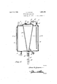
- Figure 1 is a top plan view of the improved lubricator as constructed in accordance with the present invention.
- Fig. 2 is a central vertical sectional view 30 through the same, and taken on line 2--2 of Fig. 1, and
- Fig. 3 is a horizontal section on the plane of the line 8-3 of Fig. 2.
- the numeral 4 designates a cylinder having a suitable drain 5 at its bottom, and a suitable filler plug or cap 6 at its top.
- the numeral 7 merely designates in a general way, a fluid gauge. Incidentally,fluid under pressure is intended to enter this container throughthe medium of the intake pipe 8.
- This fluid under pressure is forced out from the container by way of a pipe conduit generally designated by the reference character 9
- the latter part is centrally arranged within the main fluid pressure container 4:. It is preferably in the nature of a tapered hopper. At its bottom it is provided with a drain 16 and is connected with a lubricant feed supply pipe 17 having a check valve 18 to prevent back pressure, and a control valve 19.
- the reference character 20 designates a filler plug throughwhich lubricant is placed into the receptacle 15. It has always been hard to keep oil out of'a boiler in a power or heating plant where engines and pumps are used, and where the exhaust steam is used to heat the boiler feed water. With this graphitelubricator no oil need be used and it will work anywhere you have steam or water pressure. It can be used for oil, graphite and oil, or graphite and water.
- a force feed lubricator In a force feed lubricator, a condensing tank having inlet and outlet ports therein, a conical lubricant container located in the tank with its ends projecting therefrom, a conduit passing through one end of the tank andconnected with the large end of the container, that end of the. conduit within the tank being located a slight distance from that end of the tank through which the small end of the container passes, a valve in the outer part of the conduit, a discharge pipe c011- nected with the small end of the container and having a valve therein, and means for introducing lubricant into the container.
Landscapes
- Engineering & Computer Science (AREA)
- General Engineering & Computer Science (AREA)
- Mechanical Engineering (AREA)
- Loading And Unloading Of Fuel Tanks Or Ships (AREA)
Description
April-"12, 1932- J. E. GROVEN I FORCE FEED LUBRICATOR Filed Aug. 15, 1929 2 Sheefis-Sheet Inventor A ttomey Patented Apr. 12, 1932 UNETED STATES JESS EDWARD GROVEN', F MIDWEST, WYOMING FORCE FEED LUBRICATOR Application filed August 13, 1929. Serial No. 385,614.
' This invention relates to lubricating appliances, of the force feed type, and it has more particular reference to a structure which is especially made to operate under the influe ence of a combination of force feed fluids, for instance water, under pressure, or steam under pressure, whichever is desired.
Briefly stated, the invention has reference to a structure of this class which embodies a lubricant container surrounded by .a fluid pressure container, appropriate intake and drain means for both of said containers, and a delivery connection between the containers, whereby the fluid under pressure, may enter the lubricant container to forcibly eject the lubricant therefrom through the feed line, which is connected with the machinery to be lubricated.
My idea involves the utilization of a compact and convenient structural arrangement of parts which is practical, and otherwise efficient and simple in fulfilling the requirements of a structure of this class in a highly satisfactory manner.
In the drawings Figure 1 is a top plan view of the improved lubricator as constructed in accordance with the present invention.
Fig. 2 is a central vertical sectional view 30 through the same, and taken on line 2--2 of Fig. 1, and
Fig. 3 is a horizontal section on the plane of the line 8-3 of Fig. 2.
The complete assemblage of parts may Well 35 be seen in Fig. 2, wherein it will be observed that the numeral 4 designates a cylinder having a suitable drain 5 at its bottom, and a suitable filler plug or cap 6 at its top. The numeral 7 merely designates in a general way, a fluid gauge. Incidentally,fluid under pressure is intended to enter this container throughthe medium of the intake pipe 8.
This fluid under pressure is forced out from the container by way of a pipe conduit generally designated by the reference character 9 This includes a pipe section 10 which depends into the container 4 and terminates adjacent the bottom thereof. This includes a control valve 11, union 12, and an elbow connection 13 with a cap 14 provided on the upper end of the lubricant receptacle or container 15. 1
The latter part is centrally arranged within the main fluid pressure container 4:. It is preferably in the nature of a tapered hopper. At its bottom it is provided with a drain 16 and is connected with a lubricant feed supply pipe 17 having a check valve 18 to prevent back pressure, and a control valve 19.
The reference character 20 designates a filler plug throughwhich lubricant is placed into the receptacle 15. It has always been hard to keep oil out of'a boiler in a power or heating plant where engines and pumps are used, and where the exhaust steam is used to heat the boiler feed water. With this graphitelubricator no oil need be used and it will work anywhere you have steam or water pressure. It can be used for oil, graphite and oil, or graphite and water.
For oil the pressure must come in at the bottom and the outlet must come out at the top. The same applies to graphite and oil. For graphite and water the pressure must come in at the top of the tank and the outlet at the bottom of the tank. When using oil or graphite and oil, the lubricator is simply turned upside down, allowing the pressure to come in at the bottom of the lubricator and the outlet at the top. I have found that the lubricator Works better if the steam pressure comes from back of the throttle valve and for water pressure it must come off of the discharge line or where the pressure is the highest.
For graphite and water :-First fill the graphite tank full of graphite, thenturn the steam in the water tank and let it condense to water, then turn the water into the graph- 90 ite tank at full pressurethus mixing the graphite and water and allowing the graphite to absorb the water, then open the bottom valve on the graphite tank a little (the amount used is regulated by this valve). There must be a check valve used when lubricator is used on a steam pump or a steam engine in order not to have back pressure on the lubricator.
A careful consideration of the description in connection with the drawings will enable the reader to obtain a clear understanding of the complete assemblage, the features and advantages, as well as the operation of the invention. Therefore, a more lengthy description is believed to be unnecessary.
Minor changes in shape, size, and materials, coming within the field of invention claimed, may be resorted to in actual practice if desired.
Having thus described my invention, what I claim as new is In a force feed lubricator, a condensing tank having inlet and outlet ports therein, a conical lubricant container located in the tank with its ends projecting therefrom, a conduit passing through one end of the tank andconnected with the large end of the container, that end of the. conduit within the tank being located a slight distance from that end of the tank through which the small end of the container passes, a valve in the outer part of the conduit, a discharge pipe c011- nected with the small end of the container and having a valve therein, and means for introducing lubricant into the container.
In testimony whereof I affix my signature.
JESS EDlVARD GROVEN.
Priority Applications (1)
| Application Number | Priority Date | Filing Date | Title |
|---|---|---|---|
| US385614A US1853765A (en) | 1929-08-13 | 1929-08-13 | Force feed lubricator |
Applications Claiming Priority (1)
| Application Number | Priority Date | Filing Date | Title |
|---|---|---|---|
| US385614A US1853765A (en) | 1929-08-13 | 1929-08-13 | Force feed lubricator |
Publications (1)
| Publication Number | Publication Date |
|---|---|
| US1853765A true US1853765A (en) | 1932-04-12 |
Family
ID=23522145
Family Applications (1)
| Application Number | Title | Priority Date | Filing Date |
|---|---|---|---|
| US385614A Expired - Lifetime US1853765A (en) | 1929-08-13 | 1929-08-13 | Force feed lubricator |
Country Status (1)
| Country | Link |
|---|---|
| US (1) | US1853765A (en) |
-
1929
- 1929-08-13 US US385614A patent/US1853765A/en not_active Expired - Lifetime
Similar Documents
| Publication | Publication Date | Title |
|---|---|---|
| US1853765A (en) | Force feed lubricator | |
| US32061A (en) | Improved feed-water apparatus for steam-boilers | |
| US1537687A (en) | Oil and air pumping system | |
| US1823154A (en) | Fluid induction device | |
| US1576982A (en) | Lubricant-dispensing apparatus | |
| US1356166A (en) | Atomizer | |
| US1526646A (en) | Automatic lubricator | |
| CN207229484U (en) | Water turbine oil pressure device oil return box with oil spill gathering device | |
| US1944320A (en) | Fuel pump for internal combustion engines | |
| US199745A (en) | Improvement in lubricators for steam-engines | |
| US138343A (en) | Improvement in lubricators for steam-engines | |
| US1125135A (en) | Lubricating device. | |
| US1293216A (en) | Boiler-filler. | |
| US1692202A (en) | Steam-engine lubricator | |
| US836406A (en) | Valve. | |
| US267692A (en) | Oil and water injector | |
| US588566A (en) | Lubricator | |
| US1676141A (en) | Feed-water heater for locomotive boilers | |
| US1663052A (en) | Automatic oil pump with sight feed | |
| US777765A (en) | Cylinder-lubricator. | |
| US813051A (en) | Pump. | |
| US848873A (en) | Pipe-coupling. | |
| US562876A (en) | James wilson | |
| US1249412A (en) | Automatic decarbonizer. | |
| US104914A (en) | Improvement in impermeators tor steam-engines |