US1853745A - Circuit breaker operator - Google Patents
Circuit breaker operator Download PDFInfo
- Publication number
- US1853745A US1853745A US409848A US40984829A US1853745A US 1853745 A US1853745 A US 1853745A US 409848 A US409848 A US 409848A US 40984829 A US40984829 A US 40984829A US 1853745 A US1853745 A US 1853745A
- Authority
- US
- United States
- Prior art keywords
- breaker
- shaft
- finger
- arm
- rod
- Prior art date
- Legal status (The legal status is an assumption and is not a legal conclusion. Google has not performed a legal analysis and makes no representation as to the accuracy of the status listed.)
- Expired - Lifetime
Links
- 230000033001 locomotion Effects 0.000 description 39
- 239000004020 conductor Substances 0.000 description 22
- 230000002159 abnormal effect Effects 0.000 description 8
- 230000000694 effects Effects 0.000 description 8
- 230000006835 compression Effects 0.000 description 5
- 238000007906 compression Methods 0.000 description 5
- 238000009877 rendering Methods 0.000 description 4
- 238000010586 diagram Methods 0.000 description 3
- RTZKZFJDLAIYFH-UHFFFAOYSA-N Diethyl ether Chemical compound CCOCC RTZKZFJDLAIYFH-UHFFFAOYSA-N 0.000 description 2
- 230000005540 biological transmission Effects 0.000 description 2
- 230000000717 retained effect Effects 0.000 description 2
- 235000014443 Pyrus communis Nutrition 0.000 description 1
- 230000001143 conditioned effect Effects 0.000 description 1
- 230000008878 coupling Effects 0.000 description 1
- 238000010168 coupling process Methods 0.000 description 1
- 238000005859 coupling reaction Methods 0.000 description 1
- 125000004122 cyclic group Chemical group 0.000 description 1
- 230000000994 depressogenic effect Effects 0.000 description 1
- 230000005484 gravity Effects 0.000 description 1
Images


Classifications
-
- H—ELECTRICITY
- H01—ELECTRIC ELEMENTS
- H01H—ELECTRIC SWITCHES; RELAYS; SELECTORS; EMERGENCY PROTECTIVE DEVICES
- H01H75/00—Protective overload circuit-breaking switches in which excess current opens the contacts by automatic release of mechanical energy stored by previous operation of power reset mechanism
- H01H75/02—Details
- H01H75/04—Reset mechanisms for automatically reclosing a limited number of times
Definitions
- This invention relates generally to apparatus for automatically operating electrical circuit devices. It has articular application in conjunction wit electrical power L transmission systems, for automatically reclosing circuit breakers. v v
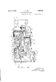
- Figure 1 is a side elevational view, illustrating a circuit breaker operator constructed in accordance with this invention, and taken along the section line 11 of Fig. 2.
- FIG. 2 is a cross sectional view taken along theline 2-2 of Fig. 1.
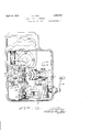
- Fig. 3 is an enlarged cross sectional view taken along the line 3-3 of Fig. 2, certain parts being omitted for the sake of clarity.
- Fig. 4 is an enlarged side elevational view in cross section, illustrating certain parts which are utilized in conjunction with the movable timing member.
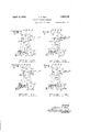
- Fi 5 is a cross sectional detail taken along the line of Fig. 3.
- Fig. 6 is a fragmentary cross sectional detail taken along the line 66 of Fig. 5.
- Fig. 7 is a dia ammatic detail illustrating the mechanism or effecting operation of the motor limiting switch.
- Fig. 8 is a view similar to Fig. 7, illustrating another operating position for the mechanism shown in Flg. 7.
- Fig. 9 is a cross sectional detail on an enlarged scale, taken along the line 9-9 of 60 Fig. 1.
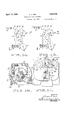
- igs. 10 to 15 inclusive are diagrammatic views illustrating the mode of operation of my apparatus.
- Fig. 16 is a cross sectional detail taken along the line 16-16 of Fig. 4, illustrating the overrunning clutch utilized in my drive gearing.
- Fig. 17 is a detail illustrating the device for locking the manual pull rods.
- Fig. 18 is a circuit diagram illustrating an be employed.
- Fig. 19 is a cross sectional detail taken along the line 19-19 of Fig. 4.
- the invention can be outlined briefly as utilizing spring or equivalent means for storing the energy of a motive device, such as an electrical motor.
- Energy stored in the spring means is controlled by a pair of trippable devices, such as a pair of toggles, one of which when tripped efiects opening of the breaker, and the other effecting a reclosing operation.
- a movable timing member is provided which in conjunction with additional means, causes tripping of one of the toggle devices to effect a reclosing operation a predetermined time following opening of the breaker.
- suitable lockout means is provided whereby under certain conditions the apparatus is rendered inoperative until reset.
- a housing 10 for enclosing the prina5 cipal operating parts of the appartus.
- This housing includes the front and rear walls 11 and 12, side walls 13 and 14, and a base portion 16. Side walls 13 and 14-are provided with convenient removable closure plates 17 and 18.
- a rocker arm 19 carried by shaft 21.
- a rod or link 22, connected to arm 19, serves as a means for applying motion to thecircuit breaker or breakers.
- an electrical motor 24 positioned within the housing upon base portion 16.
- This motor is arranged to drive a rotatable shaft 26, thru a suitable speed reducing gearing 27.
- the particular gearing 27 which has been illustrated in Figs. 1 and 2, consists of a housing 28 within which a shaft 29 is j ournaled. This shaft is directly connected to the shaft of motor 24, thru coupling 31.
- a worm 32 is fixed to shaft 29, and is adapted to engage a worm gear 33, this latter gear being fixed to another rotatable shaft 34.
- Another gear 36 carriedby shaft 34 engages a gear 37 fixed to shaft 26.
- a manual crank 38 is shown journaled in the front wall 11 of housing 10, and is adapted to be clutched with an extension of shaft. 34.
- Shaft 34 is directly connected with gear 36, but has an overrunning clutch connection with gear 33 as shown in Fig. 19.
- a clutch of this character is well known in the art and need not be described in detail. It can consist of spring pressed balls 39 disposed in the hub of gear 33, and arranged to engage the'periphery of shaft 34. Therefore gear 36 can be rotated by crank 38, without rotating gear 33, but when motor 24 is operated to rotate shaft 34, gear 36 is driven to drive gear 37 and shaft 26.
- Gear 37 ordinarily rotates at a relatively slow rate of speed, and a member 41 projecting from one face of the same, performs a timing function in conjunction with other parts to be presently described.
- shaft 26 is directly connected to a crank 42, which carries a crank pin 43.
- the means for storing the energy of motor 24 and for applying force to rocker arm 19, has been represented by a spring structure 44.
- the form of this spring structure which has been illustrated, consists of a rod 46 extending telescopically within a sleeve '47.
- the lower end of sleeve 47 has a journal block or member 48 fixed to the same, which member is j ournaled upon crank pin 43.
- a compression spring 49 surrounds sleeve 47, and has its upper end seated upon an annular shoulder 51 secured to the upper end of sleeve 47.
- links 54 and 56 are shown pivotally connected to the upper end of rod 46, by means of pin 57.
- Device 61 includes links 63 and 64 which are pivotally connected together, link 63 bein carried by a shaft 66.
- ink 64 has a pin and slot connection 67 with one end of a lever 68 Lever 68 is in turn carried by a shaft 69.
- Link 56 is connected toan arm 71 b means of pin 72, and arm 71 is also carried y shaft 69 and is rotatable together with lever 68.
- Toggle device 62 likewise consists of links 73 an 74 which are pivotally connected together, link 73 being carried by shaft 76.
- ink 74 is in turn pivotally connected toarm 58, by means of pin 77.
- crank arm 19 when toggle device 62 is broken, spring structure44 pulling upon rod 46, tends to move pivot pin 57 downwardly to rotate arms 19 and 58 in a clockwise direction.
- the position of crank arm 19 shown in solid lines in Fig. 1 corresponds to open position of the breaker, while that position shown in dotted lines corresponds to closed position.
- crank arm 19 After tripping of toggle device 62, crank arm 19 is moved to the position shown in dotted lines, or in other words is moved to close the breaker.
- Toggle device 62 can therefore be termed the closing toggle. If toggle device 61 is tripped subsequent to crank arm 19 is free to return to its initial position, corresponding to open position of the breaker, thru force applied by a gravity or sprin bias located in the circuit breaker.
- a suitable solenoid 79 is mounted within housing 10, and the plunger of this solenoid is adapted to engage and actuate a finger 82 (Fig. 2).
- Finger 82 is also carried by shaft 66, and its movement carries with it link 63.
- a 83 is provided to normally bias finger 82 downwardly, and to bias to gle device 61 to set position.
- Set position of toggle device 61 can be adjusted by a set screw 84, threaded into link 63, and adapted to engage a fixed .stop 86 (Fig. 2).
- Tripping of toggle device 62 can also be controlled from a remote point, byenergizing a similar solenoid 87.
- the plunger of this solenoid is adapted to raise a finger 88 carried tates together with finger 88, so that raising of this-finger by solenoid 87 causes tripping of toggle device 62.
- Toggle device 62 is ikewise preferably biased toward set osition, by means of a spring 89 (Fig. 2) w ich 73 in a clockwise direction as viewed in Fig. 1.
- Arm 94 is preferably biased by means of spring 97 (Fi 3), so as to rotate arm 94 in a countercloc wise direction as viewed in Fig. 1.
- another arm 98 is fixed to shaft 96, and this arm 98 has a bifurcated portion 99 pivotall connected with a finger 101.
- Pin 102 whic connects arm 98 and finger 101 also serves to connect arm 98 with a shackle 103 rovided upon the lower end of a rod 104. T e function of this rod will be presently described.
- Suita spring 106 normally same in a cloc ise direction as viewed in Fig. 1, and also to bias rod 104 towards the left as viewed in Fig. 1. Clockwise rotation of finger 101 relative to arm 98 is definitely limited by a portion 107, which engages blfurcated portion 99.
- Rod 104 serves the purpose of tripping toggle device 62. Accordingly its upper end normally underlies Bennett er 109, this finger being carried by shaft 76 %Fig. 4) and rotatable together with finger 88 and link 73. Therefore upward movement of rod 104 to lift finger 109, serves to rotate link 73 to trip toggle 62.
- Rod 104 is preferably loosely guided as by means of a bracket 111.
- This guide means is preferably such that when rod 104 is in fully raised position, as-
- finger 109 can return to normal osition shown in solid lines in this view.
- am member 112 (Fig. 4) is likewise carried by shaft 76, and is rotatable together with finger 109.
- cam member 112 takes the position s own in dotted lines in this view, and thus moves rod 104 to one side, so that when this rod remains in raised position, finger 109 canreturn to its initial position.
- These members 117 are rovided with parallel slots 118, thru which t e laterally bent portion 119 of rod 114 extends.
- a lug 121 secured to portion 119 serves to retam and guide this portion along members 117.
- Members 117 are also both connected to a shaft 122, this shaft being in turn supported by suitable bracket 123.
- An arm 124 is also fixed to shaft 122 and is connected to the plunger of a solenoid 126, the function of which will be presently described.
- Another lever 127 is fixed to shaft 122 and is pivotally connected to the lower end of rod 128.
- Shaft 122 is normally biasedto rotate in a clockwise direction as viewed in Fig. 4, by means of a suitable spring 129 (Fig. 3).
- R0- tation in a clockwise direction is limited so that members 117 normally assume the position shown in full lines in Fi 5.
- rocking of arms 19 and 58 will cause portion 119 to slide up and down slots 118.
- the function of members 117 and slots 118 is therefore to cause portion 119 to travel a predetermined path, and with a predetermined relationship with respect to. finger 101.
- the uppermost position of portion 119 corresponds to open condition of the associated breaker, and the lowermost position corresponds to closed condition.
- finger 101 is out of the path of travel of portion 119, al-
- finger 101 may trip over portion 119 when this portion moves downwardly at the same time that the finger moves upwardly, as when toggle device 62 is tripped by upward movement of rod 104.
- arm 98 is raised breaker trips en, causes this portion to engage beneath t e end of finger 101, thus rais raised position, if the breaker tri s open, and
- Man ual means of this character can consist of a pull rod 132 (Fig. 9) extended thru the front wall 11 of houslng 10, and provided with a convenient button or knob 133.
- a compression spring 134 serves to bias rod 132 in one direction.
- the inner end of rod 132 is connected with a lever 136, rotatably carried by shaft 137.
- a finger 138 is also carried by shaft 137 and is rotatable'together with lever 136. This finger is adapted to engage another finger 141 carried by shaft 76 and rotatable together with link 73.
- lever 136 When knob 133 is pulled, lever 136 is rotated in a clock- Wise direction as viewed in Fig. 1, to likewise rotate finger 138, (Fig. 9) thus causing finger 141 and link 7 3 to be rotated in a counterclockwise direction to trip toggle device 62.
- toggle device 62 When toggle device 62 is tripped, it is apparent that rocker arm 19 swings to the right as viewed in Fig. 1 to close the breaker, and at the same time, portion 119 (Fig. 3) moves downwardly relative to slotted member 117,
- means which can be manually operated to open the breaker and lock out the apparatus.
- This means can consist of a pull rod 146 slidably extended thru the front wall 11 of housing 10, and provided at its outer end with a manual button or knob 147.
- This rod is also biased in one direction by means of a compression spring 148.
- the inner end of rod 146' is connected to a lever 149, also carried by shaft 137 and rotatable independently of lever 136.
- Finger 151 is carried by shaft 137, and is rotatable together with lever 149. This finger is adapted to engage and move a finger 152 (Fig. 1), carried y shaft 66 and rotatable together with link 63 of toggle device 64.
- lever 153 which is pivotally connected to the upper end of rod 128.
- lever 149 and finger 151 are rotated in a clockwise direction as viewed in Fig. 1, thus causing rotation of finger 152 and link 63 in a counterclockwise the breaker opens, it engages the end of finger 101, thus lifting this finger together with arm 98 to move cam surface 92 out of the pathof movement of timing member 41.
- I preferably provide inter-.
- Suitable means of this character can consist of an arm 150 (Fig. 16) carried by shaft 137, and rotatable together with lever 149 and finger 151. This arm is adapted to engage the face of a lug 155, this lug being carried by shaft 76 and rotatable together with finger 141.
- lug 155 can be formed integral with finger 141, as shown in Fig. 16. It is apparent that engagement of arm 150 with lug 155 prevents pulling of rod 146 until lug 155has been moved to an out of the way position by tripping toggle device 62. In other words the opening toggle 61 cannot be tripped by pulling rod 146, until the closing toggle 62 has been tripped.
- a conventional switch 156 mounted upon the back wall 12 of housing 10, andhaving its movable member connected with a bar .157.
- the upper end of bar 157 is connected to arm 58 by means of in 158.
- Another conventional switch 159 (Fig. 1) is mechanically connected so as to be operated according. to movement of arms 71 and 68.
- an arm 161 carried by shaft 69 and rotatable to ether with levers 71 and 68.
- Arm 161 has a ifurcated end portion 162, which slidably embraces a depending rod 163.
- the lower end of rpd 163 is provided with a pin 164 (Fig. 2), and this pin is guided by a member 166 (Figs. 7-8).
- Pin 164 isadapted to cooperate with a pivoted lever 167, which in turn is in tended to be tripped by a pin 168 projecting from crank pin 43.
- a compression spring 169 surrounding rod 163, has its lower end seated upon a collar 175 which is fixed to rod 163, and has its u per end seated u on a collar 172 sildably lsposed upon ro 163.
- Spring 169 therefore normall presses collar 172 against the lower face of ifurcated portion 162, and when lever 161 is rotated in a counterclockwise direction as viewed in Fig. 1, against the force of spring 169, rod 163 is biased downwardly.
- An annular shoulder 174 is secured to the upper end of rod- 163, and is ada ted to be engaged by the upper edge of bi Inted portion ,162.
- Lever 167 is pivoted by means of pin 176, and its upper end is provided with a cam surface 177. This cam surface preferably has one portion a which is relatively flat and another portion b inclined relative to portion a. The other end of lever 167 is provided with a cam sur face 178, adapted to be engaged by pin 168.
- Lever 167 is normally biased to rotate in a clockwise direction, as by means of tension spring 180.
- Rod 163 is also connected to the movable member of switch 159 by means of arm 175 (Fig. 1).
- crank pin 43 and also pin 168 are rotated both for the purpose of retensioning spring structure 44 and in order to effect a subsequent automatic reclosing operation.
- pin 168 engages cam surface 178 of lever 167, thus ,rotating this lever in a counterclockwise direction and causing cam portion a to be disengaged from the lower end of pin 164.
- lever 167 When lever 167 has been rotated a sufficient amount to bring the lower end of pin 164 into contact with inclined cam surface 5, the force of spring 169 is sufiicient to cause continuous movement of lever 167, until this lever occupies the position shown in Fig. 6.
- switch 159 When rod 163 and pin 164 are in their fully depressed position shown in Fig. 6, switch 159 has been actuated to disrupt or open the motor circuit.
- lever 71 takes the position shown in dotted lines in Fig. 1, thus causing arm 161 to raise rod 163 and pin 164 out of engagement with cam surface 177, and allowing lever 167 to rotate in a clockwise direction back to its initial position.
- the motor circuit is then again closed, to initiate cyclic movement of pin 168. It hould be noted that before pin 168 comes to rest after a rewinding operation,
- lever 167 may come back to its initial position, without engaging pin 168.
- a plate 181 is disposed between the knobs 133 and 147, and is slidably retained upon the front wall 11 by means of a headed pin 182, passing thru a slot 183 in the plate.
- the side edges 184 are inclined as indicated, so that when the plateis in raised position, the side edges serve to interlock with grooves 185,
- Fig. 18 there is shown a circuit diagram which can be utilized with my apparatus.
- lines 186 represent a three phase transmission line controlled by the circuit breaker 187.
- Overload relays 188 are associated with lines 186 by means of current transformers 189.
- the contacts of relays 188 are connected together and are in series with a local circuit including conductors 191 and 192.
- Switches 159 and 156 are provided with a plurality of sets of contacts, which have been designated 1, 2, 3 and 4 for switch 159 and 5, 6, 7 and 8 for switch 156.
- One terminal of opening solenoid 78 is connected to i one side of contacts 6, and the other terminal is connected to conductor 191.
- One terminal of closing solenoir 89 is connected to one side of contacts 4, and its other terminal is connected to conductor 192, in series with switch 193.
- Lockout solenoid 126 has one terminal connected to conductor 191, and its other terminal connected to conductor 192, thru switch 194.
- the terminals of motor 24 are connected to corresponding elements of contacts 1 and 3, and the other elements of these contacts are connected to conductors 196 and 197.
- the other terminal of conductor 196 is connected to one side of the contacts 8, and the other terminal of conductor 197, is connected to one side of contacts 5 and 6.
- Conductor 198 connects between contacts 4, 5 and 8 as shown.
- Conductors 201 and 202 represent direct current supply lines, and are connected to con-' ductors" 196 and 197, by conductors 203 and 204.
- Conductor 192 is connected to conductor 201 by means of conductor 206.
- Colored signal lamps 207 and 208 can be connected in series across conductors 201 and 202, and the center connection between these lamps is con-- back to conductor 202.
- Energizing of sole noid 78 is followed by immediate opening of the breaker, and switch 156 is then operated to close contacts 5 and 7, and open contacts 6 and 8.
- Switch 159 is alsooperated to close contacts 1 and 3 and open contacts 2 and 4. The circuit to motor 24 is then closed to to wind thebreaker operator.
- switch 159 is again operated to open contacts 1 and 3 an close contacts 2 and 4.
- Switch 156 is also reconditioned to close contacts 6 and 8. If the breaker should again be tripped open immediately or within a predetermined time following its automatic reclosure, motor 24 will continue to rewind the breaker operator, and to recondition switch 159 to interrupt the motor circuit, while switch 156 will again be conditioned to close contacts 5 and 7. To reset the breaker operator, an operator can close switch 193 to energize closing solenoid 89.
- switch 194 is closed to energize lockout solenoid 126. This operation causes the breaker to open and locks out the breaker operator until reset by closing solenoid 89, or until a manual reclosing operation is effected.
- Fig. 10 shows the parts of the operator in a position corresponding to closed condition of the breaker. It will be noted that at this time toggle device 62 is broken, while toggle device 61 is set. Upon 'trippin toggle device 61, v by energizing solenoi 79, the external bias provided in the associated circuit breaker, represented by compression sprin 211, moves arm 19 to the position shown inI ig. 11. Portion 119 now occupies its uppermost position in slot 118. As has been previously explained in connection with the circuit diagram of Fig.
- member 41 will have moved intoengagement with member 91, to raise arm 98 and finger 101, as illustrated in Fi 13. Raising of arm 98 and its associated r0 104, causes tripping of toggle 62, thus causing rocker arm 19 to move to the position shown in Fi 13, correspondin to closed position 0 the assoclated circuit breaker. WVhile member 41 is traveling thru the angle 9, it continues in contact with member 91, and this period of time is definitely predetermined. In the event that the breaker remains closed while member 41-is moving thru angle 9, member 41 and pin 43 come to rest by opening of the motor c1rcuit, in the positions represented by dotted lines and indicated at 41a and 43a (Fig. 13).
- toggle device 61 To reset .or recondition the operator, toggle device 62 is tripped, thus causing portion 119 to release fin er 101 and arm 98.
- ig. 15 illustrates the manner in which the apparatus can be locked out by manually pulling rod 146.
- members 117 are swung to a position in which upward movement of portion 119 will engage and lift finger 101, and toggle device 61 will be tri ped. The operator will then remain loc ed out, until the breaker is reclosed.
- a member movable in one direction to efiect closing of the breaker, spring means for moving said member in a direction to close the breaker, trippable means adapted when set to render actuation of said spring means inefi'ective, a movable timing member, and means controlled by said timing member for effecting tripping of said trippable means.
- a member movable in one direction to eiiect closing of the breaker, spring means for moving said member in a direction to close the breaker, trippable means adapted when set to render actuation of said spring means ineffective, a movable timing member, and mechanical means actuated by said tuning breaker, spring means member for tri ping said trippable means.
- a member movable to effect closing of the for moving said memher in a direction to close the breaker trippable means adapted when set to render said spring means inactive, a movable timing member, another member normally in the path of movement of said timing member whereby it is engaged and moved by the same, means for tripping said trippable means responsive to movement of said other member b the timing member, and means for retaining said other me her out of the path of movement of the timing member.
- timing member adapted to be set into motion upon opening of the breaker, another member normally in the path of movement of the timing member whereby it is engaged and moved by the same, said members being in cooperating engagement for a substantial time period during movement of the timing member, means for eifecting automatic reclosing of: the breaker following opening of the same due to abnormal conditions on the breaker line, said means being'operative upon movement of said other member by said timing member, and means for rendering said reclosing means ineffective to cause a reclosure in the event thatan opening of the breaker occurs while said members are in engagement.
- a timing member adapted to be set in motion upon opening of the breaker, another mem-' ber normally in the path of movement of the. timing member whereby-it is engaged by the same and moved from a normal position to a second position, means for effecting automatic reclosing of the breaker following opening of the same due to abnormal line conditions, said means being operative upon movement of said other member from said normal to said second position, means for rendering said reclosing means ineffective to cause a reclosure in the event that an opening of the breaker occurs while said members are in engagement, and means for locking said other member in a position out of the path of movement of said timing member.
- timing member adapted to be set in motion upon opening of the breaker, another member normally in the path of movement of the timing member whereby it is engaged by the same and moved from a'normal position to normal to said second position
- timing member adapted to set in motion upon opening of the breaker responsive to an abnormal condition on the line, another member normally in the path of movement of the timing member whereby it is engaged and moved by the same, said members being in cooperative engagement for a substantial time period during movement of the timing member, means for effecting automatic reclosing of the breaker following opening of the same due to an abnormal line condition;
- said means including a movable member adapted to be connected to the breaker, spring means for moving said member, a toggle for retaining the spring in stressed condition, means actuated by said other member for tripping said toggle, and means for rendering said reclosing means i nefiective to cause a subsequent reclosure in the event that an opening of the breaker occurs while said members are in engagement.
- a member movable to effect closing and opening movements of'a breaker spring means adapted to move said member in opposite directions
- two trippable means adapted to retain said spring means inactive whereby said member is moved in one direction to tripping one of said trippable means and is moved in an opposite direction upon tripping the other trippable means
- means for resetting said trippable means and for stressing said spring means a timing'member set in movement by operation of said resetting means, and means controlled by said timing member for tripping ing movementsof a breaker
- two trippable means adapted to retain said spring means inactive whereby said member is moved in one direction to open the breaker upon tripping one of said trippable means and is moved in an opposite direction upon tripping the other trlppable means
- means for resetting said trippable means and for stressing said spring means a timing member set in movement by operation of said resetting means
- a member movable for effecting an 5 operation of said mechanism a plate su ported adjacent said'member and slidable between two-limiting positions, said plate hav-' ing a portion thereof adapted to interfit a groove formed on said member forone of I.) said limiting positions, and means for locking said plate in said one limiting position whereby said member is locked aga nst movement of the same.
Landscapes
- Breakers (AREA)
Description
' April 12, 1932. REA 1,853,745
Camp; ea
A TTOR NE YS April 12, 1932. I REA 1,853,745
CIRCUI'I BREAKER OPERATOR (Z6073; C Rea A TTORNE YS April 12, 1932.
J. C. REA
CIRCUIT BREAKER OPERATOR Filed Nov. 26, 1929 8 Sheets-Sheet 3 K 7. 9 y 7 4 3 a J M 4 w H H H M L m 2 1 m Jr Y n 5 7 4 7 6 .0? 2:5; (3 E 0 r E/ r A M I 2 1| 2 7 J 9 v p 41/ 5.1
April 12, 1932. J. c. REA- 1,853,745
CIRCUIT BREAKER OPERATOR Filed Nov. 26, 1929 8 Sheets-Sheet 5 I Ed .L E1 d INVENTOR.
Cvna: 6 Eva April 12, 1932.
J. c. REA 1,853,745
CIR-QUIT BREAKER OPERATOR 8 Sheets-Sheet 6 Filed Nov. 28, 1929 IN V EN TOR. 049/7051; C Rea.
ATTORNEYS.
April 12, 1932. J. c. REA 1,853,745
' CIRCUIT BREAKER OPERATOR I Filed Nov. 26, 1929 8 Sheets-Sheet '7 C/ IN VEN TOR. amp: 6. R652 MVZEZ E A TTORNEYS.
J. c. REA 1,853,745
C IRCUIT BREAKER OPERATOR A ril 12, 1932.
Filed Nov. 26, 1929 8 Sheets-Sheet 8 INVENTOR. 50751: 6. P662 await.
ATTORNEYS.
Patented Apr. 12, 1932 UNITED STATES PATENT OFFICE TAKES C. BEA, OF SAN FRANCISCO, CALIFORNIA, ASSIGNOR TO PACIFIC ELECTRIC EANUFACTURING CORPORATION, OF SAN FRANCISCO, CALIFORNIA, A CORPORA- TION OF CALIFORNIA CIRCUIT BREAKER OPERATOR Application filed November 26, 1929. Serial No. 409,848.
This invention relates generally to apparatus for automatically operating electrical circuit devices. It has articular application in conjunction wit electrical power L transmission systems, for automatically reclosing circuit breakers. v v
It is an object of this invention to devise novel and improved apparatus of the above character, which w1ll make possible the omislo sion of special electrical circuits interconnecting a movable timing member with breaker o crating mechanism.
It is a urther object of this invention to devise a novel automatic breaker operator, which will automatically lockout and prevent further breaker reclosures in the event that the breaker trips open within a predetermined time period following a reclosing operation.
It is a further object of the invention to devise a breaker operating apparatus havelectrical system in which my invention can mg novel means which will enable it to be locked out at the will of the operator or supervisor in the event that subsequent automatic reclosures are not desired.
Further objects of the invention will ap-' pear from the followingdescription in WlllCh the preferred embodiment of the invention has been set forth in detail in conjunction with the accompanying drawing.
It is to be understood that the appended claims are to be accorded a range of equiva-v lents consistent with the state of the prior art.
Referring to the drawings:
Figure 1 is a side elevational view, illustrating a circuit breaker operator constructed in accordance with this invention, and taken along the section line 11 of Fig. 2.
0 Fig. 2 is a cross sectional view taken along theline 2-2 of Fig. 1.
Fig. 3 is an enlarged cross sectional view taken along the line 3-3 of Fig. 2, certain parts being omitted for the sake of clarity.
' 5 Fig. 4 is an enlarged side elevational view in cross section, illustrating certain parts which are utilized in conjunction with the movable timing member.
Fi 5 is a cross sectional detail taken along the line of Fig. 3.
Fig. 6 is a fragmentary cross sectional detail taken along the line 66 of Fig. 5.
Fig. 7 is a dia ammatic detail illustrating the mechanism or effecting operation of the motor limiting switch.
Fig. 8 is a view similar to Fig. 7, illustrating another operating position for the mechanism shown in Flg. 7.
Fig. 9 is a cross sectional detail on an enlarged scale, taken along the line 9-9 of 60 Fig. 1.
igs. 10 to 15 inclusive are diagrammatic views illustrating the mode of operation of my apparatus.
Fig. 16 is a cross sectional detail taken along the line 16-16 of Fig. 4, illustrating the overrunning clutch utilized in my drive gearing.
Fig. 17 is a detail illustrating the device for locking the manual pull rods.
Fig. 18 is a circuit diagram illustrating an be employed.
Fig. 19 is a cross sectional detail taken along the line 19-19 of Fig. 4.
The invention can be outlined briefly as utilizing spring or equivalent means for storing the energy of a motive device, such as an electrical motor. Energy stored in the spring means is controlled by a pair of trippable devices, such as a pair of toggles, one of which when tripped efiects opening of the breaker, and the other effecting a reclosing operation. A movable timing member is provided which in conjunction with additional means, causes tripping of one of the toggle devices to effect a reclosing operation a predetermined time following opening of the breaker. In combination with the features herein outlined, suitable lockout means is provided whereby under certain conditions the apparatus is rendered inoperative until reset.
Referring to the drawings for a detailed description of one practical embodiment, there is shown a housing 10 for enclosing the prina5 cipal operating parts of the appartus. This housing includes the front and rear walls 11 and 12, side walls 13 and 14, and a base portion 16. Side walls 13 and 14-are provided with convenient removable closure plates 17 and 18. For making mechanical connections with one or more circuitbreakers or equivalent devices, there is provided a rocker arm 19 carried by shaft 21. A rod or link 22, connected to arm 19, serves as a means for applying motion to thecircuit breaker or breakers.
As a suitable motive means, there is shown an electrical motor 24, positioned within the housing upon base portion 16. This motor is arranged to drive a rotatable shaft 26, thru a suitable speed reducing gearing 27. The particular gearing 27 which has been illustrated in Figs. 1 and 2, consists of a housing 28 within which a shaft 29 is j ournaled. This shaft is directly connected to the shaft of motor 24, thru coupling 31. A worm 32 is fixed to shaft 29, and is adapted to engage a worm gear 33, this latter gear being fixed to another rotatable shaft 34. Another gear 36 carriedby shaft 34, engages a gear 37 fixed to shaft 26. In order to effect manual rotation of shaft 26 independently of motor 24, a manual crank 38 is shown journaled in the front wall 11 of housing 10, and is adapted to be clutched with an extension of shaft. 34. Shaft 34 is directly connected with gear 36, but has an overrunning clutch connection with gear 33 as shown in Fig. 19. A clutch of this character is well known in the art and need not be described in detail. It can consist of spring pressed balls 39 disposed in the hub of gear 33, and arranged to engage the'periphery of shaft 34. Therefore gear 36 can be rotated by crank 38, without rotating gear 33, but when motor 24 is operated to rotate shaft 34, gear 36 is driven to drive gear 37 and shaft 26. Gear 37 ordinarily rotates at a relatively slow rate of speed, and a member 41 projecting from one face of the same, performs a timing function in conjunction with other parts to be presently described. Externally of gear housing 28, shaft 26 is directly connected to a crank 42, which carries a crank pin 43.
The means for storing the energy of motor 24 and for applying force to rocker arm 19, has been represented by a spring structure 44. The form of this spring structure which has been illustrated, consists of a rod 46 extending telescopically within a sleeve '47. The lower end of sleeve 47 has a journal block or member 48 fixed to the same, which member is j ournaled upon crank pin 43. A compression spring 49 surrounds sleeve 47, and has its upper end seated upon an annular shoulder 51 secured to the upper end of sleeve 47. The lower end of sleeve 47 is seated upon a collar 52, this collar being fixed to the lower end of rod 46 but being slidable upon sleeve 47 It is therefore evident that when rod 46 is moved away from member 48 and crank pin 43, spring 49 is stressed.
As means for connecting spring structure 1 44 with rocker arm 19, links 54 and 56 are shown pivotally connected to the upper end of rod 46, by means of pin 57. Rotatable .tends to rotate link together with rocker arm 19, and also carried by shaft 21, there is another arm 58 which is connected to link 54 by means of pin 59.
As previously explained, a pair of trippable devices are utilized to control openmg and closing movement of rocker arm 19. These devices, in the form of toggles, have been indicated generally at 61 and 62. Device 61 includes links 63 and 64 which are pivotally connected together, link 63 bein carried by a shaft 66. ink 64 has a pin and slot connection 67 with one end of a lever 68 Lever 68 is in turn carried by a shaft 69. Link 56 is connected toan arm 71 b means of pin 72, and arm 71 is also carried y shaft 69 and is rotatable together with lever 68. Toggle device 62 likewise consists of links 73 an 74 which are pivotally connected together, link 73 being carried by shaft 76. ink 74 is in turn pivotally connected toarm 58, by means of pin 77.
It is evident from the above description that when toggle device 62 is broken, spring structure44 pulling upon rod 46, tends to move pivot pin 57 downwardly to rotate arms 19 and 58 in a clockwise direction. The position of crank arm 19 shown in solid lines in Fig. 1, corresponds to open position of the breaker, while that position shown in dotted lines corresponds to closed position. After tripping of toggle device 62, crank arm 19 is moved to the position shown in dotted lines, or in other words is moved to close the breaker. Toggle device 62 can therefore be termed the closing toggle. If toggle device 61 is tripped subsequent to crank arm 19 is free to return to its initial position, corresponding to open position of the breaker, thru force applied by a gravity or sprin bias located in the circuit breaker.
In or er to effect tripping of toggle device 61 from a'remote point, a suitable solenoid 79 is mounted within housing 10, and the plunger of this solenoid is adapted to engage and actuate a finger 82 (Fig. 2). Finger 82 isalso carried by shaft 66, and its movement carries with it link 63. A 83 is provided to normally bias finger 82 downwardly, and to bias to gle device 61 to set position. Set position of toggle device 61 can be adjusted by a set screw 84, threaded into link 63, and adapted to engage a fixed .stop 86 (Fig. 2).
Tripping of toggle device 62 can also be controlled from a remote point, byenergizing a similar solenoid 87. The plunger of this solenoid is adapted to raise a finger 88 carried tates together with finger 88, so that raising of this-finger by solenoid 87 causes tripping of toggle device 62. Toggle device 62 is ikewise preferably biased toward set osition, by means of a spring 89 (Fig. 2) w ich 73 in a clockwise direction as viewed in Fig. 1.
tripping of toggle 62,
suitable spring .by shaft 7 6. Link 73 of toggle device 62 roable means such as tends to bias fin er 101 and tends to rotate the eeann A suitable energizing circuit is provided for motor 24, and upon tripping of toggle de vice 61, this motor circuit 1s automatically closed to rotate shaft 26. As will be presently explained, rotation of shaft 26 and crank 42 effects the stressing of spring structure 44, and the regular circular or rotative movement of member 41 is utilized to effect and time an automatic reclosing operation. Thus operating in conjunction with member 41, there is a pivoted member 91 having a cam surface 92 extending in the path of movement of member 41. A link 93 connects member 91 with an arm 94, secured to rotatable shaft 96. Arm 94 is preferably biased by means of spring 97 (Fi 3), so as to rotate arm 94 in a countercloc wise direction as viewed in Fig. 1. As shown in Fig. 3, another arm 98 is fixed to shaft 96, and this arm 98 has a bifurcated portion 99 pivotall connected with a finger 101. Pin 102 whic connects arm 98 and finger 101, also serves to connect arm 98 with a shackle 103 rovided upon the lower end of a rod 104. T e function of this rod will be presently described. Suita spring 106, normally same in a cloc ise direction as viewed in Fig. 1, and also to bias rod 104 towards the left as viewed in Fig. 1. Clockwise rotation of finger 101 relative to arm 98 is definitely limited by a portion 107, which engages blfurcated portion 99.
pleted, member 'tate arms 94 and 98.-
Movement of rod 104 serves the purpose of tripping toggle device 62. Accordingly its upper end normally underlies afin er 109, this finger being carried by shaft 76 %Fig. 4) and rotatable together with finger 88 and link 73. Therefore upward movement of rod 104 to lift finger 109, serves to rotate link 73 to trip toggle 62. Rod 104 is preferably loosely guided as by means of a bracket 111.
This guide means is preferably such that when rod 104 is in fully raised position, as-
shown in dotted lines in Fig. 4, finger 109 can return to normal osition shown in solid lines in this view. am member 112 (Fig. 4) is likewise carried by shaft 76, and is rotatable together with finger 109. When toggle device 62 is tri ped, cam member 112 takes the position s own in dotted lines in this view, and thus moves rod 104 to one side, so that when this rod remains in raised position, finger 109 canreturn to its initial position.
The initial position of member 41 is shown in Figs. 1 and 4. Assuming now that the breaker is tripped open by tripping toggle device 61, the motor circuit is immediately closed and member 41 begins to rotate in a counterclockwise direction as viewed in these figures. Before the first revolution is com- 41 contacts with cam surface 92, thus moving pivoted member 91 to ro- Rotation of arm'98 preferably incorporated in conjunction with arm 98. This means utilizes a rod 114, havmg its upper end pivotally connected to arm 58, by means of pin 77 The lower end of rod 114 is connected to a device consisting of a pair ofpa-rallel members 117 (Figs. 3, 4, 5 and 6). These members 117 are rovided with parallel slots 118, thru which t e laterally bent portion 119 of rod 114 extends. A lug 121 secured to portion 119, serves to retam and guide this portion along members 117. Members 117 are also both connected to a shaft 122, this shaft being in turn supported by suitable bracket 123. An arm 124 is also fixed to shaft 122 and is connected to the plunger of a solenoid 126, the function of which will be presently described. Another lever 127 is fixed to shaft 122 and is pivotally connected to the lower end of rod 128. Shaft 122 is normally biasedto rotate in a clockwise direction as viewed in Fig. 4, by means of a suitable spring 129 (Fig. 3). R0- tation in a clockwise direction is limited so that members 117 normally assume the position shown in full lines in Fi 5. When the apparatus is operated to e ect opening or closing operations of the breaker, it is apparent that rocking of arms 19 and 58, will cause portion 119 to slide up and down slots 118. The function of members 117 and slots 118, is therefore to cause portion 119 to travel a predetermined path, and with a predetermined relationship with respect to. finger 101. The uppermost position of portion 119 .corresponds to open condition of the associated breaker, and the lowermost position corresponds to closed condition. Ordinarily with members 117 in their normal position and with timing member 41 out of engagement with cam surface 92, finger 101 is out of the path of travel of portion 119, al-
though finger 101 may trip over portion 119 when this portion moves downwardly at the same time that the finger moves upwardly, as when toggle device 62 is tripped by upward movement of rod 104. When member 41 has contacted with cam surface 92 to cause tripping of toggle device 62, arm 98 is raised breaker trips en, causes this portion to engage beneath t e end of finger 101, thus rais raised position, if the breaker tri s open, and
thus it is impossible to have a. su sequent au-' tomatic reclosing of the breaker, until the apparatus is reset by releasing finger 101 from portion 119. I
Effective after the apparatus has been locked out, means is provided whereby the breaker can be reclosed, and the apparatus reset for further automatic reclosures. Man ual means of this character can consist of a pull rod 132 (Fig. 9) extended thru the front wall 11 of houslng 10, and provided with a convenient button or knob 133. A compression spring 134 serves to bias rod 132 in one direction. The inner end of rod 132 is connected with a lever 136, rotatably carried by shaft 137. A finger 138 is also carried by shaft 137 and is rotatable'together with lever 136. This finger is adapted to engage another finger 141 carried by shaft 76 and rotatable together with link 73. When knob 133 is pulled, lever 136 is rotated in a clock- Wise direction as viewed in Fig. 1, to likewise rotate finger 138, (Fig. 9) thus causing finger 141 and link 7 3 to be rotated in a counterclockwise direction to trip toggle device 62. When toggle device 62 is tripped, it is apparent that rocker arm 19 swings to the right as viewed in Fig. 1 to close the breaker, and at the same time, portion 119 (Fig. 3) moves downwardly relative to slotted member 117,
' to permit arm 98 and member 91 to return to their original positions (Fig. 4).
Effective when the breaker is in closed condition, means is provided which can be manually operated to open the breaker and lock out the apparatus. This means can consist of a pull rod 146 slidably extended thru the front wall 11 of housing 10, and provided at its outer end with a manual button or knob 147. This rod is also biased in one direction by means of a compression spring 148. The inner end of rod 146'is connected to a lever 149, also carried by shaft 137 and rotatable independently of lever 136. Finger 151 is carried by shaft 137, and is rotatable together with lever 149. This finger is adapted to engage and move a finger 152 (Fig. 1), carried y shaft 66 and rotatable together with link 63 of toggle device 64. Likewise carried by shaft 137 and rotatable together with lever 149, there is a lever 153 which is pivotally connected to the upper end of rod 128. Assuming that rocker arm 19 is in such a position that the circuit breaker is closed, if an operator pulls knob 147, lever 149 and finger 151 are rotated in a clockwise direction as viewed in Fig. 1, thus causing rotation of finger 152 and link 63 in a counterclockwise the breaker opens, it engages the end of finger 101, thus lifting this finger together with arm 98 to move cam surface 92 out of the pathof movement of timing member 41.
In order to prevent improper operation of my apparatus, I preferably provide inter-.
locking means which will prevent pulling of rod 146, before toggle device 52 has been tripped. Suitable means of this character can consist of an arm 150 (Fig. 16) carried by shaft 137, and rotatable together with lever 149 and finger 151. This arm is adapted to engage the face of a lug 155, this lug being carried by shaft 76 and rotatable together with finger 141. In practice lug 155 can be formed integral with finger 141, as shown in Fig. 16. It is apparent that engagement of arm 150 with lug 155 prevents pulling of rod 146 until lug 155has been moved to an out of the way position by tripping toggle device 62. In other words the opening toggle 61 cannot be tripped by pulling rod 146, until the closing toggle 62 has been tripped.
It is also preferable to provide means whereby the breaker can be opened and the apparatus locked out, from a remote point. This is accomplished by energizing solenoid 126, thus causing rotation of lever 124 and shaft 122 in a counterclockwise direction,
similar to the movement effected by pulling knob 147 In order to properly control the circuit for solenoids 7 9 and 87, and also the circuit for motor 24, it is preferable to provide certain switches mechanically connected to certain moving parts of the apparatus. Thus there is shown a conventional switch 156, mounted upon the back wall 12 of housing 10, andhaving its movable member connected with a bar .157. The upper end of bar 157 is connected to arm 58 by means of in 158. Another conventional switch 159 (Fig. 1) is mechanically connected so as to be operated according. to movement of arms 71 and 68. For operatively connecting :levers 71 and68 with switch 159, there is shown an arm 161 carried by shaft 69 and rotatable to ether with levers 71 and 68. Arm 161 has a ifurcated end portion 162, which slidably embraces a depending rod 163. The lower end of rpd 163 is provided with a pin 164 (Fig. 2), and this pin is guided by a member 166 (Figs. 7-8). Pin 164 isadapted to cooperate with a pivoted lever 167, which in turn is in tended to be tripped by a pin 168 projecting from crank pin 43. (Fig. 2.) A compression spring 169 surrounding rod 163, has its lower end seated upon a collar 175 which is fixed to rod 163, and has its u per end seated u on a collar 172 sildably lsposed upon ro 163. Spring 169 therefore normall presses collar 172 against the lower face of ifurcated portion 162, and when lever 161 is rotated in a counterclockwise direction as viewed in Fig. 1, against the force of spring 169, rod 163 is biased downwardly. An annular shoulder 174 is secured to the upper end of rod- 163, and is ada ted to be engaged by the upper edge of bi urcated portion ,162. Lever 167 is pivoted by means of pin 176, and its upper end is provided with a cam surface 177. This cam surface preferably has one portion a which is relatively flat and another portion b inclined relative to portion a. The other end of lever 167 is provided with a cam sur face 178, adapted to be engaged by pin 168.
5 it has moved a suflicient distance that lever 167 may come back to its initial position, without engaging pin 168.
Novel locking means for the pull rods 132 and 146, is shown in Fig. 17. Thus a plate 181 is disposed between the knobs 133 and 147, and is slidably retained upon the front wall 11 by means of a headed pin 182, passing thru a slot 183 in the plate. The side edges 184 are inclined as indicated, so that when the plateis in raised position, the side edges serve to interlock with grooves 185,
raised position by assing the hasp of a padlock thru aperture portion 186, and cooperating eyes 187 secured to front wall 11.
In Fig. 18, there is shown a circuit diagram which can be utilized with my apparatus. In this instance lines 186 represent a three phase transmission line controlled by the circuit breaker 187. Overload relays 188 are associated with lines 186 by means of current transformers 189. The contacts of relays 188 are connected together and are in series with a local circuit including conductors 191 and 192. Switches 159 and 156 are provided with a plurality of sets of contacts, which have been designated 1, 2, 3 and 4 for switch 159 and 5, 6, 7 and 8 for switch 156. One terminal of opening solenoid 78, is connected to i one side of contacts 6, and the other terminal is connected to conductor 191. One terminal of closing solenoir 89 is connected to one side of contacts 4, and its other terminal is connected to conductor 192, in series with switch 193. Lockout solenoid 126 has one terminal connected to conductor 191, and its other terminal connected to conductor 192, thru switch 194. The terminals of motor 24 are connected to corresponding elements of contacts 1 and 3, and the other elements of these contacts are connected to conductors 196 and 197. The other terminal of conductor 196 is connected to one side of the contacts 8, and the other terminal of conductor 197, is connected to one side of contacts 5 and 6. Conductor 198 connects between contacts 4, 5 and 8 as shown. Conductors 201 and 202 represent direct current supply lines, and are connected to con-' ductors" 196 and 197, by conductors 203 and 204. Conductor 192 is connected to conductor 201 by means of conductor 206. Colored signal lamps 207 and 208 can be connected in series across conductors 201 and 202, and the center connection between these lamps is con-- back to conductor 202. Energizing of sole noid 78 is followed by immediate opening of the breaker, and switch 156 is then operated to close contacts 5 and 7, and open contacts 6 and 8. Switch 159 is alsooperated to close contacts 1 and 3 and open contacts 2 and 4. The circuit to motor 24 is then closed to to wind thebreaker operator. After a predetermined lapse of time, as will be presentl explained, an automatic reclosure is efi'ecte and then switch 159 is again operated to open contacts 1 and 3 an close contacts 2 and 4. Switch 156 is also reconditioned to close contacts 6 and 8. If the breaker should again be tripped open immediately or within a predetermined time following its automatic reclosure, motor 24 will continue to rewind the breaker operator, and to recondition switch 159 to interrupt the motor circuit, while switch 156 will again be conditioned to close contacts 5 and 7. To reset the breaker operator, an operator can close switch 193 to energize closing solenoid 89. The circuit for this closing solenoid can be traced from conductor 201, thru conductor 206, switch 193, solenoid 89, contact 4, conductor 198, contact 5, conductor 197, conductor 203, back to line conductor 202. Therefore upon closing switch 193, the breaker is again reclosed and.
the breaker operating apparatus is reconditioned or reset. In the event that an operator desires to open the breaker and to lock out the breaker operator, thus preventing further automatic reclosures, switch 194 is closed to energize lockout solenoid 126. This operation causes the breaker to open and locks out the breaker operator until reset by closing solenoid 89, or until a manual reclosing operation is effected.
4 The general mode of operation of the breaker operator can be better understood by reference to Figs. 10 to 15 inclusive. These figures illustrate certain principal parts-diagrammatically. Fig. 10 shows the parts of the operator in a position corresponding to closed condition of the breaker. It will be noted that at this time toggle device 62 is broken, while toggle device 61 is set. Upon 'trippin toggle device 61, v by energizing solenoi 79, the external bias provided in the associated circuit breaker, represented by compression sprin 211, moves arm 19 to the position shown inI ig. 11. Portion 119 now occupies its uppermost position in slot 118. As has been previously explained in connection with the circuit diagram of Fig. 18, the motor circuit is now closed and gear 37 begins to rotate in a counterclockwise direction. Referring to Fig. 2, when the spring of the spring structure 44 is released, as in the positionrepresented by Figs. 10 and 11, collar 52 is in engagement with member 48, so that as crank pin 43 travels upwardly, it elevates rod 46, to rotate arms 71 and 68 in a counterclockwise direction to reset toggle device 61. Fig. 12 illustrates crank pin 43 on its downward movement, and also illustrates toggle device 61 set. During downward movement of pin 43, it is of course evident that the spring of structure 44 is placed under stress. About the time pin 43 has moved downwardly sufliciently far to completely or substantially completely restore the stress in spring structure 44, member 41 will have moved intoengagement with member 91, to raise arm 98 and finger 101, as illustrated in Fi 13. Raising of arm 98 and its associated r0 104, causes tripping of toggle 62, thus causing rocker arm 19 to move to the position shown in Fi 13, correspondin to closed position 0 the assoclated circuit breaker. WVhile member 41 is traveling thru the angle 9, it continues in contact with member 91, and this period of time is definitely predetermined. In the event that the breaker remains closed while member 41-is moving thru angle 9, member 41 and pin 43 come to rest by opening of the motor c1rcuit, in the positions represented by dotted lines and indicated at 41a and 43a (Fig. 13).
In the-event that the abnormal condition upon the line is not removed at the time the breaker is automatically reclosed, or in the event that an abnormal condition occurs Within the time period necessary for member 41 to travel thru angle 9, the breaker is again opened by automatic energization of solenoid 79. However since member 41 is still in contact with member 91, finger 101 is engaged by portion 119, and retained in raised position as indicated in Fig. 14. Thus member 91 is then looked in such a position that it is out of the path of movement of member 41. Instead of coming to rest in the position shown by dotted lines in Fig. 13, pin 43 and member 41 continue to make another revolution, to rewind the spring structure 44, and
to reset toggle device 61. To reset .or recondition the operator, toggle device 62 is tripped, thus causing portion 119 to release fin er 101 and arm 98.
ig. 15 illustrates the manner in which the apparatus can be locked out by manually pulling rod 146. In this event members 117 are swung to a position in which upward movement of portion 119 will engage and lift finger 101, and toggle device 61 will be tri ped. The operator will then remain loc ed out, until the breaker is reclosed.
I claim:
1. In a breaker reclosing mechanism a member movable in one direction to efiect closing of the breaker, spring means for moving said member in a direction to close the breaker, trippable means adapted when set to render actuation of said spring means inefi'ective, a movable timing member, and means controlled by said timing member for effecting tripping of said trippable means.
2. In a breaker reclosing mechanism a member movable in one direction to eiiect closing of the breaker, spring means for moving said member in a direction to close the breaker, trippable means adapted when set to render actuation of said spring means ineffective, a movable timing member, and mechanical means actuated by said tuning breaker, spring means member for tri ping said trippable means.
3. In a brea er reclosing mechanism, a member movable to effect closing of the for moving said memher in a direction to close the breaker, trippable means adapted when set to render said spring means inactive, a movable timing member, another member normally in the path of movement of said timing member whereby it is engaged and moved by the same, means for tripping said trippable means responsive to movement of said other member b the timing member, and means for retaining said other me her out of the path of movement of the timing member.
4. In a breaker reclosing mechanism, a
. timing member adapted to be set into motion upon opening of the breaker, another member normally in the path of movement of the timing member whereby it is engaged and moved by the same, said members being in cooperating engagement for a substantial time period during movement of the timing member, means for eifecting automatic reclosing of: the breaker following opening of the same due to abnormal conditions on the breaker line, said means being'operative upon movement of said other member by said timing member, and means for rendering said reclosing means ineffective to cause a reclosure in the event thatan opening of the breaker occurs while said members are in engagement.
5. In a breaker reclosing mechanism, a timing member adapted to be set in motion upon opening of the breaker, another mem-' ber normally in the path of movement of the. timing member whereby-it is engaged by the same and moved from a normal position to a second position, means for effecting automatic reclosing of the breaker following opening of the same due to abnormal line conditions, said means being operative upon movement of said other member from said normal to said second position, means for rendering said reclosing means ineffective to cause a reclosure in the event that an opening of the breaker occurs while said members are in engagement, and means for locking said other member in a position out of the path of movement of said timing member.
6. In a breaker reclosing mechanism. a
' timing member adapted to be set in motion upon opening of the breaker, another member normally in the path of movement of the timing member whereby it is engaged by the same and moved from a'normal position to normal to said second position,
a second position, means for efiecting automatic reclosing of the breaker following opening of the same due to abnormal line conditions, said means being operative upon movement of said other member from said means for rendering said reclosing means inefiective to cause a reclosure in the event that an opening open the breaker upon said trippable means of the breaker occurs while said members are in engagement, and means for automatically locking said other member in a position out of the path of movement member in the event that the breaker opens while said members are in engagement due to an abnormal line condition.
of said timing 7. In a breaker reclosing) mechanism, a
timing member adapted to set in motion upon opening of the breaker responsive to an abnormal condition on the line, another member normally in the path of movement of the timing member whereby it is engaged and moved by the same, said members being in cooperative engagement for a substantial time period during movement of the timing member, means for effecting automatic reclosing of the breaker following opening of the same due to an abnormal line condition; said means including a movable member adapted to be connected to the breaker, spring means for moving said member, a toggle for retaining the spring in stressed condition, means actuated by said other member for tripping said toggle, and means for rendering said reclosing means i nefiective to cause a subsequent reclosure in the event that an opening of the breaker occurs while said members are in engagement.
8. In a breaker reclosing mechanism, a member movable to effect closing and opening movements of'a breaker, spring means adapted to move said member in opposite directions, two trippable means adapted to retain said spring means inactive whereby said member is moved in one direction to tripping one of said trippable means and is moved in an opposite direction upon tripping the other trippable means, means for resetting said trippable means and for stressing said spring means, a timing'member set in movement by operation of said resetting means, and means controlled by said timing member for tripping ing movementsof a breaker, spring means adapted to move said member in opposite directions, two trippable means adapted to retain said spring means inactive whereby said member is moved in one direction to open the breaker upon tripping one of said trippable means and is moved in an opposite direction upon tripping the other trlppable means, means for resetting said trippable means and for stressing said spring means, a timing member set in movement by operation of said resetting means, means controlled by said timing member for tripping one of to-cause a closing of the breaker, and means for locking the mechanism against further reclosure of-the breaker in the event the breaker opens within a 8 mums given time period following an automatic reclosure.
10. In mechanism of the character described, a member movable for effecting an 5 operation of said mechanism a plate su ported adjacent said'member and slidable between two-limiting positions, said plate hav-' ing a portion thereof adapted to interfit a groove formed on said member forone of I.) said limiting positions, and means for locking said plate in said one limiting position whereby said member is locked aga nst movement of the same. I
In testimony whereof, I have hereunto set 15 my hand. E JAMES C. REA.
Priority Applications (1)
| Application Number | Priority Date | Filing Date | Title |
|---|---|---|---|
| US409848A US1853745A (en) | 1929-11-26 | 1929-11-26 | Circuit breaker operator |
Applications Claiming Priority (1)
| Application Number | Priority Date | Filing Date | Title |
|---|---|---|---|
| US409848A US1853745A (en) | 1929-11-26 | 1929-11-26 | Circuit breaker operator |
Publications (1)
| Publication Number | Publication Date |
|---|---|
| US1853745A true US1853745A (en) | 1932-04-12 |
Family
ID=23622226
Family Applications (1)
| Application Number | Title | Priority Date | Filing Date |
|---|---|---|---|
| US409848A Expired - Lifetime US1853745A (en) | 1929-11-26 | 1929-11-26 | Circuit breaker operator |
Country Status (1)
| Country | Link |
|---|---|
| US (1) | US1853745A (en) |
Cited By (4)
| Publication number | Priority date | Publication date | Assignee | Title |
|---|---|---|---|---|
| US2523116A (en) * | 1944-01-14 | 1950-09-19 | Westinghouse Electric Corp | Control mechanism for circuit breakers |
| US3191096A (en) * | 1955-08-12 | 1965-06-22 | Gen Electric | Automatic reclosing circuit breaker |
| US3198906A (en) * | 1960-01-18 | 1965-08-03 | Westinghouse Electric Corp | Circuit breaker with stored energy operating mechanism |
| US20190103733A1 (en) * | 2015-11-15 | 2019-04-04 | M&I Electric, LLC | Circuit Breaker Internal Manipulator and Door Lock |
-
1929
- 1929-11-26 US US409848A patent/US1853745A/en not_active Expired - Lifetime
Cited By (5)
| Publication number | Priority date | Publication date | Assignee | Title |
|---|---|---|---|---|
| US2523116A (en) * | 1944-01-14 | 1950-09-19 | Westinghouse Electric Corp | Control mechanism for circuit breakers |
| US3191096A (en) * | 1955-08-12 | 1965-06-22 | Gen Electric | Automatic reclosing circuit breaker |
| US3198906A (en) * | 1960-01-18 | 1965-08-03 | Westinghouse Electric Corp | Circuit breaker with stored energy operating mechanism |
| US20190103733A1 (en) * | 2015-11-15 | 2019-04-04 | M&I Electric, LLC | Circuit Breaker Internal Manipulator and Door Lock |
| US10862278B2 (en) * | 2015-11-15 | 2020-12-08 | M&I Electric, LLC | Circuit breaker internal manipulator and door lock |
Similar Documents
| Publication | Publication Date | Title |
|---|---|---|
| GB448674A (en) | Improvements in and relating to automatic reclosing circuit breakers | |
| US1853745A (en) | Circuit breaker operator | |
| US2311714A (en) | Reclosing circuit breaker | |
| GB1180257A (en) | Improvements in Electrical Circuit Breakers of the Rotary Handle Type | |
| US2476076A (en) | Automatic polyphase reclosing circuit breaker | |
| US3198906A (en) | Circuit breaker with stored energy operating mechanism | |
| US2769874A (en) | Closing mechanism for an electric circuit breaker | |
| GB1390987A (en) | Electrical circuit breakers | |
| US2334339A (en) | Electric switch system | |
| US2282348A (en) | High speed circuit breaker reclosing mechanism | |
| US2829737A (en) | Stored energy operating device | |
| US2156072A (en) | Operating mechanism | |
| US2269604A (en) | Circuit breaker operating mechanism | |
| US2060492A (en) | Electrical apparatus | |
| US1810624A (en) | Switch operating and controlling mechanism | |
| US1848853A (en) | Electric switch | |
| US2078657A (en) | Automatic reclosing circuit interrupter | |
| US1480306A (en) | Electrical-switching apparatus | |
| US2849565A (en) | Short time delay defeater during closing stroke of circuit breaker | |
| GB451596A (en) | Improvements in or relating to automatically re-closing electric switches or circuit breakers | |
| US2612574A (en) | Circuit restorer | |
| US3191096A (en) | Automatic reclosing circuit breaker | |
| US2247862A (en) | Operating mechanism | |
| US2713622A (en) | Circuit recloser | |
| US2258195A (en) | Circuit breaker mechanism |