US1853744A - Breaker control - Google Patents
Breaker control Download PDFInfo
- Publication number
- US1853744A US1853744A US409033A US40903329A US1853744A US 1853744 A US1853744 A US 1853744A US 409033 A US409033 A US 409033A US 40903329 A US40903329 A US 40903329A US 1853744 A US1853744 A US 1853744A
- Authority
- US
- United States
- Prior art keywords
- spring
- lever
- breaker
- rod
- arm
- Prior art date
- Legal status (The legal status is an assumption and is not a legal conclusion. Google has not performed a legal analysis and makes no representation as to the accuracy of the status listed.)
- Expired - Lifetime
Links
- 230000033001 locomotion Effects 0.000 description 14
- 239000004020 conductor Substances 0.000 description 11
- 230000000694 effects Effects 0.000 description 8
- 230000000717 retained effect Effects 0.000 description 4
- 230000005540 biological transmission Effects 0.000 description 3
- 230000006835 compression Effects 0.000 description 3
- 238000007906 compression Methods 0.000 description 3
- 238000010276 construction Methods 0.000 description 3
- 238000010586 diagram Methods 0.000 description 3
- 102000004726 Connectin Human genes 0.000 description 1
- 108010002947 Connectin Proteins 0.000 description 1
- 101710083262 Ectin Proteins 0.000 description 1
- 238000012550 audit Methods 0.000 description 1
- 125000004122 cyclic group Chemical group 0.000 description 1
- VKYKSIONXSXAKP-UHFFFAOYSA-N hexamethylenetetramine Chemical compound C1N(C2)CN3CN1CN2C3 VKYKSIONXSXAKP-UHFFFAOYSA-N 0.000 description 1
- PXUQTDZNOHRWLI-OXUVVOBNSA-O malvidin 3-O-beta-D-glucoside Chemical compound COC1=C(O)C(OC)=CC(C=2C(=CC=3C(O)=CC(O)=CC=3[O+]=2)O[C@H]2[C@@H]([C@@H](O)[C@H](O)[C@@H](CO)O2)O)=C1 PXUQTDZNOHRWLI-OXUVVOBNSA-O 0.000 description 1
- 238000004519 manufacturing process Methods 0.000 description 1
- 239000011435 rock Substances 0.000 description 1
- 238000004804 winding Methods 0.000 description 1
Images

Classifications
-
- H—ELECTRICITY
- H01—ELECTRIC ELEMENTS
- H01H—ELECTRIC SWITCHES; RELAYS; SELECTORS; EMERGENCY PROTECTIVE DEVICES
- H01H3/00—Mechanisms for operating contacts
- H01H3/22—Power arrangements internal to the switch for operating the driving mechanism
- H01H3/26—Power arrangements internal to the switch for operating the driving mechanism using dynamo-electric motor
Definitions
- This invention relates generally to apparams for efl'ectingo eration of e ectrical de- -vices,.as',for examp e for opening and closing breakers used in electrical power transmission systems. i g
- I ower for its operation, and which will thereore permit the use of a relatively small electrio motor.
- a l g It is a further ob ect of the inventlon to devise im roved apparatus of the above type characterlzed by the use of a plurality of sprin which after certain successive opera trons ave taken place, are restored to stressed condition successivelyby an electric motor or other motive means.
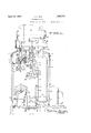
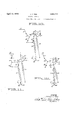
- Figure 1 is a front elevational view of apparatus incorporatin the invention, taken a ong the line 11 of ig. 2.
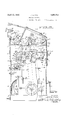
- ' Fi 2 is a side elevational view taken along the lme 2--2 of Fig. 1.
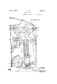
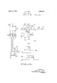
- Fig. 3 is a cross sectional view taken along the line 33 of Fig. 1.
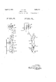
- Fig. 4 is a plan detail illustrating the manual control members and certain associated levers.
- Fig. 5 is a detail illustrating the construction'of mechanism for operating the current limiting switch.
- Fig. 9' is a detail of the mechanism shown in Flg. 8, as viewed from the right of the be incorporated latter figure.
- Figs. 10, 11 and'12 are diagrammatic views illustrating'the mode of operation of my apparatus.
- FIG. 13 is a circuit diagram illustrating the mannerin which the apparatus of this invention is incorporated with a circuit breaker.
- apparatus In order to effect successive operations of circuit devices, such as circuit breakers, apparatus has previously been devised which stores the energy of motive means in suitable sprin means. This spring means can then be re eased in stages, in order to effect successive closing and openin operations of the breaker.
- Apparatus of t is character is disclosed and claimed by the above mentioned Wilkins Patent 1,612,483. In the present invention, spring means is likewise released for porated in the present apparatus, as will be presently apparent.
- a convenient housing 11 This housing includes a suitable base portion 12, side walls 13 and 14, and front and rear walls 16 and 17
- side walls 13 and 14 can be provided with removable cover plates 18 and 19.
- this mechanism can include a rocker arm 21. Arm 21 is fixed upon a suitable shaft 22, which in turn is journaled to housing 11. The movable end of this arm 21 is connected to a rod 23, as by pivot pin 24. Rod 23 is ordinarily connected to one or more circuit breakers, so that upon rocking of arm 21, the breaker is opened or closed.
- Rod 23 is ordinarily connected to one or more circuit breakers, so that upon rocking of arm 21, the breaker is opened or closed.
- Closure39 is secured to thfe' u per end of casing 36', and slidably extende thru this closure, there is a rod 41.
- Thejlowerendiofrod'41 is connected to a piston 42, upon'wli'ich thelower ends of springs 37 and 38 areseated. The upper ends of these springs are'seated on the closure 39.
- crank46 Fig. 1 this crank being fixed to the driven s aft 27.
- a sm orifice 45 is i permit limited escape of air fromrbelow piston 42. There-.
- tow ich a fin'ger63 is-zsecured. (Figs. 1 and 2.); ;Finger163 isadapted to engage an adjustableset screw 64, carried byrbracket' 66.
- a l n xfi'f is provided which is pivotally ca' I lied .bytpin :68.”: Tl1e upper end v:offlmk carriaa a roller 60 adapted to engage overtheed 0 of a shoulder 71, formed-on plate 57. en roller'69 is in engagement'with shoul-' der 71, toggle 51 is retained in set position, in.
- toggle 51 is free to break orcollapse.
- Control of toggle 51,-thru; movement of link 67 can be either from a remote point, or by local manual means.
- links 72 and 73, link 72. ing pivotally connected to link 67 while link 3 is pivotally connected to the housing as by means of pin 74 carried by bracket 76.
- an L-lever 77 is provided, having its one arm' formed with a finger 78, underlying link 73, and its other arm'connected to a collar 79.
- Collar 7 9' is fixed to a slidable rod 80, which slidably pror jects thru wall 16 of housing 11, and is provided externally with a convenient knob. 81.
- spriiTg 82, link 73 is raised, thus moving 67, and bringin" roller 69 out of engagement with shoulder 1.
- a solenoid 84 which can also be mounted upon bracket 76. When this solenoid is energized, a plunger is projected upwardly to raise links 72 and 73.
- Toggle device 52 is preferably similar in construction to the device 51 described above.
- links 93 and 94 correspond generally to the links 53 and 54 of device 51, and are pivotally connected by pin 96.
- Link 94 is fixed with respect to a segment plate 97 and both segment plate and link 94 are journaled about a convenient shaft 98.
- Lever 94 carries a portion 103, corresponding to lever 63 of toggle device 51, which is adapted to engage an adjustable set screw 104. This set screw is carried by a bracket 106, secured to wall 61.
- a lever 107 corresponding to lever 67 of 29 device 51 is pivotally mounted u'pon shaft 108, and carries a roller 109 which can engage shoulder 111 formed on plate 97'.
- toggle device 52 In order to control operation of toggle device 52, I also prefer in this instance to provide means whereby this device can be released both manually and from a remote point.
- I. provide an arm 112, which in turn is connected'to corresponding ends of links 33 113.
- Links 113 are pivotally connected with links 114, which in turn are pivotally connect- .ed to a bracket 116.
- a solenoid 117 is arranged so that when energized, its plunger engages link 114 and raises both links 114 and 33 113, thus swinging lever 107 out of engagement with segment plates 97.
- I provide an arm 119 pivotally connected to bracket 116, by means of shaft 121.
- a lever 122 is adapted to rotate together 43 with lever 119, and has a pin and slot connection with the lower end of a rod 123.
- adjustable set screw 124 is provided in lever 119, and is adapted to engage the upper face of a stationary shelf 126.
- a counterweight 127 can depend from lever 119, in order to insure biasing of set screw 124 towards shelf 126.
- link 114 can be raised or lowered, so that when links 113 and 114 drop down to the position they assume when lever 107 is in engagement with segment I plate 97, they will move to approximately dead center position.
- the upper end of rod 123 is connected to a lever 129, which in turn is fixed to shaft 131.
- Lever 129 is adapted to rotate together with another lever 132, and this latter lever is pivotally connected to the inner end of a manual pull rod 133. As shown in Fig. 4 this rod 133 extends thru the wall 16 of the housing, adjacent to the rod 80 and is provided with a manual knob P 134.
- Preble means such as a compression spring 136, serves to normally urge rod 133 inwardly. By pulling rod 133 outwardly, it is apparent that rod 123 will be raised, thus causing rockin of lever 119, and causing lug 128 to lift lin 113 and 114, thus causing release of se ent plate 97.
- links 138 and 139 are pivotally connected to the upper end of rod 41, by means of pin 141.
- Link 139 is in turn pivotally connected to arm 142, which is carried by shaft 143.
- Links 138 are pivotally connected to a lever 144, by means of pivot pin 146, and lever 144 is fixed to shaft 22.
- Links 93 are also pivotally connected with lever 144, by means of pin 146.
- the upper end of rod 49 of spring structure 33 is pivotally connected to an arm 147, which is also carried by shaft 143, and which rotates together with arm 142.
- rocker arm 21 is in a position corresponding to open position of the breaker.
- toggle device 52 is tripped or broken, as by energizing solenoid 117, spring structure 34 acting upon arm 144 thru links 138 and 139, rotates shaft 22 to move rocker arm 21 a certain angular distance, suflicient to close the breaker.
- toggle device 51 is tripped, as by energizing solenoid 84, spring structure 33 acting upon arm 147, rotates this arm in a counterclockwise direction, thus moving arm 21 back to the position shown in Figs. 1 .to 3 inclusive.
- spring structure 34 when released by tripping toggle device 52, acts to close the'breaker, and spring structure 33 when released by tripping toggle device 51, causes subsequent opening of the breaker.
- ing 159 is carried by lever 160 and is rotatable about shaft 131, but independently of shaft 131.
- a set screw 161 carried by finger 159 is adapted to engage the face of cam 158.
- cam 158 by engaging the end of set screw 161, looks lever 160 and rod 80 connected to the same, in the positionshown in Fi 2, thus preventin an operator from mg knob 81 outwar ly to trip toggle dev1oe 52 except at the proper time.
- a suitable energizing circuit is rovidedfor motor 26. Closing of this circuit is controlled by suitable means such as a pilot switch operated by movement of the circuit breaker. or example in general practice, the pilot switch is closed upon opening of the breaker, thus clos ing the motor circuit and causing the motor to slowly rotate crank 46. Assuming that the motor is energized after both s ring structures 33 and 34, have been release and that thereafter crank 46 rotates slowly in a counterclockwise direction as viewed in Fig. 3, the first half revolution of crank pin 44, toggle device 51 is reset and spring structure 33 is restored to stressed condition. For the last half revolution of pin 44, spring structure 34 is restored to stressed condition.
- I preferably provide means for disconnecting or disrupting the motor circuit, when the pin 44 returns to its initial position.
- a conventional switch 163 for this purpose.
- This switch is mounted upon a suitable bracket 164, and has the usual movable member 166, for opening and closthe contacts thereof.
- I provide an upstanding slidable rod 167, guided by members secured to bracket 164. The upper end of rod 167 extends loosely thru a bifurcated end portion 169, of a lever 171.
- Lever 171 is journaled as by means of shaft 172, and its other end is pivotally connected to a link 173.
- link 17 3 is pivotally connected to an arm 174, carried by arm 147, and rotatable together with arms 142, 147 and 151.
- Helical spring 176 surrounds rod 167, and has its lower end seated upon lock nuts 177. The uplper end of this sprin presses against a co lar 178, which 'is slid'a ly disposed upon rod 167. Washer 179 is secured to the upper end of rod 167, and serves to engage the upper face of bifurcated portion 169.
- crank 181 Pivotally secured to bracket 164, there is a. tripping lever 181, having one ortion 182 thereof extending into the path 0 travel of a pin 183.
- Pin 183 is secured to and extends from the pin 44 of crank 46, and therefore moves in a circular path.
- the other arm 184 of lever 181 is provided with a curved cam face 186.
- the lower end of rod 167 forms a pin 187 adapted to cooperated with cam face 186.
- Cam face 186 is preferably rovided with a relatively fiat portion a, an an adjacent angular portion b.
- crank 181 is normally biased to urge cam portion a directly beneath in 187.
- Pilot switches for closing the signal circuit, and for other functions, can also be mounted within the housing 11, in lace of being associated with the circuit reaker.
- I can provide switch structures 191, 192 and 193, carried by a suitable bracket 194.
- A. rod 196 is slidably retained by bracket 194, and is connected to pin 198 on arm 144', by means of link 199.
- An adjustable collar 201 on rod 196 serves to connect this rod with the movable members of both switches 191 and 192,
- tog 'le device 51 In order to subsequently open the breaker, as for example in response to an overload, or by manually aplied force such as by pulling outwardly upon ob'81, tog 'le device 51 is tripped to permit arms 142, 14 and 151 to rotate in a counterclockwise direction, thus applying motion thru the straightened links 138 and 139, to arms 21 and 144.
- the position of the various parts after toggle device 51 has been tripped and the breaker opened, is shown in Fig. 12. It will be noted that in changing from the position shown in Fig. 11 to' that of Fig. 12, the point of application of spring structure 34 to links138 and 139 swings from left to right, this being made possible due to the fact that the lower end of spring structure 34 is pivotally connected to pin 44.
- spring structure 34 is restored to stressed con-' dition. Since winding of the spring struc tures 33 and 34 is done during difierent parts of'the movement of crank 46, it is apparent that the torque applied to the crank need only be suflicient to separately compress the springs of structures 33 and 34, thus enabling a relatively small electric motor to be employed. Furthermore in the rewindin'g operation, the power supplied from the motor is utilized efiiciently, since crank 46 is applying force to one or the other of the spring structures 33 and 34 during substantially the entire rotation of the same.
- the circuit diagram'of Fig. 13 illustrates the'manner in WhlCh the apparatus described above can be incorporated with a circuit represented at 206, associated with the power transmission lines 207.
- Overload relays 208 are associated with power transmission lines 207 g by means of the usual current transformers 209.
- the contacts of overload .relays 208 are arran ed to control a common circuit 211, which mcludes conductors 212 Y and 213.
- Switch 163 of my apparatus ineludes the contact sets 1, 2, 3 and 4, and switch 191 likewise includes the contact sets 5, 6, 7 and 8.
- Switches 192 and 193 can be connected to other circuits not shown.
- Motor 26 1s connected toone side of contacts I 1' and 3, the other sides of these contacts being connected to conductors 214 and 216.
- conductors 214 and 216 are connected to bus conductors 217 and 218, formin a convenient source of direct current.
- onductor 214 is also connected to one side of contacts 5, 6 and 8, and onductor 216 to its other terminal connected to a conductor- 224 thru a series switch 223.
- Conductor 222 connects to conductor 213, and also to bus conductor 217.
- Opening solenoid 84 has its one terminal connected to contacts 6, and its other terminal connected to conductor 212 and thus to conductor 222 thru switch 226.
- Conductor 221 connects between signal lam s 227 and 228, these lamps being in turn c nnected in series across bus conductors 217 and 218.
- switch 226 is closed, either by manual operation, or by a remote control, to energize opening solenoid 84.
- contacts 1 and 3 are closed to close the motor circuit 26, and the motor circuit is kept closed for a sufficiently long period to rewind the breaker control, after which contacts 1 and 3 are automatically opened and contacts 2 and 4 again closed.
- switch 223 is closed to energize closing solenoid 117. Energizing of opening solenoid 84 also occurs automatically-- The open condition of conno sive stages.
- mechanism ada tedto be successively actuated to effect a p urality of switching operations of an associated circuitapparatus
- energy storin means adapted to be released for successive y actuating said mechanism
- a motor and means for causing said motor to store suflicient energy to efiect said switching operations in said storing means in successiveone of said switching operations.
- mechanism ada ted to be successively actuated to efiect a p uralit'y of switching operations of an associated circuit apparatus, spring means adapted to be released after being stressed for successively actuating said mechanism, and means for stressing said spring means in stages to store suflicient energy to efiect more than 'one of saidswitching operations, said means including a member movable thru a cyclic path to effect said 5.
- .mechanism adapted to be successively actuated to efiect successive switching operations of an associated circuit apparatus, spring means adapted to be successively released for bit from an initialposition .after'complete release of spring means, and means servmemberfor stressing the spring means in ,efiecting a plurality of successive actuations ing to associate'the spring means with said" stages durin successive angular movements of said mem er.
- mechanism a apted to be successively actuated to efiect successive switching operations of an associated circuit apparatus, a plurality of springs adapted to be successively released for effecting a plurality of successlve actuations of said mechanism before either spring is restored to stressed conditions, and means for successively stressin said springs before either spring is releaseif 8.
- mechanism apted to be successively actuated to effect successive switching operations of an associated circuit apparatus a plurality .of springs-adapted to be successively released for efiecting a lurality of successive actuations of said medhanism before either spring is restored to stressed condition, and means includin a rotatable member for successively stressmg said springs before either sprin is release I 9.
- mechanism adapted to be succewively actuated to efiect successive switching operations of an associated circuit apparatus a
- an o rator of the'classdescribed, mechanism a apted to be successively actuated to efiect switching operations of an associated circuit a paratus, a .pair of springs, means including a pair of toggles for retaining said springs m st condition, means connectin said springs and said mechanism where y upon successively breaking said troggles, the mechanism is successively actuated, and means for successively stressing said springs before either spring is released.
- mechanism adapted to be successively actuated to efiect switching operations of an 11 associated circuit apparatus, a pair of springs, means including a pair of toggles for retaining said springs in stressed condition, I means connecting said springs and said mechanism whereby upon successively breakno ing said toggles the mechanism successive 1y actuated, a motor, a rotatable member driven by said motor, and means for efiecting successive stressing of said springs upon rotation of said member beforereither spring is released.
- a pair of springs an arrangement of levers to which both springs are connected, a pair of toggles associated with said levers, a rotatable member to which one spring is also connected, a relatively fixed member to which the other spring is also connected, said toggles being arranged to retain a respective spring stressed when set, a member movable in one direction upon breaking one toggle and movable in the opposite direction upon subsequent breaking of the other toggle, and means for rotating said rotatable member to efi'ect stressing of said springs, rotation of said member thru substantially 180 serving to reset a toggle and to stress one spring, and continued rotation of said member serving to stress the other spring.
- mechanism adapted to be successively actuated to efi'ect successive switching operations of an associated apparatus, a pair of spring structures adapted to be successively and independently released for efi'ecting a plurality of successive actuations of said mechanism before either spring is restared to stressed condition, and means for stressing said springs before either spring is released.
- a tripable device including a movable member having a shoulder, a lever, a roller loosely carried by said lever and adapted to engage over said shoulder, said roller when in engaged position being interposed between the opposed surfaces of a portionof said lever and of said shoulder, and a linkage mechanism connected to said lever and adapted to move the same to bring said roller out of engagement with said shoulder.
- mechanism adapted to be successively actuated to effect opening and closing of an associated circuit breaker, energy storing means adapted to be released for successively actuating said mechanism, means adapted to be actuated for effecting release of said energy storing means to efiect opening of the breaker, means adapted to be actuated for effecting release of said energy storing means to effect closing of the breaker, and interlocking means serving to preclude operation my hand.
Landscapes
- Mechanisms For Operating Contacts (AREA)
Description
April 12, 1932. c, REA 1,853,744-
BREAKER CONTROL Filed Nov. 22, 1929 7 SheetsSheet l INVENTORJ Jar/7Z5 C. Pea
A TTORNE April 12, 1932. J REA 1,853,744.
BREAKER CONTRO L ATTORNEYS.
April 12, 1932. 4
,1. c. REA
BREAKER CONTROL Filed Nov. 22, 1929 7 Sheets-Sheet 3 IN VEN TOR.
/04 Hill James C Pad April 12, 1932. J. c. REA
BREAKER CONTROL 7 Sheets-Sheet 4 I Filed Nov. 22, 1929 FIE E IN V EN TOR.
James C Bed A TTORNEYS.
J. C. REA
A ril 12', 1932.
BREAKER CONTROL 7 Sheets-Sheet 5 Filed NOV. 22, 1929 FIE E FIE E INVENTOR. James C. Pea
ATTORNEY Filed Nov. 22, 1929 7 sheets-sheet 6 FIE ll:|
' INVENTOR.
J0me5 C. E60
A TTORNEYS.
. "UNITED STATES PATENT OFFICE JAIN C. BEA,- Ol SAN FRANCISCO, CALIFORNIA, ASBIGNOR "1'0 IACII'IC ELECTRIC MANUFACTURING CORPORATION, OF SAN FRANCISCO, CALIFOBNIL,
non or camronnm- .a i umion fled November as, 1929. Serial No. 409,933.
This invention relates generally to apparams for efl'ectingo eration of e ectrical de- -vices,.as',for examp e for opening and closing breakers used in electrical power transmission systems. i g
It is an object of the present Invention to devise apparatus of the above character which ill require a relatively sm l amount. of
I ower for its operation, and which will thereore permit the use of a relatively small electrio motor. a l g It is a further ob ect of the inventlon to devise im roved apparatus of the above type characterlzed by the use of a plurality of sprin which after certain successive opera trons ave taken place, are restored to stressed condition successivelyby an electric motor or other motive means.
It is a further object of this invention to generally improve upon apparatus of the general class disclosed and-claimed by. Wilkins Patent 1,612,483.
- Further objects of the invention will appear from the following descriptiorf in which the referred embodiment of the invention has eenset forth in detail. It is to'be understood that the appended claims are to be accorded a range of equivalents consistent with the state of the prlor art. Referring to the drawings:
Figure 1 is a front elevational view of apparatus incorporatin the invention, taken a ong the line 11 of ig. 2.
' Fi 2 is a side elevational view taken along the lme 2--2 of Fig. 1.
Fig. 3 is a cross sectional view taken along the line 33 of Fig. 1.
Fig. 4 is a plan detail illustrating the manual control members and certain associated levers.
.Fig. 5 is a detail illustrating the construction'of mechanism for operating the current limiting switch.
switch, and associated tive pilot switches which may with the invention.
Fig. 9'is a detail of the mechanism shown in Flg. 8, as viewed from the right of the be incorporated latter figure.
Figs. 10, 11 and'12 are diagrammatic views illustrating'the mode of operation of my apparatus.
- Fig. 13 is a circuit diagram illustrating the mannerin which the apparatus of this invention is incorporated with a circuit breaker. In order to effect successive operations of circuit devices, such as circuit breakers, apparatus has previously been devised which stores the energy of motive means in suitable sprin means. This spring means can then be re eased in stages, in order to effect successive closing and openin operations of the breaker. Apparatus of t is character is disclosed and claimed by the above mentioned Wilkins Patent 1,612,483. In the present invention, spring means is likewise released for porated in the present apparatus, as will be presently apparent.
In the particular embodiment of the invention disclosed in the drawings, the operating parts of the apparatus are shown enclosed within a convenient housing 11. This housing includes a suitable base portion 12, side walls 13 and 14, and front and rear walls 16 and 17 For convenience side walls 13 and 14 can be provided with removable cover plates 18 and 19. for applying motion to the breaker or circuit apparatus to which my device is connected, and this mechanism can include a rocker arm 21. Arm 21 is fixed upon a suitable shaft 22, which in turn is journaled to housing 11. The movable end of this arm 21 is connected to a rod 23, as by pivot pin 24. Rod 23 is ordinarily connected to one or more circuit breakers, so that upon rocking of arm 21, the breaker is opened or closed. For the particular arrangement of parts illus- Mechanism is provided t 's 27,-thru'asuit speed reducin gearing28.,
I connected toe n -1. iiszsdapmdwto hzclutched with h fi s e e hi te ti-audit Kl lireaker is closed when rocker arm 21 is rocked in a clockwise direction, and is opened whenrocked in the opposite direction. The motive means for my apparatus is referably an electrical motor 26, which can conveniently mounted upon base portion 12, as shown in Fi 3. TlllS motor 26 is op- The details of this gearin ,however, thatthe tated, indepen' ently of motor 26. For this purpose there is ShOm i(iFi$2)i'BY Shlft 29';
3.1. Shaft 29 2s. {At same suitable motor 1s not in operation,crank-fidcanbeidperat'ed by mallilallyfrotatlng Shaft '32.
- JFFor effecting operating rncv'ementbfhf 21, energy is stored in suitable meansbyrotation ofshaiit 27-;and the stored" energy can then-be -relessedysue essively to efiect" successive movementof 21." As energystorspring structure's33 and 34; spring structure 33 is a'ssigned the function er efiecting rocking move nent -offarm 21? to "open 1 the breaker, while-s ring structure} 34 efie'cts closing. -Theses ring'. structures can somewhat similarmr construction, the structure 34'being showmin detail in'Fig. 3. In
this figure there 1s illustrated 'aLf spring vcasing 136, housing the concentric spiral compression springs-37 'and383 '"Asin is compression spripgwi 11-untion 'satis actorily,
although for reliable operation, two or more springs-are preferred. 1 Closure39 is secured to thfe' u per end of casing 36', and slidably extende thru this closure, there is a rod 41.
:Thejlowerendiofrod'41 is connected to a piston 42, upon'wli'ich thelower ends of springs 37 and 38 areseated. The upper ends of these springs are'seated on the closure 39. Member'Ae-is to the lower end of casing36,, -and;i n" the case' f spring structure 34, is pivotally connected'to a pin 44.
' 44 is carried by a crank46 Fig. 1), this crank being fixed to the driven s aft 27.
While the de'tails of spring structure 33 can be substantiallyjidentical with structure 34,, I the member secured tothe lower end of the 38 tends to move'rod 41 (in thecase of struc-' provided inmember 43 to b 'wi fiiot be ge-i e ss ss mien: rsmsnesstri able "1e meesw P "the art; Itis'preferab e shaft 27 be, ca able of being ofa 'pair of linksinovable past dead center PQsiuQQrsteer e u lize speciali devices I bistiir n L56- ihinkb-i is; formed 'as-Ta and when 'hnk 67 is moved to bring roller eeann. I
ture 34: into'casing as, sin not 42 con;
tacts with member 43. A sm orifice 45 is i permit limited escape of air fromrbelow piston 42. There-.
fore a dash-pot efiect' is roduced, tending 7 tocushion movement of r 41 andto'prevent me s ember Foriconnecting spring. and 84 m Irrsf tq iis a generally at 51 and" 52. In place of utilizing conventional toggle devices each formed so suchTas showmu nf'iivhichwdevicexliliincludesa nkl s erm: .53,-piv t 1 y to link part of a segmental plate 7, and together;
with this plateis-l'ournaled to a shaft 58. For
o r ni ncessha d581-can be supported by means oi a bar 59 extending across the houssiside W8 1 1 and; a wall 61 2 extending swr ss h int rior of the housing. Link 541.
and 2 late 57 are likewise secured to abut) 62,
tow ich a fin'ger63 is-zsecured. (Figs. 1 and 2.); ;Finger163 isadapted to engage an adjustableset screw 64, carried byrbracket' 66. I
' Set screw .64- :is normally adjusted so that links 53 and '54 can bow-moved toaelightly passed; dead center position.
- .To retain links 53 and-$54 in set position, a l n xfi'f is provided which is pivotally ca' I lied .bytpin :68.": Tl1e upper end v:offlmk carriaa a roller 60 adapted to engage overtheed 0 of a shoulder 71, formed-on plate 57. en roller'69 is in engagement'with shoul-' der 71, toggle 51 is retained in set position, in.
69 out of such engagement, toggle 51 is free to break orcollapse.
Control of toggle 51,-thru; movement of link 67, can be either from a remote point, or by local manual means. Thus I have'shown ivotally connected links 72 and 73, link 72. ing pivotally connected to link 67 ,while link 3 is pivotally connected to the housing as by means of pin 74 carried by bracket 76. To efi'ect manual operation, an L-lever 77 is provided, having its one arm' formed with a finger 78, underlying link 73, and its other arm'connected to a collar 79. Collar 7 9'is fixed to a slidable rod 80, which slidably pror jects thru wall 16 of housing 11, and is provided externally with a convenient knob. 81.
, spriiTg 82, link 73 is raised, thus moving 67, and bringin" roller 69 out of engagement with shoulder 1. To efl'ect remote control, there'is provided a solenoid 84, which can also be mounted upon bracket 76. When this solenoid is energized, a plunger is projected upwardly to raise links 72 and 73.
In order to control operation of toggle device 52, I also prefer in this instance to provide means whereby this device can be released both manually and from a remote point. Thus extending downwardly from lever 107, I.provide an arm 112, which in turn is connected'to corresponding ends of links 33 113. Links 113 are pivotally connected with links 114, which in turn are pivotally connect- .ed to a bracket 116. A solenoid 117 is arranged so that when energized, its plunger engages link 114 and raises both links 114 and 33 113, thus swinging lever 107 out of engagement with segment plates 97. To effect manual operation, I provide an arm 119 pivotally connected to bracket 116, by means of shaft 121. A lever 122 is adapted to rotate together 43 with lever 119, and has a pin and slot connection with the lower end of a rod 123. An
For associating the spring structures 33 and 34, with toggle devices 51 and 52, and rocker arm 21, I have shown means including links 138 and 139, which are pivotally connected to the upper end of rod 41, by means of pin 141. Link 139 is in turn pivotally connected to arm 142, which is carried by shaft 143. Links 138 are pivotally connected to a lever 144, by means of pivot pin 146, and lever 144 is fixed to shaft 22. Links 93 are also pivotally connected with lever 144, by means of pin 146. The upper end of rod 49 of spring structure 33, is pivotally connected to an arm 147, which is also carried by shaft 143, and which rotates together with arm 142.
The mode of operation of my apparatus will be presently explained in greater detail, by reference to Figs. 10, 11 and 12. However at this point it may be stated that in Fig. 3 both spring structures 33 and 34 are shown stressed or wound. Springstructure 34 is retained in stressed condition by toggle device 52 acting on pin 146. In order to cause toggle device 51 to retain spring structure 33 in stressed condition, anotherarm 151 is carried by shaft 143, and this armvcan also rotate together With arms 147 and 142. A pin 152 carried by arm 151, extends thru a slot 153 in the upper end of link 53. (Fig. 2.) Spring 156 is norm-ally under stress to bias link 53 upwardly relative to arm 151.
As the apparatus is illustrated' in Figs. 1, 2 and 3, rocker arm 21 is in a position corresponding to open position of the breaker. Assuming now that toggle device 52 is tripped or broken, as by energizing solenoid 117, spring structure 34 acting upon arm 144 thru links 138 and 139, rotates shaft 22 to move rocker arm 21 a certain angular distance, suflicient to close the breaker. Subsequently if toggle device 51 is tripped, as by energizing solenoid 84, spring structure 33 acting upon arm 147, rotates this arm in a counterclockwise direction, thus moving arm 21 back to the position shown in Figs. 1 .to 3 inclusive. In other words spring structure 34, when released by tripping toggle device 52, acts to close the'breaker, and spring structure 33 when released by tripping toggle device 51, causes subsequent opening of the breaker.
In order to keep the above operations in" ing 159 is carried by lever 160 and is rotatable about shaft 131, but independently of shaft 131. A set screw 161 carried by finger 159 is adapted to engage the face of cam 158. When toggle device 52 is in set position, cam 158, by engaging the end of set screw 161, looks lever 160 and rod 80 connected to the same, in the positionshown in Fi 2, thus preventin an operator from mg knob 81 outwar ly to trip toggle dev1oe 52 except at the proper time.
When my apparatus is installed, a suitable energizing circuit is rovidedfor motor 26. Closing of this circuit is controlled by suitable means such as a pilot switch operated by movement of the circuit breaker. or example in general practice, the pilot switch is closed upon opening of the breaker, thus clos ing the motor circuit and causing the motor to slowly rotate crank 46. Assuming that the motor is energized after both s ring structures 33 and 34, have been release and that thereafter crank 46 rotates slowly in a counterclockwise direction as viewed in Fig. 3, the first half revolution of crank pin 44, toggle device 51 is reset and spring structure 33 is restored to stressed condition. For the last half revolution of pin 44, spring structure 34 is restored to stressed condition.
I preferably provide means for disconnecting or disrupting the motor circuit, when the pin 44 returns to its initial position. In Fig. 5 I have shown a conventional switch 163 for this purpose. For the sake of clarit the showing of this switch has been omit from Figs. 1-3 inclusive. This switch is mounted upon a suitable bracket 164, and has the usual movable member 166, for opening and closthe contacts thereof. For operating switch 163, I provide an upstanding slidable rod 167, guided by members secured to bracket 164. The upper end of rod 167 extends loosely thru a bifurcated end portion 169, of a lever 171. Lever 171 is journaled as by means of shaft 172, and its other end is pivotally connected to a link 173. The upper end of link 17 3 is pivotally connected to an arm 174, carried by arm 147, and rotatable together with arms 142, 147 and 151. Helical spring 176 surrounds rod 167, and has its lower end seated upon lock nuts 177. The uplper end of this sprin presses against a co lar 178, which 'is slid'a ly disposed upon rod 167. Washer 179 is secured to the upper end of rod 167, and serves to engage the upper face of bifurcated portion 169.
' Pivotally secured to bracket 164, there is a. tripping lever 181, having one ortion 182 thereof extending into the path 0 travel of a pin 183. Pin 183 is secured to and extends from the pin 44 of crank 46, and therefore moves in a circular path. The other arm 184 of lever 181, is provided with a curved cam face 186. The lower end of rod 167 forms a pin 187 adapted to cooperated with cam face 186. Cam face 186 is preferably rovided with a relatively fiat portion a, an an adjacent angular portion b. By suitable means such as a. tension spring 188, crank 181 is normally biased to urge cam portion a directly beneath in 187. As has been previously explained, uring a rewinding operation, as
in 44 moves in a circular path from an inltial position and as this pin and also in 183 returns to initial position, it is desired to operate switch 163 to interrupt the motor circuit. When pin 183 has approximately returned to its initial position, it engages arm 182, thus moving lever 181 in -a counterclockwise direction, to bring cam portion a out of contact. with the lower end of pin 187. At this time the bifurcated portion 169 of lever 171 is in a lowered position, and spring 176 is compressed. The pressure of pin 187 against the inclined cam portion b causes continued movement of lever 181, to the osition shown in Fig. 5. Movement of ro 167 downwardly, operates switch 163 to disrupt the motor circuit. When the breaker is closed, by tripping toggle device 52, rod 167 still retains its same position, due to the fact that arms 142, 147 and 151 do not move. However upon subsequently o enin the breaker responsive to tripping of togg e device 51, link 173 is moved downwardly, thus raising bifurcated portion 169, and raising rod 167 until pin 187 permits tripping lever 181 to return to its initial position, with cam portion a directly below pin 187. The motor circuit is then energized and pin 183 completes another revolution, and again trips lever 181 during the completion of its circular movement.
Pilot switches for closing the signal circuit, and for other functions, can also be mounted within the housing 11, in lace of being associated with the circuit reaker. Thus as shown in Figs. 8 and 9, I can provide switch structures 191, 192 and 193, carried by a suitable bracket 194. A. rod 196, is slidably retained by bracket 194, and is connected to pin 198 on arm 144', by means of link 199. An adjustable collar 201 on rod 196, serves to connect this rod with the movable members of both switches 191 and 192,
and a similar adjustable collar 202 serves to connect rod 196 with the movable member of switch 193. It is apparent that with rocking movement of arm 21 corresponding to opena s ring structures 33 and 34 in wound condition. Both toggle devices 51 and 52 are set, read to be tripped or broken. To close the brea er, toggle 52 is tripped, thus permitting spring structure 34 to pull links 138 and 139 downwardly to rock arm 21 and close the breaker. The relationship of the parts for closed position of the breaker, is shown in Fig. 11. It will be noted that arms 142, 147 and 151, remain in the same position which they occupied in Fig. 10. In order to subsequently open the breaker, as for example in response to an overload, or by manually aplied force such as by pulling outwardly upon ob'81, tog 'le device 51 is tripped to permit arms 142, 14 and 151 to rotate in a counterclockwise direction, thus applying motion thru the straightened links 138 and 139, to arms 21 and 144. The position of the various parts after toggle device 51 has been tripped and the breaker opened, is shown in Fig. 12. It will be noted that in changing from the position shown in Fig. 11 to' that of Fig. 12, the point of application of spring structure 34 to links138 and 139 swings from left to right, this being made possible due to the fact that the lower end of spring structure 34 is pivotally connected to pin 44. Immediately after toggle 51 is collapsed and the breaker has been o ened, the motor circuit is automatically c osed, andcrank 46 commences to rotate in a counterclockwise direction as viewed in Figs. 10 to 12 inclusive, to rewind spring structures 33 and 34. As has been previously explained, during approximately the first half revolution of crank 46, or until this crank has reached the upper limit of its movement, toggle device 51 is reset, and at the same time rotation of arms 142, 147 and 151 in a clockwise direction back to the position shown in Figs. 10 and 11 restores spring structure 33 to stressed condition. During the last half revolution of crank 46 or while this crank is moving downwardly to its initial position, spring structure 33 is retained stresses due to the setting of toggle device 51, and since links 138 and 139 retain their angular relationship as shown in Fig. 10,
The circuit diagram'of Fig. 13, illustrates the'manner in WhlCh the apparatus described above can be incorporated with a circuit represented at 206, associated with the power transmission lines 207. Overload relays 208, are associated with power transmission lines 207 g by means of the usual current transformers 209. The contacts of overload .relays 208 are arran ed to control a common circuit 211, which mcludes conductors 212 Y and 213. Switch 163 of my apparatus ineludes the contact sets 1, 2, 3 and 4, and switch 191 likewise includes the contact sets 5, 6, 7 and 8. Switches 192 and 193 can be connected to other circuits not shown. Motor 26 1s connected toone side of contacts I 1' and 3, the other sides of these contacts being connected to conductors 214 and 216.
These conductors 214 and 216 are connected to bus conductors 217 and 218, formin a convenient source of direct current. onductor 214 is also connected to one side of contacts 5, 6 and 8, and onductor 216 to its other terminal connected to a conductor- 224 thru a series switch 223. Conductor 222 connects to conductor 213, and also to bus conductor 217. Opening solenoid 84 has its one terminal connected to contacts 6, and its other terminal connected to conductor 212 and thus to conductor 222 thru switch 226.-
Referring again to the diagram of Fig. 13, assuming that the breaker is closed, contacts 2 and 4 of switch 163 are closed and likewise contacts 6 and 8 of switch 191 are closed. If
the operator desires to open the breaker, switch 226 is closed, either by manual operation, or by a remote control, to energize opening solenoid 84. Upon opening of the breaker, contacts 1 and 3 are closed to close the motor circuit 26, and the motor circuit is kept closed for a sufficiently long period to rewind the breaker control, after which contacts 1 and 3 are automatically opened and contacts 2 and 4 again closed. To eflect closing of the breaker, "switch 223 is closed to energize closing solenoid 117. Energizing of opening solenoid 84 also occurs automatically-- The open condition of conno sive stages.
I claim: 1. In an operator of the character described, mechanism ada ted to be successive- 1y actuated to efiect a p urality of switching operations of an associated circuit apparatus, energy storin means adapted to be released for successive y actuating said mechanism,
and means for storing sufiicient energy to efiect said switching operations in said storing means in' distinct stages.
.2. In an operator ,of the character described, mechanism ada tedto be successively actuated to effect a p urality of switching operations of an associated circuitapparatus, energy storin means adapted to be released for successive y actuating said mechanism, a motor, and means for causing said motor to store suflicient energy to efiect said switching operations in said storing means in succesone of said switching operations.
4. In an operator of the character described, mechanism ada ted to be successively actuated to efiect a p uralit'y of switching operations of an associated circuit apparatus, spring means adapted to be released after being stressed for successively actuating said mechanism, and means for stressing said spring means in stages to store suflicient energy to efiect more than 'one of saidswitching operations, said means including a member movable thru a cyclic path to effect said 5. In an operator oft-he class described, .mechanism adapted to be successively actuated to efiect successive switching operations of an associated circuit apparatus, spring means adapted to be successively released for bit from an initialposition .after'complete release of spring means, and means servmemberfor stressing the spring means in ,efiecting a plurality of successive actuations ing to associate'the spring means with said" stages durin successive angular movements of said mem er.
7. In an o rator of the class described, mechanism a apted to be successively actuated to efiect successive switching operations of an associated circuit apparatus, a plurality of springs adapted to be successively released for effecting a plurality of successlve actuations of said mechanism before either spring is restored to stressed conditions, and means for successively stressin said springs before either spring is releaseif 8. In an 0 rator of the class described, mechanism apted to be successively actuated to effect successive switching operations of an associated circuit apparatus, a plurality .of springs-adapted to be successively released for efiecting a lurality of successive actuations of said medhanism before either spring is restored to stressed condition, and means includin a rotatable member for successively stressmg said springs before either sprin is release I 9. 11 an operator of the class described, mechanism adapted to be succewively actuated to efiect successive switching operations of an associated circuit apparatus, a
lurality of sprin adapted to be successivey released for e ectin a plurality of successive actuations of and mechanism before either spring is restored to st condition, a motor, and means connecting saidmotor and said sprin for successively said sgrings be ore either spring is release.
10. n an o rator of the'classdescribed, mechanism a apted to be successively actuated to efiect switching operations of an associated circuit a paratus, a .pair of springs, means including a pair of toggles for retaining said springs m st condition, means connectin said springs and said mechanism where y upon successively breaking said troggles, the mechanism is successively actuated, and means for successively stressing said springs before either spring is released. 1
11. In an operator of the class described, mechanism adapted to be successively actuated to efiect switching operations of an 11 associated circuit apparatus, a pair of springs, means including a pair of toggles for retaining said springs in stressed condition, I means connecting said springs and said mechanism whereby upon successively breakno ing said toggles the mechanism successive 1y actuated, a motor, a rotatable member driven by said motor, and means for efiecting successive stressing of said springs upon rotation of said member beforereither spring is released.
12.; In an o erator' ofthe described, mechanism a apted; V to successively I actuated-to efiect switching operations of an associated circuit apparatus, a pair of 1 springs, means including a pair of toggles for retaining said springs in stressed condition, means connecting said springs and said mechanism whereby upon successively breaking said toggles the mechanism is -successively actuated, a motor, a member driven by the motor thru an angle of substantially 360 for a rewinding operation, and means associating said springs and the motor for eifecting stressing of one spring during the initial angular movement of said member and for stressing the other spring during final angular movement of said member.
13. In a breaker operator of the class described, a pair of springs, an arrangement of levers to which both springs are connected, a pair of toggles associated with said levers, a rotatable member to which one spring is also connected, a relatively fixed member to which the other spring is also connected, said toggles being arranged to retain a respective spring stressed when set, a member movable in one direction upon breaking one toggle and movable in the opposite direction upon subsequent breaking of the other toggle, and means for rotating said rotatable member to efi'ect stressing of said springs, rotation of said member thru substantially 180 serving to reset a toggle and to stress one spring, and continued rotation of said member serving to stress the other spring.
14. In an operator of the class described, mechanism adapted to be successively actuated to efi'ect successive switching operations of an associated apparatus, a pair of spring structures adapted to be successively and independently released for efi'ecting a plurality of successive actuations of said mechanism before either spring is restared to stressed condition, and means for stressing said springs before either spring is released.
15. In an operator of the class described, a tripable device including a movable member having a shoulder, a lever, a roller loosely carried by said lever and adapted to engage over said shoulder, said roller when in engaged position being interposed between the opposed surfaces of a portionof said lever and of said shoulder, and a linkage mechanism connected to said lever and adapted to move the same to bring said roller out of engagement with said shoulder.
16. In an operator of the character described, mechanism adapted to be successively actuated to effect opening and closing of an associated circuit breaker, energy storing means adapted to be released for successively actuating said mechanism, means adapted to be actuated for effecting release of said energy storing means to efiect opening of the breaker, means adapted to be actuated for effecting release of said energy storing means to effect closing of the breaker, and interlocking means serving to preclude operation my hand.
JAMES C. REA.
Priority Applications (1)
| Application Number | Priority Date | Filing Date | Title |
|---|---|---|---|
| US409033A US1853744A (en) | 1929-11-22 | 1929-11-22 | Breaker control |
Applications Claiming Priority (1)
| Application Number | Priority Date | Filing Date | Title |
|---|---|---|---|
| US409033A US1853744A (en) | 1929-11-22 | 1929-11-22 | Breaker control |
Publications (1)
| Publication Number | Publication Date |
|---|---|
| US1853744A true US1853744A (en) | 1932-04-12 |
Family
ID=23618776
Family Applications (1)
| Application Number | Title | Priority Date | Filing Date |
|---|---|---|---|
| US409033A Expired - Lifetime US1853744A (en) | 1929-11-22 | 1929-11-22 | Breaker control |
Country Status (1)
| Country | Link |
|---|---|
| US (1) | US1853744A (en) |
Cited By (1)
| Publication number | Priority date | Publication date | Assignee | Title |
|---|---|---|---|---|
| US3072763A (en) * | 1960-02-15 | 1963-01-08 | Allis Chalmers Mfg Co | Spring actuated contact opening and closing mechanism |
-
1929
- 1929-11-22 US US409033A patent/US1853744A/en not_active Expired - Lifetime
Cited By (1)
| Publication number | Priority date | Publication date | Assignee | Title |
|---|---|---|---|---|
| US3072763A (en) * | 1960-02-15 | 1963-01-08 | Allis Chalmers Mfg Co | Spring actuated contact opening and closing mechanism |
Similar Documents
| Publication | Publication Date | Title |
|---|---|---|
| US2581181A (en) | Heavy-duty air circuit breaker | |
| US2311714A (en) | Reclosing circuit breaker | |
| US1853744A (en) | Breaker control | |
| US2334571A (en) | Circuit protective switch | |
| US3198906A (en) | Circuit breaker with stored energy operating mechanism | |
| US2298143A (en) | Reclosing circuit interrupter | |
| US2769874A (en) | Closing mechanism for an electric circuit breaker | |
| US2295308A (en) | High speed reclosing mechanism | |
| US2804521A (en) | Circuit interrupter | |
| US2476076A (en) | Automatic polyphase reclosing circuit breaker | |
| US2671141A (en) | Switch operating means | |
| US2269604A (en) | Circuit breaker operating mechanism | |
| US2334339A (en) | Electric switch system | |
| US1853745A (en) | Circuit breaker operator | |
| US2282007A (en) | Control of motor operated devices | |
| US2156072A (en) | Operating mechanism | |
| US1791446A (en) | Electric switching device | |
| US3174022A (en) | Circuit breaker having stored energy operating mechanism employing a pair of overcenter toggles | |
| US2570153A (en) | Reclosing mechanism for circuit breakers | |
| US2456971A (en) | Circuit breaker | |
| US2258195A (en) | Circuit breaker mechanism | |
| US1841162A (en) | Switch operating mechanism | |
| US3251963A (en) | Repeating circuit interrupter | |
| US1902476A (en) | Circuit controlling apparatus | |
| US1318784A (en) | Circuit-interrupter |