US1853737A - Power transmitting mechanism for lathes or the like - Google Patents
Power transmitting mechanism for lathes or the like Download PDFInfo
- Publication number
- US1853737A US1853737A US484756A US48475630A US1853737A US 1853737 A US1853737 A US 1853737A US 484756 A US484756 A US 484756A US 48475630 A US48475630 A US 48475630A US 1853737 A US1853737 A US 1853737A
- Authority
- US
- United States
- Prior art keywords
- roller
- rollers
- driven
- ring
- driving
- Prior art date
- Legal status (The legal status is an assumption and is not a legal conclusion. Google has not performed a legal analysis and makes no representation as to the accuracy of the status listed.)
- Expired - Lifetime
Links
- 230000007246 mechanism Effects 0.000 title description 10
- 230000008859 change Effects 0.000 description 11
- 238000010276 construction Methods 0.000 description 5
- 230000009471 action Effects 0.000 description 3
- 230000001627 detrimental effect Effects 0.000 description 2
- 230000000694 effects Effects 0.000 description 2
- 230000009467 reduction Effects 0.000 description 2
- 101000633680 Homo sapiens Tetratricopeptide repeat protein 37 Proteins 0.000 description 1
- 101100203658 Mus musculus Spag1 gene Proteins 0.000 description 1
- 229910000831 Steel Inorganic materials 0.000 description 1
- 102100029210 Tetratricopeptide repeat protein 37 Human genes 0.000 description 1
- 230000001133 acceleration Effects 0.000 description 1
- 230000000295 complement effect Effects 0.000 description 1
- 150000001875 compounds Chemical class 0.000 description 1
- 230000003111 delayed effect Effects 0.000 description 1
- 238000004519 manufacturing process Methods 0.000 description 1
- QXLPXWSKPNOQLE-UHFFFAOYSA-N methylpentynol Chemical compound CCC(C)(O)C#C QXLPXWSKPNOQLE-UHFFFAOYSA-N 0.000 description 1
- 238000003801 milling Methods 0.000 description 1
- 230000004048 modification Effects 0.000 description 1
- 238000012986 modification Methods 0.000 description 1
- 230000004044 response Effects 0.000 description 1
- 125000006850 spacer group Chemical group 0.000 description 1
- 239000010959 steel Substances 0.000 description 1
- 208000007004 trichohepatoenteric syndrome Diseases 0.000 description 1
Images
Classifications
-
- B—PERFORMING OPERATIONS; TRANSPORTING
- B23—MACHINE TOOLS; METAL-WORKING NOT OTHERWISE PROVIDED FOR
- B23B—TURNING; BORING
- B23B3/00—General-purpose turning-machines or devices, e.g. centre lathes with feed rod and lead screw; Sets of turning-machines
- B23B3/04—Turning-machines in which the workpiece is rotated by means at a distance from the headstock
-
- Y—GENERAL TAGGING OF NEW TECHNOLOGICAL DEVELOPMENTS; GENERAL TAGGING OF CROSS-SECTIONAL TECHNOLOGIES SPANNING OVER SEVERAL SECTIONS OF THE IPC; TECHNICAL SUBJECTS COVERED BY FORMER USPC CROSS-REFERENCE ART COLLECTIONS [XRACs] AND DIGESTS
- Y10—TECHNICAL SUBJECTS COVERED BY FORMER USPC
- Y10T—TECHNICAL SUBJECTS COVERED BY FORMER US CLASSIFICATION
- Y10T82/00—Turning
- Y10T82/25—Lathe
- Y10T82/2552—Headstock
- Y10T82/2554—Speed changing gear
Definitions
- lathe is representative of machines'of this general class. With apparatus of this charj acter even a slight variation in the operating speed may produce quite a noticeable effect on a product, as for instance a variation in the smoothness or in the depth of a cut being made by a lathe.
- Such an arrangement greatly increases the utility of a machine by making the higher speeds available through the detachable unit and the normal range of speeds available directly from the machine Without the necessity of altering the construction of such a machine.
- cutting toolsV for lathes7 such as a tool with a carboloy tip for example, are available which will stand up at speeds at least as high as 3000 l. P. M. l'nasmuch as the lathe builders have been unable to produce a geared lathe which will operate satisfactorily at a speed above approximately 1200 R. P. M. the limit set by the selective gearing, it has been impossible to obtain anywhere near the maximum cutting value from such tools and of course the utility and productive capacity Yofmachines of this type have remained limited accordingly.
- the invention relates to power transmitting mechanism for transmitting'power at substantially uniform speeds without objectionable variations during changes of load or during accelerations or decelerations of the particular machine with which this mechanism may be employed.
- the power transmitting means maybe embodied ina machine for. transmitting powerdirectly from a power shaft or. from a prime mover to the work to be treated.
- the power transmitting mechanism is in the form of detachable unit adaptedto s be connected to machines ofthis class for vincreasing thek utility thereof without the' necessity of altering the design or present construction.
- Objects4 of the present invention are to y improve the efficiency of apparatus of the class described by providing means for increasing the operating speeds thereof beyond the range of speeds obtainable with geared units.; to provide apparatus of the Vclass described withmeans for transmitting or delivering power evenly and smoothly ata substantially uniform rate, either at con-vV stant speeds or vduring changes of speeds as well as under constant or'variable loads; to provide a detachable unit embodying Vpower transmitting mechanism ⁇ of this kind which is also compactly arranged and economical of space; and also to provide an improved unit -of this character of rugged,
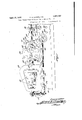
- Fig. ll is a side elevation of a portion of a llathe with parts broken away to showde- ⁇ rails of the construction; i l
- Fig. 3 is a central horizontal section of the speed change apparatus shown in Figs. 1 and 2;
- Figs. 4 and 5 are diagrammatic views of speed change apparatus.
- a lathe comprising a bed 10 having ways 11 and 12 which slidably support the carriage 13 in-the usual manner.
- a compound tool rest 14 is mounted upon this carriage and carries a tool holder 16 which receives a tool 17.
- the Vhead stock 18 is mounted on the bed 10 and provides bearings for the spindle 19 which is adapted to be driven by the stepped pulleys 21.
- the spindle is also connected by suitable gearing 22 to the lead screw 23, the latter being mounted in a bearing 24 carried by the bed and operatively connected to the carriage 13 in the manner well understood in this art.
- a speed change mechanism indicated generally at 26. is detachably connected to the nose of the spindle 19 and carries the usual face plate 27
- a piece of stock 28 is also illus- 'trated as mounted on the center 29 and is rotated by means of a dog 31 which engages one of the slots or other openings 32 in the face plate.
- the carriage 13 is also equipped with a hand wheel 33 for manual feed and with controls 34 and 36 for the usual automatic feeds.
- the vcompound tool rest islilre- Wise provided with manually operable handles 37 and 38 for adjusting the position of the tool and is otherwise ofthe usual construction.
- the power transmitting or speed change mechanism 26 is shown more clearly in Figs. 2 'and 3 from which it will be seen that this apparatus comprises a. casing 39 which provides a frame for supporting the operating parts thereof. This casing is provided with feet, not shown, which are secured on the ways 11 and 12 by a clamping plate 40 Vattached to the housing and extending under the ways to support this apparatus as indicated in Fig. 1.
- a. primary driving roller 41 is rigidly secured to or tat'ably mounted at either side ofthe roll, preferably in anti-friction bearings such as ball bearings 43 and 44. This shaft is Vheld in properly spaced relation in these bearings by spacers 46 and 47 threaded thereon.
- ⁇ recess 'or chamber 48 which receives the larger 'bearing 43 preferably extends voutwardly to the outside of the casing 39 so that this bearing may readily be inserted in its proper position.
- the chamber 48 is closed by removable cover 49 which fits over the end of the shaft 42 and carries a felt or other suitable oil retaining ring 51. This end of the sha-ft 42 is slotted transversely, as indicated at 52,
- auxiliary nose cap 54 This nose cap is threaded onto the nose and spindle 19 and provides a convenient and eective means for connecting this spin- Y die to the power transmitting mechanism.
- An idler roller 56 is rotatably mounted in bearings 57 and 56 atone side of the primary roller 41 to engage the latter.
- the bearings 57 and 58 are disposed in suitable recesses 59 and 61 formed in the casing 39, the recess 61 being closed by a removable cover 62.
- a lay shaft 63 is disposed preferably at the opposite side of the primary driving roller 41 and carries a driven roller 64 arranged to engage the driving roller 41 and also a secondary driving roller 66.
- a resilient annulus or ring 65 is disposed about the driven roller 64 and the idler roller 56 and is of such a size as to have its inner periphery firmly lengage the rollers 56v and 64 thus to tend to press these rollers against the vinterposed driving roller 41 so as to ensure good adhesion between the Vengaginggg surfaces of these rollers.
- This lay' shaft rotatably mounted in bearings 67, 68 mounted respectively in recesses or chambers 69, 7 0, each of which is closed by a removable cover 71 and 72 respectively.
- An idler roller 73 is rotatably mounted in bearings 74, 76 in position to engage the secondary driving roller 66.
- Bearings 74 and 7 6 are mounted in chambers 77, 78 formed in the casing 39, the c hamber 7 8 being closed by a removable cover r9.
- a driven shaft 81 is arranged with its axis in alignment with the axis of the driving shaft 42 and carries a secondary driven roller 82 disposed ,in engagement with the secondary driving roller 66.
- a resilient anni-ilus or ring 85 is disposed about and in snug 'engagement with the peripheries of the .idler roller 73 and driven roller 82 so as to press these rollers aga-inst the secondary roller 66 and thus to ensure good adhesion ⁇ between the contacting surfaces of these members.
- One end of the shaft 81 is mounted inthe ball bearing 83 while at the opposite side of the roller 82 the shaft is tapered and is rotatably supported in a tapered bearing 84.
- the outer end or nose of 'the shaft 81 threaded, as indicated at 86, to receive the face plate 27.
- FIG. 5 Another arrangement of driving, driven and idler rollers is shown diagrammatically in Fig. 5.
- the driving roller 91 is arranged directly to engage the resilient ring 92 which latter also engages the idler roller 93, the driven roller 94 being disposed between the idler and the Vdriving roller.
- the driving roller 91 is arranged directly to engage the resilient ring 92 which latter also engages the idler roller 93, the driven roller 94 being disposed between the idler and the Vdriving roller.
- an arrangement of rollers such as that shown in Fig. 5 may be embodied in an apparatus of the class described, it is preferred to use the arrangement shown in Figs. l and 4 for reasons which will presently appear.
- a machine of the class described having a spindle and a speedchange power transmitting unit said unit comprising a housing, two sets of rolls within and supported by the housing, each of said sets of rolls having an intermediate driving roll, a driven roll in frictional engagement with the driving roll, an idler roll opposite to the driven roll and in frictional engagement with the driving roll and an annular ring associated with each set of rolls and frictionally engaging the corresponding driven roll and idler roll, the driving roll of the first of said sets being mounted in axial alignment with said spindle, and a shaft supporting said last-named driving roll and detachably ⁇ connecting the same to the spindle, an aligned shaft supporting the driven roll of said second set, a common shaft supporting the driven roll of the first set and the driving roll of the second set, each of said annular rings being normally in symmetric relation with the corresponding driving roll of its set, but being movable into a slightly unsymmetric relation thereto in response to tendency toward slippage between the driving and driven rolls of the
Landscapes
- Engineering & Computer Science (AREA)
- Mechanical Engineering (AREA)
- Friction Gearing (AREA)
Description
April 12, 1932. E. R. L LEWELLYN POWER TEANSMITTING 'MECHANISM EOE LATHEs 0R THE LIKE Filed Sept. 27, 1950 3 Sheets-Sheet l NN oo EN .NN
Apri112,1932. -E R. LLEWELLQN 1,853,737
POWER TRANSMITTING MECHANISM FOR LATHES OR THE LIKE Filegi Sept. 27, 193() I5 Sheets-Sheet 2 f gill we April l2, 1932. E, R, L LEWELLYN POWER TRANSMITTING MECHANISM FOR LATHES OR THE LIKE Filed Sept. 27, 1930 5 Sheets-Sheet 3 `range vof operating speeds.
Patented Apr. 12, 1932 v entre; strates OFFCE, f
ERNEST R. LLEWELLYN, OF ARLINGTON, MASSACHUSETTS; ASSIGNOR lT0 THE HENDEY MACHINE COMPAJVY, OF TORRINGTON, CNNECTICUT, A CORPvORAlON 0F CON- NECTCUT POWER TBANSMTTIGG IECHANSM FR LA THES OB, THE LIKE Application filed September 27, 1930. Seral'No. 484,756.
as relatively high speeds are desirable. fr
lathe is representative of machines'of this general class. With apparatus of this charj acter even a slight variation in the operating speed may produce quite a noticeable effect on a product, as for instance a variation in the smoothness or in the depth of a cut being made by a lathe.
It is customary to equip machinesof this f class with gearing, usually of the selective change speed type, for obtaining the desired However, the maximum permissible operating speed for a geared unit is about 1200 R. M. Above this speed the gears are not only too noisy and unsafe, but also produceexcessive chat,- ter marks in the work due to tooth impact at high velocity. For these reasons a detachable unit of the type embodying toothed reduction gearing can not be modified merely by changing the ratios to provide a satisfactory speed increaser unit. tpis highly desirable that a machine of this type be capable of operating at much higher speeds and that these speeds be attainable with a detachable speed increaser unit. Such an arrangement greatly increases the utility of a machine by making the higher speeds available through the detachable unit and the normal range of speeds available directly from the machine Without the necessity of altering the construction of such a machine. At the present time cutting toolsV for lathes7 such as a tool with a carboloy tip for example, are available which will stand up at speeds at least as high as 3000 l. P. M. l'nasmuch as the lathe builders have been unable to produce a geared lathe which will operate satisfactorily at a speed above approximately 1200 R. P. M. the limit set by the selective gearing, it has been impossible to obtain anywhere near the maximum cutting value from such tools and of course the utility and productive capacity Yofmachines of this type have remained limited accordingly.
' Some aspects of the present invention rei 'late to means for increasing the roperating speeds of machines of the class referred to beyondr the range/of speeds obtainable with geared units. In other aspects the invention relates to power transmitting mechanism for transmitting'power at substantially uniform speeds without objectionable variations during changes of load or during accelerations or decelerations of the particular machine with which this mechanism may be employed. In this aspect the power transmitting means maybe embodied ina machine for. transmitting powerdirectly from a power shaft or. from a prime mover to the work to be treated. vln some preferred embodiments, however, the power transmitting mechanism is in the form of detachable unit adaptedto s be connected to machines ofthis class for vincreasing thek utility thereof without the' necessity of altering the design or present construction.
Objects4 of the present invention are to y improve the efficiency of apparatus of the class described by providing means for increasing the operating speeds thereof beyond the range of speeds obtainable with geared units.; to provide apparatus of the Vclass described withmeans for transmitting or delivering power evenly and smoothly ata substantially uniform rate, either at con-vV stant speeds or vduring changes of speeds as well as under constant or'variable loads; to provide a detachable unit embodying Vpower transmitting mechanism` of this kind which is also compactly arranged and economical of space; and also to provide an improved unit -of this character of rugged,
durable and yet sensitive construction capable of responding to slight changes in operating conditions and consisting of a few parts which are relatively simple and inexpensive to manufacture. f
In the drawings;
Fig. ll is a side elevation of a portion of a llathe with parts broken away to showde- `rails of the construction; i l
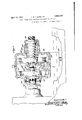
' formed integral with a shaft 42 which is ro- Fig. 2 is a central vertical section of speed change apparatus shown in Fig. 1;
Fig. 3 is a central horizontal section of the speed change apparatus shown in Figs. 1 and 2; and
Figs. 4 and 5 are diagrammatic views of speed change apparatus.
For the purposes of illustration the features of the invention have been shown in the drawings as embodied in a lathe comprising a bed 10 having ways 11 and 12 which slidably support the carriage 13 in-the usual manner. A compound tool rest 14 is mounted upon this carriage and carries a tool holder 16 which receives a tool 17. The Vhead stock 18 is mounted on the bed 10 and provides bearings for the spindle 19 which is adapted to be driven by the stepped pulleys 21. The spindle is also connected by suitable gearing 22 to the lead screw 23, the latter being mounted in a bearing 24 carried by the bed and operatively connected to the carriage 13 in the manner well understood in this art.
. A speed change mechanism, indicated generally at 26. is detachably connected to the nose of the spindle 19 and carries the usual face plate 27 A piece of stock 28 is also illus- 'trated as mounted on the center 29 and is rotated by means of a dog 31 which engages one of the slots or other openings 32 in the face plate. The carriage 13 is also equipped with a hand wheel 33 for manual feed and with controls 34 and 36 for the usual automatic feeds. The vcompound tool rest islilre- Wise provided with manually operable handles 37 and 38 for adjusting the position of the tool and is otherwise ofthe usual construction.
The power transmitting or speed change mechanism 26 is shown more clearly in Figs. 2 'and 3 from which it will be seen that this apparatus comprises a. casing 39 which provides a frame for supporting the operating parts thereof. This casing is provided with feet, not shown, which are secured on the ways 11 and 12 by a clamping plate 40 Vattached to the housing and extending under the ways to support this apparatus as indicated in Fig. 1. Within the casing a. primary driving roller 41 is rigidly secured to or tat'ably mounted at either side ofthe roll, preferably in anti-friction bearings such as ball bearings 43 and 44. This shaft is Vheld in properly spaced relation in these bearings by spacers 46 and 47 threaded thereon. The
` recess 'or chamber 48 which receives the larger 'bearing 43 preferably extends voutwardly to the outside of the casing 39 so that this bearing may readily be inserted in its proper position. The chamber 48 is closed by removable cover 49 which fits over the end of the shaft 42 and carries a felt or other suitable oil retaining ring 51. This end of the sha-ft 42 is slotted transversely, as indicated at 52,
to receive a complementary abutment or transverse rib 53 formed on an auxiliary nose cap 54. This nose cap is threaded onto the nose and spindle 19 and provides a convenient and eective means for connecting this spin- Y die to the power transmitting mechanism.
An idler roller 56 is rotatably mounted in bearings 57 and 56 atone side of the primary roller 41 to engage the latter. The bearings 57 and 58 are disposed in suitable recesses 59 and 61 formed in the casing 39, the recess 61 being closed by a removable cover 62. A lay shaft 63 is disposed preferably at the opposite side of the primary driving roller 41 and carries a driven roller 64 arranged to engage the driving roller 41 and also a secondary driving roller 66. A resilient annulus or ring 65 is disposed about the driven roller 64 and the idler roller 56 and is of such a size as to have its inner periphery firmly lengage the rollers 56v and 64 thus to tend to press these rollers against the vinterposed driving roller 41 so as to ensure good adhesion between the Vengaginggg surfaces of these rollers. This lay' shaft rotatably mounted in bearings 67, 68 mounted respectively in recesses or chambers 69, 7 0, each of which is closed by a removable cover 71 and 72 respectively. An idler roller 73 is rotatably mounted in bearings 74, 76 in position to engage the secondary driving roller 66. Bearings 74 and 7 6 are mounted in chambers 77, 78 formed in the casing 39, the c hamber 7 8 being closed by a removable cover r9.
A driven shaft 81 is arranged with its axis in alignment with the axis of the driving shaft 42 and carries a secondary driven roller 82 disposed ,in engagement with the secondary driving roller 66. A resilient anni-ilus or ring 85 is disposed about and in snug 'engagement with the peripheries of the .idler roller 73 and driven roller 82 so as to press these rollers aga-inst the secondary roller 66 and thus to ensure good adhesion `between the contacting surfaces of these members.
One end of the shaft 81 is mounted inthe ball bearing 83 while at the opposite side of the roller 82 the shaft is tapered and is rotatably supported in a tapered bearing 84. The outer end or nose of 'the shaft 81 threaded, as indicated at 86, to receive the face plate 27.
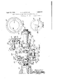
The manner in which the various driving, driven and idler rollers function Ais sho-Wn more clearly in Fig. 4 in whichfor the purposes yof illustration the central rollermay Je regarded as the primary drivin-g roll 41. while one of the smaller rollers represents the driven roll 64, and the other small roller indicates the idler roller 56. The ring 65 is -also illustrated as in engagement with rthe rollers 64 and A56. These rollers well `as the ring 65 preferably are formed with hard Yground steel surfacesA which roll lupon each other and which are pressed together with 'forces depending` largely upon they position of the ring 65. As thefroller 41 is operated a uniform rate and for relatively light loads,
this relationship is preserved. -However, as soon as the driving roller 4l tends to slip due to lack of adhesion with the driven roller 64 this results in an increase in speed of the roller 56 which, due to its engagement with the ring 65, moves the latter upwardly, thereby moving the center or axis of the ring 65 out of alignment with the axes ofthe rollers and thus causing the-ring toV assume some position such as that shown in the dotted lines. It will be apparent thatv when the ring is in this position it -will exert a greater pressure on the outer rollers 56 and 64 and produce greater adhesion between these rollers and the driving roller 4l. Inthis way the ring 65 functions to counteract any tendency'fo-r slipping betweenthe various-rollers.V
t will be understoodthat as the ring exerts a greater binding force on the rollers 56 and 64 the latter must yield or move to some relatively slight extent in order to obtain the increased adhesion. In some cases this is pro-vided for by mounting one of the rollers in movable bearings, usually the idler roller,
. while in other cases the bearings themselves may be sufficiently compressible to allow this slight change, or the roller may be the compressible or slightly yieldable member. As these features of this apparatus are well understood in the art, they are only briefly referred to here.
Another arrangement of driving, driven and idler rollers is shown diagrammatically in Fig. 5. In this view the driving roller 91 is arranged directly to engage the resilient ring 92 which latter also engages the idler roller 93, the driven roller 94 being disposed between the idler and the Vdriving roller. fhile it is contemplated that in some instances an arrangement of rollers such as that shown in Fig. 5 may be embodied in an apparatus of the class described, it is preferred to use the arrangement shown in Figs. l and 4 for reasons which will presently appear.
As previously pointed out, there are many classes of work commonly performed on lathes, boring mills, milling machines and related apparatus in which a slight variation in the operating speed is detrimental tothe work produced. Where such precision and accuracy isrequired the arrangement of rollers shown in Figs. l to 4 of the drawings should be employed. For instance, assume that power is being transmitted through apparatus such as that shown in Fig. 5 and that for some reason there isa slight tendency for the driving roller 91 to slip on the driven roller 94. In the practically infinitesimal interval of time during which any tendency to slip first exhibits itself, the factors of adhesion between each pair of contacting-rollers and also between the rollers and the ring are substantially the same. To correct this condition so as to prevent slipping, it is necessary for the ring to move (clockwise as shown) faster than the idler 93. The resulting increase in speedof the ring tends to accelerate the idler in the same proportion, thev latter slipping on the driven roller momentarily. VVhenthis occurs the axis of the ring 280 does not change its position promptly and L consequently the requisite adhesion for the greater loads is not provided without momentary delay. This delay is usually sufficient to cause damage to work being done. l/Vhile the effect of this delayed action of the ring on the low speed member of a speed reduction set is relatively slight, it is nevertheless objectionable for apparatus of the class described. On speed increaser units, however, and particularly on such units as are intended for use on lathes and related apparatus, thisdelayed action produces a much more pronounced and decidedly objectionable` affect Von the high speed member, which on a lathe operatesl the face plate and rotates the stock. V
These undesirable results are avoided by employing apparatus of thetype shown in i retarded) asa pivot.v This action is pracl 'tically instantaneous with the result that the ring is moved to a position to prevent slipping before any detrimental change of speed of the driven roller can take place. This arrangement is therefore much more-sensitive ithan that shownin Fig. 5 and its use avoids Aobjectionable results of thetype justv pointed out. Y Furthermore, yit will be seen that the productive capacity and utility of a machine of Fl Athe class described may be increased by the use of a speed change unit, such as the illustratedspeed increaser unit and that this may be accomplished without the use of tooth gearing, and yet with the lassurance of a smooth,-l
even flow ofv power under various operating conditions. For instance,'a lathe equipped l withV such a speed increaser isv capable of rotating a piece of stock at 3000 or Vmore "R. P. M., as desired, without producing the 5130 objectionable variations in speed, which have heretofore made it impractical to attempt to operate at this relatively high speed. t thus becomes possible to obtain the maximum cutting value from the better grade of cutting tools and in general to increase the operating eiiiciency of machines of this class. As the speed change unit is readily detachable, the usual range of lower operating speeds becomes available upon removal of theunit, in which event the face plate is attached directly to the spindle in the usual manner.
It should be understood that the present disclosure is for the purpose of illustration only and that this invention includes all modifications and equivalents which fall within the scope of the appended claims.
l. `The combination of a machine of the class described having a spindle and a speedchange power transmitting unit, said unit comprising a housing, two sets of rolls within and supported by the housing, each of said sets of rolls having an intermediate driving roll, a driven roll in frictional engagement with the driving roll, an idler roll opposite to the driven roll and in frictional engagement with the driving roll and an annular ring associated with each set of rolls and frictionally engaging the corresponding driven roll and idler roll, the driving roll of the first of said sets being mounted in axial alignment with said spindle, and a shaft supporting said last-named driving roll and detachably `connecting the same to the spindle, an aligned shaft supporting the driven roll of said second set, a common shaft supporting the driven roll of the first set and the driving roll of the second set, each of said annular rings being normally in symmetric relation with the corresponding driving roll of its set, but being movable into a slightly unsymmetric relation thereto in response to tendency toward slippage between the driving and driven rolls of the set whereby the frictional engagement of said rolls is automatically increased, and whereby a frictional drive adapted effectively to operate at high speeds is afforded.
2. The combination with a machine of the class described comprising axially aligned driving and driven shaft sections, of a speed increaser unit interposed therebetween, said unit comprising a plurality of sets of toothless friction rollers, a lay shaft extending between the rollers of each set, the lay shaft being offset to one side of said aligned shaft sections, one of said sets of rollers comprising a driving roller connected to said driving shaft section, an idler on one side of this driving roller` and in frictional contact therewith, a driven roll-er on the other side of this driving roller and in frictional contact therewith, this driven roller being carried by the lay shaft, these rollers havingtheir axes disposed normal-ly in a single plane but movable out of this plane for increasing adhesion, an annulus having a smooth continuous and uninterrupted innersurface in frictional contact with idler and driven rollers of this A set, this annulus being automatically 4movable transversely of the axes of these rollers for forcing the latter together to increase the adhesion therebetween, the next set of rollers comprising a driving kroller carried by said lay shaft, an idler roller and a driven roller disposed on opposite sides of the latter driving roller and in frictional contact therewith, the latter driven roller being connected to said driven shaft section, the rollers of this set also having their aXes disposed normally in a singleplane but movable out of this plane for increasing adhesion, and an annulus hav- `ing a smooth continuous and uninterrupted inner surface 1n frictional contact with the
Priority Applications (1)
| Application Number | Priority Date | Filing Date | Title |
|---|---|---|---|
| US484756A US1853737A (en) | 1930-09-27 | 1930-09-27 | Power transmitting mechanism for lathes or the like |
Applications Claiming Priority (1)
| Application Number | Priority Date | Filing Date | Title |
|---|---|---|---|
| US484756A US1853737A (en) | 1930-09-27 | 1930-09-27 | Power transmitting mechanism for lathes or the like |
Publications (1)
| Publication Number | Publication Date |
|---|---|
| US1853737A true US1853737A (en) | 1932-04-12 |
Family
ID=23925476
Family Applications (1)
| Application Number | Title | Priority Date | Filing Date |
|---|---|---|---|
| US484756A Expired - Lifetime US1853737A (en) | 1930-09-27 | 1930-09-27 | Power transmitting mechanism for lathes or the like |
Country Status (1)
| Country | Link |
|---|---|
| US (1) | US1853737A (en) |
Cited By (2)
| Publication number | Priority date | Publication date | Assignee | Title |
|---|---|---|---|---|
| US2456755A (en) * | 1947-01-31 | 1948-12-21 | Claude J Terrell | Helical coil butt ground winding machine |
| US3364760A (en) * | 1965-02-23 | 1968-01-23 | Kendick Mfg Company Inc | Anti-backlash frictional drive |
-
1930
- 1930-09-27 US US484756A patent/US1853737A/en not_active Expired - Lifetime
Cited By (2)
| Publication number | Priority date | Publication date | Assignee | Title |
|---|---|---|---|---|
| US2456755A (en) * | 1947-01-31 | 1948-12-21 | Claude J Terrell | Helical coil butt ground winding machine |
| US3364760A (en) * | 1965-02-23 | 1968-01-23 | Kendick Mfg Company Inc | Anti-backlash frictional drive |
Similar Documents
| Publication | Publication Date | Title |
|---|---|---|
| US1853737A (en) | Power transmitting mechanism for lathes or the like | |
| US1704205A (en) | Journal mechanism | |
| US2182012A (en) | Spindle | |
| US2014679A (en) | Reaming apparatus | |
| US3762231A (en) | Variable diameter pulley | |
| US2297078A (en) | Drill press | |
| US4085630A (en) | Apparatus for adjusting condition of metal of saws | |
| GB359472A (en) | ||
| US2069138A (en) | Reciprocating table drive mechanism for machine tools | |
| CN211866774U (en) | Liquid storage device groove cutting machine | |
| US2919612A (en) | Thread rolling attachment | |
| US1515683A (en) | Spindle bearing for metal-working machines | |
| US2025881A (en) | Method and means for reworking textile rings | |
| US2414515A (en) | Screw thread cutting machine | |
| US2701433A (en) | Machine tool | |
| US2122942A (en) | Abrading machine | |
| US2222313A (en) | Offsetting arrangement for boring tools and the like | |
| US2056707A (en) | Turning attachment | |
| CN212144604U (en) | Automatic reaming equipment for rotor | |
| US1683368A (en) | Machine for rolling wheel disks | |
| US1557492A (en) | Cam and roller construction | |
| US1494000A (en) | Cutter-head drive for last lathes | |
| US2748545A (en) | Hydraulic roll grinder | |
| GB1346204A (en) | Workpiece cutting machine | |
| US2162327A (en) | Machine for configuring tubes |