US1853733A - Toy fighter - Google Patents
Toy fighter Download PDFInfo
- Publication number
- US1853733A US1853733A US454707A US45470730A US1853733A US 1853733 A US1853733 A US 1853733A US 454707 A US454707 A US 454707A US 45470730 A US45470730 A US 45470730A US 1853733 A US1853733 A US 1853733A
- Authority
- US
- United States
- Prior art keywords
- arm
- dummy
- arms
- toy
- pair
- Prior art date
- Legal status (The legal status is an assumption and is not a legal conclusion. Google has not performed a legal analysis and makes no representation as to the accuracy of the status listed.)
- Expired - Lifetime
Links
- 238000010276 construction Methods 0.000 description 5
- 210000000245 forearm Anatomy 0.000 description 4
- 238000003197 gene knockdown Methods 0.000 description 2
- 101100234002 Drosophila melanogaster Shal gene Proteins 0.000 description 1
- 235000015076 Shorea robusta Nutrition 0.000 description 1
- 244000166071 Shorea robusta Species 0.000 description 1
- 210000000988 bone and bone Anatomy 0.000 description 1
Images
Classifications
-
- A—HUMAN NECESSITIES
- A63—SPORTS; GAMES; AMUSEMENTS
- A63H—TOYS, e.g. TOPS, DOLLS, HOOPS OR BUILDING BLOCKS
- A63H13/00—Toy figures with self-moving parts, with or without movement of the toy as a whole
- A63H13/02—Toy figures with self-moving parts, with or without movement of the toy as a whole imitating natural actions, e.g. catching a mouse by a cat, the kicking of an animal
- A63H13/04—Mechanical figures imitating the movement of players or workers
- A63H13/06—Mechanical figures imitating the movement of players or workers imitating boxing or fighting
Definitions
- This invention relates to improvements in toy ghters, and has for one of its principal objects the provision of a pair ofanimated dolls or the like which simulate prize lighters, and which are adapted to be actuated manually b-y two operators, each operator controlling a doll, the object being to knock down the opponents doll.
- One of the important objects of this invention is the provision in a pair of toy iighters of a body for each fighter simulating a human body having jointed arms, each of the. arms adapted to be thrust forwardly at the will of the operator and in accordance with a corresponding arm movement of the operator, and which armk movement vand construction is such as to very closely resemble an actual arm movement olf a prize lighter striking a blow.
- Another and further important object of this invention is the provision in a pair of prize lighting dummies or the like of means for retaining the same upright through the operation of an automatically controlled latch which at a certain stage in the movement of the lighter is released, thereby allowing the lighter to be knocked down if struck while in such a release position, the release means being automatically re-latched upon the return of the dummy to its original zone of movement.
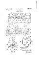
- Y Figure 1 is a top plan view of a pair of toyV fighters constructed in accordance with the principles of this invention.
- Figure 2 is a side elevation ol:l the base of one of the lighters together with the operating hand release means.
- Figure 3 is a rear view of the base of one of the lighters.
- Figure 4 is a detail view of one of the arms showing the mechanical' construction.
- Figure 5 is a rear view ofthe upper end portions.
- the reference numeral 10 indicates generally a casing or the like in which the toy 5 lighters ot this invention are mounted for operating purposes, the mounting kcomprising essentially a floor element l2 having a central longitudinal slot 14 therein, this slot being positioned midway of a pair of releases or the like 16.
- Each of the releases has mounted immediately above it a col-operating rail 18 as best shown in Figures l and 3.
- the lower rails 16 are fixed on the base 1&2, and the upper rails Alare removably mounted in the ends of the casing 10.
- each body having a pair of arms 22 pivotally mounted at its side to simulate a shoulder and jointed at the elbow It will be noted that the arms are attached at an angle so that the lists which are covered to simulate boxing gloves or the like 24 will be directed forwardly and in toward the center when moved into blow delivering positionv bythe operator.
- each arm comprises essentially a'cord, wire, or string 26, the upvper end of which is attached to a rearwardly extending rod28 which in turn is mounted on the inner end of a'shaft 30 rotatably positioned in a suitable openingin the body 32 of the dummy.
- At'the outer end oli' this shal't 30' is fastened a link member 34 which simulates vthe upper bone of the dummys arm.
- the forearm is represented by means of an extending element 36 pivotally mounted at 88 to the lower end of the upperarm piece, and mounted in an opening 40 in the lower end oliI the arm member 36 is a link .element 42, the upper end of which is pivotally positioned in an opening 44 formed in the ⁇ body just below and slightly behind the pivotal joint of the forearm mounting. This is best illustrated in Figures 4 and 5.
- a helical spring 46 is attached to the bottom member and to the middle portion4 of the upper arm element 34 so as to automatically retract the same into a normal position after operation.
- each arm piece together with the action of the link element 42 is such as to very closely simulate the actual human arm movement of a boXer striking a blow from the shoulder or upwardly.
- Each of the arms is so operated, an individual operating cord 26 being provided in every instance, these operating ycords passing downwardly behind the body member and behind the standard which supports the body and thronghlthe vslo.t.14 in the floor member 12, and each of these cords 26 is then connected to a correspond @4.
- the dummy is drawn foring one of another pair of cords 5.0 best shown in Figures 1 and'Q, these cords passing upwardly from ⁇ their.
- this means .comprising essentially a block 66 hingedly. mounted at 68 tothe block 56. ⁇
- This block 66 supports the standard'TO upon which in turn is mounted the body portiong32 of the dummy,.the same being provided with leg elements72 ⁇ whichare hingedly mounted .atthebottom edge-dof the body 32 and which will swing .forwardly fand rearwardly .accordingftothemotion ⁇ of the body, thereby ⁇ simulating the boxers leg action.
- aprojection or thelike 74 which ⁇ has normally in contact therewith a roller or the like 76 which is mounted in a. suitable bif-urcated support in the upper end of Va latching lever 7 8, thislatching leverbeing pivotally mounted adjacent its middle por tion ina bearing element 80 which is fastened to the forward portion of the'block 56.
- a spring 82 operatesato normally maintain the latching lever 78m proper locking relation withthe projecting lug 7.4 whereby'anyzmovement of the body, 32, standard and block 6.6 Yabout the'hinge 68 is prevented.
- a mechanical prize lighter a body having a head, arms and legs, and means for simulating and accomplishin arm movements to deliver and ward o blows, said means comprising a Isystem of Cords and pulleys, and means for simulating and accomplishing leg movements, and at the same time effecting' a forward or reverse movement of m the body, said means including an allied system of cords connected to the bodyland operated by manually controlled levers said firstnamed cords being connected to and shiftable with the body.
- a pair of toy lighters including in combination, two dummies, each dummy having a pair of jointed arms, and means for manually operating each of the arms, said means comprising a longitudinally rotatable rod mounted in the body of the dummy, a lateral extension on one end of the. rod, and a cord connected to the extension for rotating the rod, an upper arm element fixedly mounted on the other end of the rod, a forearm element pivotally mounted at the end of the upper arm element, and a link connecting a portion of the forearm element to the bod 3.
- a bo y having a head and arms, a supporting base for the body, said base comprising two blocks hinged together, and manually operated means for simulating and accomplishing arm movements to deliver and ward 0E blows, together with means for accomplishing body movements to avoid blows, and means for normally maintaining said body in upright p position, together with an automatically operated trip for releasing said positioning means.
- a body having a head and arms, and means for simulating and accomplishing arm movements to deliver and ward off blows, together Vwith means for automatically accomplishing leg movements, and means for normally maintaining said body in upright position, together with a trip for releasing said positioning means upon forward movement of the body and means associated with the body for 51" allowing of its overturning upon the delivery of a blow, when in said forward position.
Landscapes
- Toys (AREA)
Description
April 12, 1932.
M. T. LANE.
'roy FIGHTER Filed May 22, 1950 Patented Apr. Y12, 1932 OFFICE Y MICHAEL T. LANE, OF'CHICAGO, ILLINOIS TOY FIGHTER Appncation meavMay' 22, 1930.'.seria1 No. 454,707.
This invention relates to improvements in toy ghters, and has for one of its principal objects the provision of a pair ofanimated dolls or the like which simulate prize lighters, and which are adapted to be actuated manually b-y two operators, each operator controlling a doll, the object being to knock down the opponents doll.
One of the important objects of this invention is the provision in a pair of toy iighters of a body for each fighter simulating a human body having jointed arms, each of the. arms adapted to be thrust forwardly at the will of the operator and in accordance with a corresponding arm movement of the operator, and which armk movement vand construction is such as to very closely resemble an actual arm movement olf a prize lighter striking a blow.
Another and further important object of this invention is the provision in a pair of prize lighting dummies or the like of means for retaining the same upright through the operation of an automatically controlled latch which at a certain stage in the movement of the lighter is released, thereby allowing the lighter to be knocked down if struck while in such a release position, the release means being automatically re-latched upon the return of the dummy to its original zone of movement.
Other and further important objects of the invention will be apparent from the disclosures in the accompanying drawings and following specilication.
The invention, in a preferred form, is illustrated in the drawings and hereinafter more fully described.
In the drawings: g
Y Figure 1 is a top plan view of a pair of toyV fighters constructed in accordance with the principles of this invention.
Figure 2 is a side elevation ol:l the base of one of the lighters together with the operating hand release means.
Figure 3 is a rear view of the base of one of the lighters.
Figure 4 is a detail view of one of the arms showing the mechanical' construction.
Figure 5 is a rear view ofthe upper end portions.
of one of the fighters, showing the interior body construction. l
As shown in the drawings:
The reference numeral 10 indicates generally a casing or the like in which the toy 5 lighters ot this invention are mounted for operating purposes, the mounting kcomprising essentially a floor element l2 having a central longitudinal slot 14 therein, this slot being positioned midway of a pair of releases or the like 16. Each of the releases has mounted immediately above it a col-operating rail 18 as best shown in Figures l and 3. The lower rails 16 are fixed on the base 1&2, and the upper rails Alare removably mounted in the ends of the casing 10.
rlhe lighters themselves are represented at 2O in Figure l, each body having a pair of arms 22 pivotally mounted at its side to simulate a shoulder and jointed at the elbow It will be noted that the arms are attached at an angle so that the lists which are covered to simulate boxing gloves or the like 24 will be directed forwardly and in toward the center when moved into blow delivering positionv bythe operator.
The means for moving each arm comprises essentially a'cord, wire, or string 26, the upvper end of which is attached to a rearwardly extending rod28 which in turn is mounted on the inner end of a'shaft 30 rotatably positioned in a suitable openingin the body 32 of the dummy.
At'the outer end oli' this shal't 30'is fastened a link member 34 which simulates vthe upper bone of the dummys arm. The forearm is represented by means of an extending element 36 pivotally mounted at 88 to the lower end of the upperarm piece, and mounted in an opening 40 in the lower end oliI the arm member 36 is a link .element 42, the upper end of which is pivotally positioned in an opening 44 formed in the `body just below and slightly behind the pivotal joint of the forearm mounting. This is best illustrated in Figures 4 and 5. A helical spring 46 is attached to the bottom member and to the middle portion4 of the upper arm element 34 so as to automatically retract the same into a normal position after operation.
The pivotal mounting of each arm piece together with the action of the link element 42 is such as to very closely simulate the actual human arm movement of a boXer striking a blow from the shoulder or upwardly. Each of the arms is so operated, an individual operating cord 26 being provided in every instance, these operating ycords passing downwardly behind the body member and behind the standard which supports the body and thronghlthe vslo.t.14 in the floor member 12, and each of these cords 26 is then connected to a correspond @4. However, as the dummy is drawn foring one of another pair of cords 5.0 best shown in Figures 1 and'Q, these cords passing upwardly from` their. point of `juncture with the'cord 26, andeachjpassing .over a pulley wheel 52 mounted .in the bracket 54 fastened to the lower base ofthesupporting block 56lof the =dummy,.and thence pass- .ing forwardly .beneaththe iioor member 12,
to .another-.pulley 58 and finally upwardly throughy the slot 14 and overanother pulley `.60 whichis mounted in a bracket attached toa central Vcross-piece 62A and finally rearwardly again terminating in .a hook or the like 64 mounted inthe forward .portion of the block 56. Obviously, a pull yon either one of the joined cor.ds v26-`5O will Simultaneously operate the corresponding rightor left arm `of the dummy and move the .dummy forwardly into a position to strike a blow upon .the body or arm of the other dummy.
.Means are'providedso that-when the dummy is moved forwardly beyond a certain lpoint it is liable to be knocked .downif struck,
this means .comprising essentially a block 66 hingedly. mounted at 68 tothe block 56.` This block 66 supports the standard'TO upon which in turn is mounted the body portiong32 of the dummy,.the same being provided with leg elements72` whichare hingedly mounted .atthebottom edge-dof the body 32 and which will swing .forwardly fand rearwardly .accordingftothemotion `of the body, thereby `simulating the boxers leg action.
At the forward end of thelblockl 66.is mounted aprojection or thelike 74 which `has normally in contact therewith a roller or the like 76 which is mounted in a. suitable bif-urcated support in the upper end of Va latching lever 7 8, thislatching leverbeing pivotally mounted adjacent its middle por tion ina bearing element 80 which is fastened to the forward portion of the'block 56. A spring 82 operatesato normally maintain the latching lever 78m proper locking relation withthe projecting lug 7.4 whereby'anyzmovement of the body, 32, standard and block 6.6 Yabout the'hinge 68 is prevented.
Howeven the .lower portion of thelatchingbar 7 8 entends sidewise throughthe slot formed betweenthe members 16 .and.18, and
Vcessitated by the prior art.
'wardly through .the slot 86, leaving the roller 76 in locking relation with the projecting lug ward Vby means of the operation of the cord or vwire 50, the' lower projecting end of the latch .element 78 will strike the forward edge ofthe slot 86 andthe latch element `willbe accordingly tilted, thereby .releasing the roller Z-Gffrom contact with the lug .74,'an-d leaving the corresponding dummy inposition to be knocked over if struck at thatpar- .tion-lar time rand when in that position. 'Of course, as soon as the dummy .is .allowed to be retracted by release of the cord Orand action of the spring 90, the arm AT8 will again assume itsvertical position and a knockdown willbe impossible.
The casing in which the dummies are mountedis adapted to be positioned at.=a height of three or four4 feet lfrom .the .floor upon which the .operator stands, and the/,cords 26e-50 extend downwardly to the floor, and
are preferably connectedto operating levers or. the like positionedin a counter inifront @of which the operators stand, these operating Vlevers being connected to-.the cords in such a `manner that a forwardmotion .of the .lever ythe rollers 96 .are mounted on projecting pins .98, these rollers running between the rails so that the blocks and their corresponding dum- 'mies willy be positively maintainedin desired position at'all times.
lIt will be evidentthat: herein is .provideda set of toy fighters or thelikewhich'will-provide a source of interesting..amusement .for a -pair of players or operators, and which will so closely simulate human action that they will be doubly amusing while at the same time j providing a construction which is simple-'yet sturdy and `not vat all likely to get :out of order, evenunder conditions ofsevere-usage. I am aware that many changes may be made and numerous details of'construction i varied throughout a wide rangewithoutfdeparting from' the principles of thisinvention, and l,.therefore, do not purpose limitingthe patent granted( hereon otherwise than as nelli;
I claim as my inventionf 1. In a mechanical prize lighter, a body having a head, arms and legs, and means for simulating and accomplishin arm movements to deliver and ward o blows, said means comprising a Isystem of Cords and pulleys, and means for simulating and accomplishing leg movements, and at the same time effecting' a forward or reverse movement of m the body, said means including an allied system of cords connected to the bodyland operated by manually controlled levers said firstnamed cords being connected to and shiftable with the body.
2. A pair of toy lighters, including in combination, two dummies, each dummy having a pair of jointed arms, and means for manually operating each of the arms, said means comprising a longitudinally rotatable rod mounted in the body of the dummy, a lateral extension on one end of the. rod, and a cord connected to the extension for rotating the rod, an upper arm element fixedly mounted on the other end of the rod, a forearm element pivotally mounted at the end of the upper arm element, and a link connecting a portion of the forearm element to the bod 3. In a mechanical prize fighter, a bo y having a head and arms, a supporting base for the body, said base comprising two blocks hinged together, and manually operated means for simulating and accomplishing arm movements to deliver and ward 0E blows, together with means for accomplishing body movements to avoid blows, and means for normally maintaining said body in upright p position, together with an automatically operated trip for releasing said positioning means.
4:. In a mechanical prize fighter, a body having a head and arms, and means for simulating and accomplishing arm movements to deliver and ward off blows, together Vwith means for automatically accomplishing leg movements, and means for normally maintaining said body in upright position, together with a trip for releasing said positioning means upon forward movement of the body and means associated with the body for 51" allowing of its overturning upon the delivery of a blow, when in said forward position.
In testimony whereof I aif'lx my signature.
MICHAEL T. LANE.
Priority Applications (1)
| Application Number | Priority Date | Filing Date | Title |
|---|---|---|---|
| US454707A US1853733A (en) | 1930-05-22 | 1930-05-22 | Toy fighter |
Applications Claiming Priority (1)
| Application Number | Priority Date | Filing Date | Title |
|---|---|---|---|
| US454707A US1853733A (en) | 1930-05-22 | 1930-05-22 | Toy fighter |
Publications (1)
| Publication Number | Publication Date |
|---|---|
| US1853733A true US1853733A (en) | 1932-04-12 |
Family
ID=23805739
Family Applications (1)
| Application Number | Title | Priority Date | Filing Date |
|---|---|---|---|
| US454707A Expired - Lifetime US1853733A (en) | 1930-05-22 | 1930-05-22 | Toy fighter |
Country Status (1)
| Country | Link |
|---|---|
| US (1) | US1853733A (en) |
Cited By (5)
| Publication number | Priority date | Publication date | Assignee | Title |
|---|---|---|---|---|
| US2683954A (en) * | 1950-05-05 | 1954-07-20 | Lionel Corp | Animated toy |
| US4457097A (en) * | 1982-10-28 | 1984-07-03 | Hilco House, Inc. | Action toy and game |
| US4553946A (en) * | 1982-10-28 | 1985-11-19 | Hilco House, Inc. | Action toy and game |
| US5046987A (en) * | 1989-09-05 | 1991-09-10 | Simeon Djordjevic | Toy boxer arms |
| US11413552B1 (en) * | 2021-11-01 | 2022-08-16 | Dongguan Chuangmei Industrial Design Co., Ltd. | Bamboo tube fighting toy |
-
1930
- 1930-05-22 US US454707A patent/US1853733A/en not_active Expired - Lifetime
Cited By (5)
| Publication number | Priority date | Publication date | Assignee | Title |
|---|---|---|---|---|
| US2683954A (en) * | 1950-05-05 | 1954-07-20 | Lionel Corp | Animated toy |
| US4457097A (en) * | 1982-10-28 | 1984-07-03 | Hilco House, Inc. | Action toy and game |
| US4553946A (en) * | 1982-10-28 | 1985-11-19 | Hilco House, Inc. | Action toy and game |
| US5046987A (en) * | 1989-09-05 | 1991-09-10 | Simeon Djordjevic | Toy boxer arms |
| US11413552B1 (en) * | 2021-11-01 | 2022-08-16 | Dongguan Chuangmei Industrial Design Co., Ltd. | Bamboo tube fighting toy |
Similar Documents
| Publication | Publication Date | Title |
|---|---|---|
| US2716840A (en) | Mechanical boxer toy | |
| US2123195A (en) | Game apparatus | |
| US1853733A (en) | Toy fighter | |
| US2419990A (en) | Hare and tortoise toy | |
| US1501912A (en) | Dancing doll | |
| US2254091A (en) | Mechanical orchestra | |
| US2018833A (en) | Game and game apparatus | |
| US2819082A (en) | Simulated hockey game | |
| US1745434A (en) | Toy | |
| US1636042A (en) | Figure toy | |
| US1591521A (en) | Jumping toy | |
| US1715798A (en) | Projecting-figure toy | |
| US1644047A (en) | Mechanical toy | |
| US2168425A (en) | Walking animal toy | |
| US2713748A (en) | Acrobatic figure toy | |
| US1539251A (en) | Device for playing table football | |
| US1834165A (en) | Manikin toy | |
| US2393289A (en) | Toy | |
| US1812253A (en) | Game | |
| US1334578A (en) | Dancing toy | |
| US1605307A (en) | Walking toy | |
| US1384963A (en) | Amusement device | |
| US1241937A (en) | Toy. | |
| US1714031A (en) | Toy figure | |
| US1603038A (en) | Toy |