US1853724A - Evaporating process and apparatus - Google Patents
Evaporating process and apparatus Download PDFInfo
- Publication number
- US1853724A US1853724A US294999A US29499928A US1853724A US 1853724 A US1853724 A US 1853724A US 294999 A US294999 A US 294999A US 29499928 A US29499928 A US 29499928A US 1853724 A US1853724 A US 1853724A
- Authority
- US
- United States
- Prior art keywords
- liquid
- conduit
- chamber
- evaporator
- emulsion
- Prior art date
- Legal status (The legal status is an assumption and is not a legal conclusion. Google has not performed a legal analysis and makes no representation as to the accuracy of the status listed.)
- Expired - Lifetime
Links
- 238000000034 method Methods 0.000 title description 10
- 238000001704 evaporation Methods 0.000 title description 9
- 239000007788 liquid Substances 0.000 description 61
- 239000000839 emulsion Substances 0.000 description 14
- 239000010408 film Substances 0.000 description 11
- 230000001174 ascending effect Effects 0.000 description 9
- 239000003507 refrigerant Substances 0.000 description 8
- 238000007599 discharging Methods 0.000 description 6
- 230000000694 effects Effects 0.000 description 4
- 230000008020 evaporation Effects 0.000 description 4
- 239000012530 fluid Substances 0.000 description 3
- 235000013305 food Nutrition 0.000 description 3
- 238000009834 vaporization Methods 0.000 description 3
- 230000008016 vaporization Effects 0.000 description 3
- 238000001816 cooling Methods 0.000 description 2
- 238000005057 refrigeration Methods 0.000 description 2
- 239000010409 thin film Substances 0.000 description 2
- 241000896693 Disa Species 0.000 description 1
- 230000006978 adaptation Effects 0.000 description 1
- QWGDMFLQWFTERH-UHFFFAOYSA-N amoxapine Chemical compound C12=CC(Cl)=CC=C2OC2=CC=CC=C2N=C1N1CCNCC1 QWGDMFLQWFTERH-UHFFFAOYSA-N 0.000 description 1
- 239000012267 brine Substances 0.000 description 1
- 239000011248 coating agent Substances 0.000 description 1
- 238000000576 coating method Methods 0.000 description 1
- 238000010276 construction Methods 0.000 description 1
- 230000008014 freezing Effects 0.000 description 1
- 238000007710 freezing Methods 0.000 description 1
- 239000013505 freshwater Substances 0.000 description 1
- 230000005484 gravity Effects 0.000 description 1
- 238000010438 heat treatment Methods 0.000 description 1
- 230000001788 irregular Effects 0.000 description 1
- 239000012263 liquid product Substances 0.000 description 1
- 235000013372 meat Nutrition 0.000 description 1
- 238000012986 modification Methods 0.000 description 1
- 230000004048 modification Effects 0.000 description 1
- 239000000047 product Substances 0.000 description 1
- 238000005086 pumping Methods 0.000 description 1
- HPALAKNZSZLMCH-UHFFFAOYSA-M sodium;chloride;hydrate Chemical compound O.[Na+].[Cl-] HPALAKNZSZLMCH-UHFFFAOYSA-M 0.000 description 1
- 230000001131 transforming effect Effects 0.000 description 1
Images
Classifications
-
- F—MECHANICAL ENGINEERING; LIGHTING; HEATING; WEAPONS; BLASTING
- F25—REFRIGERATION OR COOLING; COMBINED HEATING AND REFRIGERATION SYSTEMS; HEAT PUMP SYSTEMS; MANUFACTURE OR STORAGE OF ICE; LIQUEFACTION SOLIDIFICATION OF GASES
- F25B—REFRIGERATION MACHINES, PLANTS OR SYSTEMS; COMBINED HEATING AND REFRIGERATION SYSTEMS; HEAT PUMP SYSTEMS
- F25B41/00—Fluid-circulation arrangements
-
- F—MECHANICAL ENGINEERING; LIGHTING; HEATING; WEAPONS; BLASTING
- F25—REFRIGERATION OR COOLING; COMBINED HEATING AND REFRIGERATION SYSTEMS; HEAT PUMP SYSTEMS; MANUFACTURE OR STORAGE OF ICE; LIQUEFACTION SOLIDIFICATION OF GASES
- F25B—REFRIGERATION MACHINES, PLANTS OR SYSTEMS; COMBINED HEATING AND REFRIGERATION SYSTEMS; HEAT PUMP SYSTEMS
- F25B2341/00—Details of ejectors not being used as compression device; Details of flow restrictors or expansion valves
- F25B2341/001—Ejectors not being used as compression device
- F25B2341/0012—Ejectors with the cooled primary flow at high pressure
-
- F—MECHANICAL ENGINEERING; LIGHTING; HEATING; WEAPONS; BLASTING
- F25—REFRIGERATION OR COOLING; COMBINED HEATING AND REFRIGERATION SYSTEMS; HEAT PUMP SYSTEMS; MANUFACTURE OR STORAGE OF ICE; LIQUEFACTION SOLIDIFICATION OF GASES
- F25D—REFRIGERATORS; COLD ROOMS; ICE-BOXES; COOLING OR FREEZING APPARATUS NOT OTHERWISE PROVIDED FOR
- F25D11/00—Self-contained movable devices, e.g. domestic refrigerators
- F25D11/02—Self-contained movable devices, e.g. domestic refrigerators with cooling compartments at different temperatures
- F25D11/022—Self-contained movable devices, e.g. domestic refrigerators with cooling compartments at different temperatures with two or more evaporators
Definitions
- This invention relates to the evaporation of liquids and includes both a process and apparatus for carrying out the process. ile
- the invention has features of general applica- 5 tion, it is particularly adapted and intended for refrigerating purposes. More articularly' it has to do with refrigerating systems operating on the vapor-gas principle disclosed in my U. S. Patent No. 1,619,196,
- One object of the invention is still further to increase the contact area between the liquid and gaseous fluids in the evaporator.
- Another object is to improve the distribution of the evaporating liquid. Another object is to move or circulate the liquid in a given direction within the evaporator. A still fur- 80 ther object is to utilize the activity of the evaporating liquid to eifect the movement 0 the residual liquid and to spread the same as a.thin film or coating upon the evaporating surfaces so-.as to augment the quantity 0 vapor released and to release the same in a continuous stream.
- a closed cycle system in which are pro vided suitable means to move and condense 40 evaporator through a feeding device of any suitable or desired type. It is merely necessary that the gas and the liquid from the condenser be available, either mixed or separate, for feeding into the evaporator.
- the evaporator itsel is of novel construction and combines means for forming and holding the refrigerant liquid in a state of froth or emulreading a liquid film in heat sion and for sp absorbing relation with the refrigerator.
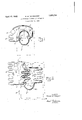
- F g. 1 is a somewhat diagrammatic illustra(t1on of a simple form of the invention.
- Fig. 2 is a similar view showing a more. practical and preferred arrangement.
- A is the pump or compressor,-B the condenser discharging through pipe I) mto the evaporator indicated generally at C the latter being maintained under reduce pressure by a connection 0 to compressor A.
- These elements are connected together to form a closed cycle sytem and the compressor and the condenser may be of any suitable or desired type.
- v conduit 5 may extend partly into and through chamber 3 and have a flared outer end enclosing the feeding nozzle 4, the better to direct the emulsified liquid through conduit v 5.
- Conduit 5 may be arched or curved .to provide an ascending portion 5a and a descending portion 5?). The velocity of movement of the frothy emulsion together with the action of pump A in reducing the pressure causesmuch of the liquid to vaporize.
- the residual li uid gathers as a film or dew upon the walls the conduit 5 and drains down the descending part 56 into discharge chamber 6.
- a bafiie 7 in the chamber prevents the liquid from pasing directly into discharge outlet chamber 6 is connected wit inlet chamher 4 by a second conduit 8 which preferably extends beneath both chambers to form a liquid seal or trap. Through this conduit 8 the unevaporated liquid passes back to the inlet chamber 3.
- evaporator In the form shown in Fig. 2 the evaporator is somewhat more elaborate but the operation is substantially identical.
- the gas and vapor withdrawn through pipe 0 by pump A are discharged at higher temperature and pressure into condenser B and thereafter are fed through pipe 6 and discharged through a suitable feeding device 4' into inlet chamber 3 of evaporator C.
- the resulting froth mass or emulsion overflows from cham er 3 and passes through the ascending conduit 9 (where heat is absorbed to vaporize the entrained liquid). It discharges into outlet chamberb whichhas a baflle 7 for preventing the liquid from passing directly into pipe C.
- Conduit 10 extends from outlet chamber 6' as a descending member for returning the residual liquid to inlet chamber 3' and has at its lower portion a loop 10a to form a trap or liquid seal. Obviously the greater part of the vaporization takes place in the ascending conduit or coil 9 and this portion of the evaporator may be utilized for the freezing of liquids either by placing the conduit 9 in an insulated chamber (of a refrigerator indicated diagrammatically at X) or within a brine tank and disposing trays 11 containing the liquids to be frozen in thermal proximity thereto.
- the descending conduit or coil 10 which receives the residual liquid from the emulsion passing through conduit 9 in the form of a thin film upon its walls, conducts the same by gravity into trap 10a and thence into inlet chamber 3, the liquid film meantime receiving heat from the food compartment of refrigerator X and thereby becoming at least partly vaporized since it continues to be under the reduced pressure created by pump A.
- the liquid in conduits 5b and 10 is in the form of fied liquid and the rest of it into a film of liquid refrigerant formed and distributed by the activity of the emulsion and spread thinly over the extensive surfaces warmed by the refrigerator.
- This arrangement requires less work to be done on the liquid, and the liquid area in contact with the heated surface can be increased in better proportion to the contact area between the liquid and vapor. It is also evident that less weight of air or gas is required in a given time to produce and maintain the given contact areas. It is to be noted that this invention diflers from that set forth in my copending application Serial N 0.
- the process of refrigeration which comprises discharging liquid and sure into a chamber so as to form a frothy mass or emulsion, supplying heat at lower temperatures to said chamber, conducting the overflow from said chamber into an elongate vessel and supplying heat thereto to vaporize the liquid component of the emulsion, reducing the pressure in said vessel to effect release of a continuous stream of vapor, and
- Refrigerating apparatus providing -a chamber containing evaporable liquid means for discharging into said chamber additional emulsion, a conduit for receiving the overflow from said chamber, means subjecting said conduit to suction pressure to effect vaporization of ,the liquid in said conduit, and a conduit also under suction pressure for rece ving the liquid as a thin layer or film distributed thereon and for returning the unvaporized portion of such liquid to said chamber said last-named conduit providing a liquid seal for said chamber.
- Refrigerating apparatus of the closed cycle type comprising a compressor, a condenser, and an evaporator, said evaporator providing an inlet chamber connected to said condenser and ari outlet chamber connected to said compressor, and conduits providing separate fluid paths between said chambers, one of said conduits providing an extended surface area and a liquid seal.
- Refrigerating apparatus of the closed cycle type comprising denser, an evaporator said evaporator'providing an inlet cham er connected to said condenser and an outlet chamber connected to said compressor, separate conduits interconnecting said chambers, one of said conduits extending beneath the lowermost of said chambers to provide a liquid seal, the connection from said condenser terminating as a nozzle within said inlet chamber for discharging a gas under an ascending column 0 emulsion or ii uid froth in one of said conduits, the seal con uit servin as a retur for an unvaporized liquid w 'ch so are es out om the emulsion 3r froth and orms a film upon the latter conuit.
- Refrigerating apparatus comprising-an evaporator havincgl ascending and escen 'ng parts, means for 'scharging into said evaporator beneath said ascending part an evaporable liquid and a gas to form an emulsion in said ascending part and a film of liquid over the walls of said descending part, means subjecting said evaporator to suction pressure, said descending part being in the form of a coil of pipe whose internal walls form an a compressor, a .conv pressure to produce dethe extended area and which terminates in a pressed portion or trap for returning to vicinity of said discharge the liqui evaporated in said ascending and descending parts.
- Refrigerating apparatus of the closedcycle type operating on the vapor-gas principle having an evaporator providing an inlet chamber containing refrigerant liquid, means discharging a vapor-gas liquid stream into said liquid, an ascending conduit for theemulsion or froth overflowing from said receptacles for liquid to be said conduit, an outlet chamber into which said conduit discharges, and a return conduit from said outlet chamber to said inlet chamber providing a liquid seal for the latter but otherwise unobstructed, the walls of said return conduit being 'wet with a film of residual liquid from said emulsion or froth, said return conduit being arranged for cooling the food compartment of a refrigerator cabinet. Signed by meat Detroit, in the county of Wayne and State of Michigan this 19th day of July, 1928. RANSOM W. DAVENPORT.
Landscapes
- Engineering & Computer Science (AREA)
- Physics & Mathematics (AREA)
- Mechanical Engineering (AREA)
- Thermal Sciences (AREA)
- General Engineering & Computer Science (AREA)
- Vaporization, Distillation, Condensation, Sublimation, And Cold Traps (AREA)
Description
R. W. DAVENPORT EVAPORATING PROCESS AND APPARATUS A ril 12,1932.
Filed July 24, 1928 INVENTOR. Ransom W flm enparf J W A TTORNE Y.
Patented Apr. 1 2, 1932 2 UNITED STATES PATENT. OFFICE;
BANSOM DAVENPORT, OI DETROIT, MICHIGAN, ASSIGNOB TO CHICAGO PNEUMATIC TOOL COMPANY, OF NEW YORK, N. Y., A CORPORATION OF NEW JERSEY EVAPOBA'IING PROCESS AND APPARATUS 1 Application filed July 24, 1928. Serial No. 294,999. I
This invention relates to the evaporation of liquids and includes both a process and aparatus for carrying out the process. ile
the invention has features of general applica- 5 tion, it is particularly adapted and intended for refrigerating purposes. More articularly' it has to do with refrigerating systems operating on the vapor-gas principle disclosed in my U. S. Patent No. 1,619,196,
1 issued March 1, 1927, disclosing the use of air or other insoluble gas in evaporators to prevent super-heating duringvaporization of the liquid refrigerant and to secure lower temperatures with a given total pressure than is possible to secure by the conventional straight pumping methods. As previously disclosed the gas has been utilized to agitate and distend the liquid so as to increase the contactarea of the gaseous and liquid fluids within the evaporator thereby p to increase the "quantity of vapor released from the liquid.
One object of the invention is still further to increase the contact area between the liquid and gaseous fluids in the evaporator.
Another object is to improve the distribution of the evaporating liquid. Another object is to move or circulate the liquid in a given direction within the evaporator. A still fur- 80 ther object is to utilize the activity of the evaporating liquid to eifect the movement 0 the residual liquid and to spread the same as a.thin film or coating upon the evaporating surfaces so-.as to augment the quantity 0 vapor released and to release the same in a continuous stream.
In carrying out the invention, I prefer to use a closed cycle system in which are pro vided suitable means to move and condense 40 evaporator through a feeding device of any suitable or desired type. It is merely necessary that the gas and the liquid from the condenser be available, either mixed or separate, for feeding into the evaporator. The evaporator itsel is of novel construction and combines means for forming and holding the refrigerant liquid in a state of froth or emulreading a liquid film in heat sion and for sp absorbing relation with the refrigerator.
- will now be given.
f charge is through the vapor and to feed the condensate to the P In order to illustrate the invention, concreteembodiments thereof are shown in the accompanying drawings in which:
F g. 1 is a somewhat diagrammatic illustra(t1on of a simple form of the invention; an
Fig. 2 is a similar view showing a more. practical and preferred arrangement.
In Fig. l, A is the pump or compressor,-B the condenser discharging through pipe I) mto the evaporator indicated generally at C the latter being maintained under reduce pressure by a connection 0 to compressor A. These elements are connected together to form a closed cycle sytem and the compressor and the condenser may be of any suitable or desired type.
Inasmuch as the novelty of the present invention resides in the evaporator and in the roces's steps relating to vaporiz tion of the refrigerant, detailed description of the same The products of the condenser B (condensate, residual vapor and gas) are discharged into an inlet chamber 3 of restricted size which contains a quantity of the liquid refrigerant. While the gaseous and the liquid products of the condenser may be directed into the inlet chamber 3 separately, if desired, in the present instance they enter together through a single feed f device A which may be a Venturi nozzle discharging slightly below the surface of the body of liquid refrigerant. Since the disa restricted orifice considerable velocity is acquired with the result that the liquid in chamber 3 is transformed into a frothy mass or emulsion which is arranged to overflow into a conduit 5 extending to a second chamber 6 which is connected by a ipe C directly to pump A. If desired, the
v conduit 5 may extend partly into and through chamber 3 and have a flared outer end enclosing the feeding nozzle 4, the better to direct the emulsified liquid through conduit v 5. Conduit 5 may be arched or curved .to provide an ascending portion 5a and a descending portion 5?). The velocity of movement of the frothy emulsion together with the action of pump A in reducing the pressure causesmuch of the liquid to vaporize.
As the vapor and the gas release themselves from the frothy mass, the residual li uid gathers as a film or dew upon the walls the conduit 5 and drains down the descending part 56 into discharge chamber 6. A bafiie 7 in the chamber prevents the liquid from pasing directly into discharge outlet chamber 6 is connected wit inlet chamher 4 by a second conduit 8 which preferably extends beneath both chambers to form a liquid seal or trap. Through this conduit 8 the unevaporated liquid passes back to the inlet chamber 3.
In the form shown in Fig. 2 the evaporator is somewhat more elaborate but the operation is substantially identical. The gas and vapor withdrawn through pipe 0 by pump A are discharged at higher temperature and pressure into condenser B and thereafter are fed through pipe 6 and discharged through a suitable feeding device 4' into inlet chamber 3 of evaporator C. The resulting froth mass or emulsion overflows from cham er 3 and passes through the ascending conduit 9 (where heat is absorbed to vaporize the entrained liquid). It discharges into outlet chamberb whichhas a baflle 7 for preventing the liquid from passing directly into pipe C. Conduit 10 extends from outlet chamber 6' as a descending member for returning the residual liquid to inlet chamber 3' and has at its lower portion a loop 10a to form a trap or liquid seal. Obviously the greater part of the vaporization takes place in the ascending conduit or coil 9 and this portion of the evaporator may be utilized for the freezing of liquids either by placing the conduit 9 in an insulated chamber (of a refrigerator indicated diagrammatically at X) or within a brine tank and disposing trays 11 containing the liquids to be frozen in thermal proximity thereto. The descending conduit or coil 10, which receives the residual liquid from the emulsion passing through conduit 9 in the form of a thin film upon its walls, conducts the same by gravity into trap 10a and thence into inlet chamber 3, the liquid film meantime receiving heat from the food compartment of refrigerator X and thereby becoming at least partly vaporized since it continues to be under the reduced pressure created by pump A.
Both the process and the apparatus are available for commercial as well as domestic refrigeration since provision is made both for the making of ice and the cooling of food. Obviously little or no liquid refrigerant will be available for the descending coil 10' so long as the amount of evaporation in the ascendin coil 9 is large, which results from much system is first put into operation or when freshwater is put into the trays 11 to be frozen. As soon as the liquid is frozen and much less heat is taken into coil 9, the evapopipe 0. Theeat to be transformed, as when the ration in this lportion of the eva rator becomes relative y negligible and t e descending coil 10 may become wet throughout with the bulk of the evaporation taking place in this portion of the evaporator. Smce the liquid in conduits 5b and 10 is in the form of fied liquid and the rest of it into a film of liquid refrigerant formed and distributed by the activity of the emulsion and spread thinly over the extensive surfaces warmed by the refrigerator. This arrangement requires less work to be done on the liquid, and the liquid area in contact with the heated surface can be increased in better proportion to the contact area between the liquid and vapor. It is also evident that less weight of air or gas is required in a given time to produce and maintain the given contact areas. It is to be noted that this invention diflers from that set forth in my copending application Serial N 0. 123,912, filed J uly'21, 1926, for processes of and apparatus for transforming heat in that the non-agitated or non-emulsified portion of the liquid is in the present invention spread out as a film and in that the stream of vapor formed by the evaporation of the film flows continuously to the pump. and shows that the boundary between the vapor and the liquid streams is always free and extensive. This contrasts with my aforementioned application Serial No. 123,912 in which the nonemulsified liquid mass is required to boil and the released vapor must force its way out against liquid head and resistance, not in a continuous stream, but as irregular and occasional bubbles.
While the invention has been herein disclosed both as to its process and apparatus aspects in what are now considered to be preferred forms, it is to be understood that the invention is not limited to the specific details thereof but covers all changes, modifications,and adaptations within the the appended claims.
I claim as my invention:
1. The process of refrigeration which comprises discharging liquid and sure into a chamber so as to form a frothy mass or emulsion, supplying heat at lower temperatures to said chamber, conducting the overflow from said chamber into an elongate vessel and supplying heat thereto to vaporize the liquid component of the emulsion, reducing the pressure in said vessel to effect release of a continuous stream of vapor, and
scope of.
gas under presliquid and a gas so as to form an cause vaporization of the liquid component.
of ti emulsion, disposing a portion of the liquid-from the emulsion as a film to present a maximum of extended surface subjected to said low pressure, and returning the untyaporized portion of the liquid to said cham- 3. Refrigerating apparatus providing -a chamber containing evaporable liquid means for discharging into said chamber additional emulsion, a conduit for receiving the overflow from said chamber, means subjecting said conduit to suction pressure to effect vaporization of ,the liquid in said conduit, and a conduit also under suction pressure for rece ving the liquid as a thin layer or film distributed thereon and for returning the unvaporized portion of such liquid to said chamber said last-named conduit providing a liquid seal for said chamber.
4. Refrigerating apparatus of the closed cycle type comprising a compressor, a condenser, and an evaporator, said evaporator providing an inlet chamber connected to said condenser and ari outlet chamber connected to said compressor, and conduits providing separate fluid paths between said chambers, one of said conduits providing an extended surface area and a liquid seal.
5. Refrigerating apparatus of the closed cycle type comprising denser, an evaporator said evaporator'providing an inlet cham er connected to said condenser and an outlet chamber connected to said compressor, separate conduits interconnecting said chambers, one of said conduits extending beneath the lowermost of said chambers to provide a liquid seal, the connection from said condenser terminating as a nozzle within said inlet chamber for discharging a gas under an ascending column 0 emulsion or ii uid froth in one of said conduits, the seal con uit servin as a retur for an unvaporized liquid w 'ch so are es out om the emulsion 3r froth and orms a film upon the latter conuit.
6. Refrigerating apparatus comprising-an evaporator havincgl ascending and escen 'ng parts, means for 'scharging into said evaporator beneath said ascending part an evaporable liquid and a gas to form an emulsion in said ascending part and a film of liquid over the walls of said descending part, means subjecting said evaporator to suction pressure, said descending part being in the form of a coil of pipe whose internal walls form an a compressor, a .conv pressure to produce dethe extended area and which terminates in a pressed portion or trap for returning to vicinity of said discharge the liqui evaporated in said ascending and descending parts.
7. Refrigerating apparatus of the closedcycle type operating on the vapor-gas principle having an evaporator providing an inlet chamber containing refrigerant liquid, means discharging a vapor-gas liquid stream into said liquid, an ascending conduit for theemulsion or froth overflowing from said receptacles for liquid to be said conduit, an outlet chamber into which said conduit discharges, and a return conduit from said outlet chamber to said inlet chamber providing a liquid seal for the latter but otherwise unobstructed, the walls of said return conduit being 'wet with a film of residual liquid from said emulsion or froth, said return conduit being arranged for cooling the food compartment of a refrigerator cabinet. Signed by meat Detroit, in the county of Wayne and State of Michigan this 19th day of July, 1928. RANSOM W. DAVENPORT.
not
chamber, frozen adjacent
Priority Applications (1)
| Application Number | Priority Date | Filing Date | Title |
|---|---|---|---|
| US294999A US1853724A (en) | 1928-07-24 | 1928-07-24 | Evaporating process and apparatus |
Applications Claiming Priority (1)
| Application Number | Priority Date | Filing Date | Title |
|---|---|---|---|
| US294999A US1853724A (en) | 1928-07-24 | 1928-07-24 | Evaporating process and apparatus |
Publications (1)
| Publication Number | Publication Date |
|---|---|
| US1853724A true US1853724A (en) | 1932-04-12 |
Family
ID=23135803
Family Applications (1)
| Application Number | Title | Priority Date | Filing Date |
|---|---|---|---|
| US294999A Expired - Lifetime US1853724A (en) | 1928-07-24 | 1928-07-24 | Evaporating process and apparatus |
Country Status (1)
| Country | Link |
|---|---|
| US (1) | US1853724A (en) |
Cited By (7)
| Publication number | Priority date | Publication date | Assignee | Title |
|---|---|---|---|---|
| US2563575A (en) * | 1951-08-07 | Absorption refrigeration | ||
| US2581466A (en) * | 1948-02-03 | 1952-01-08 | Carrier Corp | Means for maintaining liquid level in heat-exchange apparatus |
| US2598737A (en) * | 1947-02-28 | 1952-06-03 | Electrolux Ab | Refrigerator having multiple temperature cooling elements |
| US2633007A (en) * | 1948-11-19 | 1953-03-31 | Stator Company | Injector type refrigerating system |
| US2776548A (en) * | 1954-01-26 | 1957-01-08 | Martiri Roberto | Vertical generators for absorption refrigeration units |
| US4972678A (en) * | 1989-11-24 | 1990-11-27 | Finlayson Donald F | Refrigeration and heat exchange system and process |
| EP0624763A1 (en) * | 1993-05-10 | 1994-11-17 | General Electric Company | Free-draining evaporator for refrigeration system |
-
1928
- 1928-07-24 US US294999A patent/US1853724A/en not_active Expired - Lifetime
Cited By (7)
| Publication number | Priority date | Publication date | Assignee | Title |
|---|---|---|---|---|
| US2563575A (en) * | 1951-08-07 | Absorption refrigeration | ||
| US2598737A (en) * | 1947-02-28 | 1952-06-03 | Electrolux Ab | Refrigerator having multiple temperature cooling elements |
| US2581466A (en) * | 1948-02-03 | 1952-01-08 | Carrier Corp | Means for maintaining liquid level in heat-exchange apparatus |
| US2633007A (en) * | 1948-11-19 | 1953-03-31 | Stator Company | Injector type refrigerating system |
| US2776548A (en) * | 1954-01-26 | 1957-01-08 | Martiri Roberto | Vertical generators for absorption refrigeration units |
| US4972678A (en) * | 1989-11-24 | 1990-11-27 | Finlayson Donald F | Refrigeration and heat exchange system and process |
| EP0624763A1 (en) * | 1993-05-10 | 1994-11-17 | General Electric Company | Free-draining evaporator for refrigeration system |
Similar Documents
| Publication | Publication Date | Title |
|---|---|---|
| US2592712A (en) | Portable refrigerator | |
| US3177680A (en) | Refrigeration system with oil return means | |
| US1853724A (en) | Evaporating process and apparatus | |
| US3977204A (en) | Alcohol circulation system | |
| US2248178A (en) | Refrigeration | |
| US2724246A (en) | Method and means for improving the utilization of volatile refrigerants in heat exchangers | |
| US2350115A (en) | Refrigerating system | |
| US2855765A (en) | Absorption refrigeration apparatus | |
| US2099085A (en) | Superheat control for refrigeration systems | |
| US2016056A (en) | Liquid circulating system | |
| US1735995A (en) | Refrigerating system | |
| US1944472A (en) | Art of refrigeration | |
| US1849685A (en) | Refrigeration | |
| US2426069A (en) | Refrigeration | |
| US3301005A (en) | Purge arrangement for absorption refrigeration systems | |
| US2345714A (en) | Refrigerating apparatus | |
| JPH0339867A (en) | Jet ejector type refrigeration method and apparatus | |
| US2315356A (en) | Refrigeration | |
| US1769112A (en) | Process of and apparatus for transforming heat | |
| US1874621A (en) | Refrigeration | |
| US3314247A (en) | Integral preheater and sub-cooling for generator of absorption refrigeration systemsor equivalent component of another system | |
| US1433040A (en) | Method of continuously evaporating liquids and in evaporating apparatus | |
| US1996094A (en) | Absorption refrigerating apparatus and method | |
| US2136395A (en) | Apparatus for refrigeration | |
| US2633007A (en) | Injector type refrigerating system |