US1853722A - Work support for staple fastening machines - Google Patents
Work support for staple fastening machines Download PDFInfo
- Publication number
- US1853722A US1853722A US382855A US38285529A US1853722A US 1853722 A US1853722 A US 1853722A US 382855 A US382855 A US 382855A US 38285529 A US38285529 A US 38285529A US 1853722 A US1853722 A US 1853722A
- Authority
- US
- United States
- Prior art keywords
- counter
- positioning member
- machine
- clenching
- anvil
- Prior art date
- Legal status (The legal status is an assumption and is not a legal conclusion. Google has not performed a legal analysis and makes no representation as to the accuracy of the status listed.)
- Expired - Lifetime
Links
- 238000004519 manufacturing process Methods 0.000 description 1
- 239000000463 material Substances 0.000 description 1
- 239000011435 rock Substances 0.000 description 1
Images

Classifications
-
- A—HUMAN NECESSITIES
- A43—FOOTWEAR
- A43D—MACHINES, TOOLS, EQUIPMENT OR METHODS FOR MANUFACTURING OR REPAIRING FOOTWEAR
- A43D44/00—Machines for attaching welts or rands
Definitions
- This invention relates to fastening inserting machines and is illustrated herein as embodied in a counter stapling machine.
- a feature of the invention as embodied in the illustrated machine, comprises an improved work support having a countershaped work positioning member arranged to engage the rear end of a counter thereby positioning the counter longitudinally and a pair of resilient members arranged to engage the Wings of the counter adjacent to their forward ends for positioning the counter transversely.
- a further object of the invention is to provide means for positioning a counter for the reception of a second fastening means.
- the Work positioning member is provided with a yieldably mountedplunger projecting from' the rear portion of the counter positioning member.
- the counter will be positioned longitudinally i-none position or another according as the plunger occupies one or the other of its extreme positions.
- Another object of the invention is to provide a work positioning member which may be readily detached from the machine to permitthe work positioning member to be replaced by another work positioning member adapted to position a different sizedcounter. Accordingly, a feature of the invention resides in the provision of means for detachably securing the positioning member to the horn of the machine to permit the positioning member to be replaced by a positioning memb-er of a different size.
- Another object of the invention is to provide means whereby the work positioning member may be readily. removed from the machine without disturbing the location and arrangement of the clenching anvil relative ⁇ ly to the staple inserting instrumentalities of the machine.
- a feature of the invention resides in a work positioning member provided on its upper surface with apertures arranged to receive the clenching anvil and means for detachably securing the work positioning member to the horn of the machine to allow the vvork positioning member to be removed without type of anvil having two clenching cavities placed in alinement with each other, but since one or both of the points would then be slightly offset with respectto its clenching cavity it is desired to locate the clenching cavities in a manner to improve the clenching of the staples.
- an'object of the invention is 'to locate the clenching cavities in such a way that they can herelied upon better to clench bothpoints orlegs of each staple inserted by the machine.
- the anvil is provided with clench ing cavities which are offset from each relatively to the fastening inserting means of the machine.
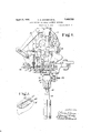
- Fig. 1 is a front elevation of the head and Work support of a fastening inserting ma chine embodying the present invention
- Fig. 2 is a side elevation of the work support of the machine of Fig. 1;
- Fig. 3 is a plan View of the work support of Fig. 2;
- Fig. 4 is an exploded view of the work positioning member
- Fig. 5 is a aerspective view of a counter the spread of t e forepart of which is determined by staples inserted by the illustrated machine.
- the illustrated machine is of the character disclosed in Letters Patent of the United States No. 1,016,930, granted February 13, 1912, on an application filed in the name of William H. Borden.
- This machine is well-known to the trade and as many of the details of the machine are of no conse quence so far as the present invention is concerned, it has not been found necessary to describe the machine in full, only such parts being shown and described herein as are necessary or helpful to an understanding of the present invention.
- For a full disclosure of the remaining details of the machine reference may be had to said Letters Patent No. 1,016,930.
- the illustrated machine is provided with a head in which is mounted a main cam shaft carrying a lifting cam 12 in operative relation to a lifting block 14 carried by a driver bar 16 mounted for vertical movement in ways carried by the head of the machine and moved downwardly when the lifting cam 12 moves from under the lifting block 14 by a suitable spring in a well-known fashion.
- a driver 18 Secured to the lower end of the driver bar 16 is a driver 18 reciprocating through a driver passage 20.
- the driver 18 is in the -form of a fiat plate (Fig. 1) and the driver passage 20, which is formed in a driver guide and throat member 22, is of similar cross section.
- An inside former 24 is mounted for forward 3 and rearward movement into and out of the driver passage and cooperates with a pair of outside formers 26 reciprocated in timed rela tion to the inside former 24 and the driver 18 by suitable mechanism including a rock arm 28 carried by a shaft 30 rocked by suitable connections from the shaft 10.
- a pair of feed rolls 32 are operative to feed a wire 34 past a pair of cutters 36 and 38 into position above the inside former 24 and beneath the outside formers 26.
- the outside formers 26 are moved downwardly, wiping the end portions of the Wire 40 about the inside former 24 and thus forming a staple having a long bar and short legs, as illustrated at and 47 in Fig. 5.
- the inside former 24 is withdrawn and the driver 18 moved downwardly to drive the staple into the forward portions of the flange 43 of a counter 45 presented thereto.
- a bracket 46 Attached to a horn post 44, such as is commonly used in such machines, and mounted for vertical movement therewith, is a bracket 46 carrying a substantially straight horn 48 terminating in an anvil 50 (Fig. 4) having a clenching surface arovided with a pair of clenching cavities 52 (Figs. 3 and 4) spaced apart substantially the width of the driver passage 20 and arranged to clench the legs of a staple inserted by the machine.
- the bracket also carries mechanism for po- 1
- the open end of the counter is considered as 3 the forward end and the closed or heel end is considered as the rearward end.
- the Work positioning member 58 is shaped substantially to conform to the interior and substantially to fill the rear or heel portion of the counter which is to be operated upon by the machine and for the sake of brevity the work positioning member 58 is hereinafter re ferred to as counter-shaped.
- the rear portion 59 of the member 58 is adapted to engage the rear end of a counter and acts to position the counter longitudinally relatively to the clenching cavities 52 and the driver 18.
- the Work positioning member 58 extends forwardly with respect to the machine but rearin wardly with respect to the counter and is mounted on a supporting block 54 which in turn is secured to the straight horn 48 by means of a set screw 56.
- the rear portion of the counter-shaped member 58 is provided with a spring plunger 61 which operates to position the counter for the reception of a second fastening means as will later be described more particularly.
- the counter-shaped member 58 and the block 54 are provided with cooperating grooves and ribs which prevent horizontal and vertical movement of the member 58 relatively to the block 54. Horizontal movement of the counter-shaped member 58 is J prevented by a rib 64 on the. member 54: which fits into a groove formed on the lower surface of the flange 62 and vertical movement is prevented by a flange 68 on the member 58 which engages a groove 66 formed in the block 54.
- the counter-shaped member 58 is locked in position on the block 5 l by means of a latch 60 which engages a flange 62 of the member 58.
- the lower arm of the latch 60 is urged outwardly by means of a spring plunger 68 (Fig. 2) to hold the latch against the flange 62.
- the bracket 46 carries a pair of arms 76 which are pivotally mounted about a vertical stud 80 journaled at 82 in the free end of the bracket 46.
- a pair of flat plates 74 are socured to the forward extremities of the arms 7 6 by means of screws 78.
- the pivotally mounted arms 74 are spring urged into contact with the forward sides of the plate 72 adjacent to the forward end of the counter positioned thereon and the counter-shaped work positioning member 58 by means of a spring 88 which engages a knurled nut 90 threaded on a rod 92' which is pivoted to one arm 76 at 94 and thus clamp the wings of the counter against the forward portion of the work positioning member 58.
- a flat plate 84 which is secured to the head of the stud 80 by means of a pair of screws 86 acts to press the forward ends of the flange of the counter toward and into contact with the plate 72.
- the upper surface of the counter-shaped member 58 is provided with a plate 72 in which are formed a pair of spaced openings 70 arranged tov receive the upstanding portions of the clenching anvil .50 in which the clenching cavities "52 are formed.
- the staples inserted by the machine are formed from a flat, relatively wide, strip of wire 34 by parallel cuts which are inclined relatively to the longitudinal edge of the wire.
- the points or ends of staples made in this manner are formed on the oppositelongitudinal edges of the staples.
- the clenching cavities 52 are offsetfrom each other approximately .05 of an inch relative .ly'to the driver, as best shown in Fig. 3, this being done to compensate for the inclined'cut by which the ends of the staples are formed.
- the operator In operating the machine, the operator-positions a counter upon the work positioning member 58, pressing the counter toward the positioning member 58 so that the :rear end of the counter is in contactwith the rear end 59 of the work positioning member 58, the
- the plunger. 61 being pushed inwardly against its spring.
- the arms 7d engage the exterior surfaces of the wings of the counter toward their forward ends, substantially opposite the forward extremity of the work positioning member 58 and urge the wings of the counter toward the plate '72.
- the forward portions of the flange of the counter are thus positioned in alinement with the driver passage 20 of the machine so that when the machine is operated to insert a staple 45 the legs of the staple pass through the flange of the counter, one leg of the staple being va-nchored inyone end only of the flange of the counter and the other end of the staple in the other end of the flange of the counter as shown in Fig.
- a staple inserting machine having, in combination, means for inserting in a counter a staple having a relatively long bar, a clenching anvil, clenchingcavities in the anvil offset from each other relatively to the staple inserting means to aline with the oppositely inclined points of the legs of the staple, and means for positioning a counter relatively to the staple inserting means.
- a staple inserting machine having, in combination, means for inserting in a counter a staple having a relatively long bar, a clenching anvil, clenching cavities in the anvil offset from each other relatively to the staple inserting means to aline with oppositely inclined points of the legs of the staple, and means for positioning the counter relatively to the staple inserting means with the forward portions of the flange of the counter positioned to cause the staple to be anchored in opposite forward portions of the fiange of the counter.
- a staple inserting machine having, in combination, means for inserting in a counter a staple having a relatively long bar, a clenching anvil, clenching cavities in the anvil offset from each other relatively to the staple inserting means to aline with Oppositely inclined points of the legs of the staple, and a counter-shaped work positioning member constructed and arranged to locate the work relatively to the staple inserting means.
- a work support for a fastening inserting machine having, in combination,
- clenching anvil in operative relation to the with a yielding plunger constructed and arranged to locate the counter in one of two predetermined positions, and means arranged yieldingly to engage the wings of the counter thereby locating the counter transversely.
- a work support for a fastening inserting machine having, in combination, a clenchinganvil in operative relation to the fastening inserting instrumentalities of the machine, clenching cavities in the anvil, a counter-shaped work positioning member engaging the rear portion of a counter, and means arranged to clamp the forward portions of the wings of the counter against the forward portion of the counter-shaped Work positioning member to determine the spread of the forward portion of the counter.
- a work support for a fastening inserting machine having, in combination, a clenching anvil in operative relation to the fastening inserting instrumentalities of the machine, clenching cavities in the anvil, a counter positioning member engaging the rear end and intermediate portion of a counter and arranged to position the counter longitudinally, and means arranged to clamp the forward portion of the counter against the forward end of said positioning member to position it transversely with respect to the clenching anvil.
- a work support for a fastening inserting machine having, in combination, a clenching anvil in operative relation to the fastening inserting instrumentalities of the machine, a counter-shaped work positioning member located rearwardly of the clenching anvil and arranged to engage the rear end of a counter to position the counter longitudinally, and means arranged to engage the forward portion of the counter to position it transversely with respect to the clenching anvil.
- a work support for a fastening inserting machine having, in combination, a clenching anvil in operative relation to the fastening inserting instrumentalities of the machine, a counter-shaped work positioning member located rearwardly of the clenching anvil and arranged to position a counter longitudinally, and means pivotally mounted forwardly of the clenching anvil and arranged to engage the exterior of the sides of the counter thereby determining the spread of the forward end of the counter.
- a work support for a. fastening inserting machine having, in combination, a clenching anvil in operative relation to the fastening inserting instrumentalities of the machine, a counter-shaped work positioning member located rearwardly of the clenching anvil and arranged to position a counter longitudinally relatively to the clenching anvil, a pair of resilient members pivotally mounted forwardly of the clenching anvil and engaging opposite sides of the counter, and means for yieldingly urging the resilient members toward each other to position the counter transversely relatively to the clenching anvil.
- a work support for a fastening inserting machine having, in combination, a horn, a clenching anvil secured to the horn in operative relation to the fastening inserting instrumentalities of the machine, a work positioning member secured to the horn and located rearwardly of the clenching anvil and engaging the heel end of a counter to position it longitudinally with respect to the clenching anvil, and means for engaging exterior surfaces of the opposite sides of the counter adjacent to its ends forwardly of the clenching anvil thereby locating the counter transversely.
- a work positioning gage for a fastening inserting machine having, in combination a counter-shaped member for positioning the work longitudinally to receive a fastening, a pair of resilient members mounted forwardly of the counter-shaped portion and arranged to engage the forward portion of the counter to position the same transversely, the counter-shaped member and the resilient members acting to position the work relatively to a fastening inserting member, and a spring member located in the counter-shaped portion and arranged to move the counter longitudinally to position it properly for the reception of a second fastening means.
- a work support for a fastening inserting machine having, in combination, a clenching anvil in operative relation to the fastening inserting instrumentalities of the machine, a counter-shaped work positioning member located rearwardly of the clenching anvil and arranged to position a counter longitudina-lly relatively to the clenching anvil, a pair of resilient members pivotally mounted forwardly of the clenching anvil and engaging opposite sides of the counter, spring means for yieldingly urging the resilient members toward each other thereby positionin g the counter transversely relatively to the clenching anvil, and a flat resilient plate located above the work positioning member and extending forwardly to engage the flange of the counter and positioning the counter on the work positioning member.
- a work support for a fastening inserting machine having, in combination, a horn,
- a clenching anvil secured to the horn in operative relation to the fastening inserting instrumentalities of the machine, a work positioning member secured to the horn and located rearwardly of the clenching anvil and engaging and substantially filling the heel end of a counter to position it longitudinally with respect to the clenching anvil, and means for detachably securing the positioning memher to the horn to permit the positioning member to be replaced bya positioning member of a different size.
- a work support for a fastening inserting machine having, in combination, a horn, a clenching anvil permanently secured to the horn in operative relation to the fastening inserting instrument-alities of the machine, a work positioning member detachably secured to the horn and located rearwardly of the clenching anvil and engaging the heel end of the counter to position it longitudinally with respect to the clenching anvil, apertures in the upper surface of the work positioning member arranged for the reception of the clenching anvil whereby the work positioning member may be removed from the work support without removing the anvil from operative position, and means for engaging the opposite sides of the counter adjacent to its ends forwardly of the clenching anvil to locate the counter transversely.
- a work support for a fastening inserting machine having, in combination, a bracket-supporting member, a bracket carried thereby, a clenching anvil carried by the bracket, a work positioning member formed and arranged to receive a counter and by engagement with the rear end of the counter to position the counter longitudinally with respect to the anvil, said work positioning member and bracket having interengaging connections constructed and arranged to locate the work positioning member relatively to the bracket, and means to prevent inadvertent relative movement of the work positioning member and the bracket.
- a Work support for a fastening inserting machine having, in combination, a post, a bracket carried thereby, an anvil carried by the bracket, a work positioning member formed and arranged to receive a counter and by engagement with the interior of the rear end portion of the counter to position the counter longitudinally with respect to the anvil.
- said work positioning member and bracket having interengaging tongue and groove connections to locate the work positioning member relative to the bracket, and a latch arranged to prevent inadvertent relative movement of the work positioning member and the bracket.
- a work support for a fastening insert ing machine having in combination, a bracket-supporting member, a bracket carried thereby, an anvil on the bracket, a work positioning member formed and arranged to receive a. counter and by engagement with the rear end of the counter to position the counter longitudinally with respect to the anvil, said work positioning member and bracket having interengaging members constructed and the wings of a counter carried by the work positioning member thereby locating the counter transversely.
- a work support for a fastening inserting machine having in combination, a post, a bracket carried thereby, a work positioning member formed and arranged to receive a counter and by engagement with the interior of the rear end portion of the counter to position the counter longitudinally, said work positioning member and bracket having interengaging tongue and groove connections to locate the work positioning member relative to the bracket, a latch arranged to prevent inadvertent relative movement of the work positioning member and the bracket, and a pair of plates pivotally mounted forwardly of the positioning member and yieldingly urged toward the forward ends of a counter carried by the work positioning member thereby lo- CERTIFICATE 0F GQRRECTION.
Landscapes
- Portable Nailing Machines And Staplers (AREA)
Description
April 12, 1932- c. E. coNNER ET AL 1,853,722
WORK SUPPORT FOR STAPLE FASTENING MACHINES Filed Aug. 2, 1929 2 Sheets-Sheet 1 Fig.1.
//v l/E/V 70/15 April 1932- c. E. CONNER E-r AIL, 1,853,722
WORK SUPPORT FOR STAPLE FASTENING MACHINES Filed Aug. 2, 1929 2 Sheets-Sheet 2 other end only Patented Apr. 12, 1932 UNETED STATE-S PATENT oFFi cE CHARLES E. GONNER AND EDWARD P. LIBBY, or AUBURN, MAINE, AssIeNoRs TO UNITED SHOE MACHINERY CORPORATION,
'JION OF NEW JERSEY or PATERSON, NEW JERSEY, A con-roan 7 'WORK SUPPORT FOR STAPLE FASTENING MAGHINES Application filed August 2,
This invention relates to fastening inserting machines and is illustrated herein as embodied in a counter stapling machine.
In the manufacture of turn shoes having molded counters it has been customary to fasten a sheet of material known as a tuck into the counter with its lower surfaces in contact with the flange of the counter, thus determining the spread of the forward portions of the counter. It has more recently been proposed, as disclosed in application for Letters Patent of the United States, Serial No. 307,408, filed September 21, 1928, in the name of E. P. Libby, to hold the forward ends of the flange of the counter in the desired spaced relation by a staple one leg of which is anchored in one end only of the flange of the counter and the other leg in the of the flange of the counter, the ends of the flange being separated, except perhaps in the smallest sizes, by a gap which is bridged by the bar of the staple.
It is an object of the invention to provide a fastening inserting machine having improved counter positioning and supporting means to hold a counter while fastenings are inserted to secure the forward-end portions of its flanges in the desired spaced end portions of its flanges in the desired spaced relation.
In accordance with the foregoing, a feature of the invention, as embodied in the illustrated machine, comprises an improved work support having a countershaped work positioning member arranged to engage the rear end of a counter thereby positioning the counter longitudinally and a pair of resilient members arranged to engage the Wings of the counter adjacent to their forward ends for positioning the counter transversely.
A further object of the invention is to provide means for positioning a counter for the reception of a second fastening means. To this end the Work positioning member is provided with a yieldably mountedplunger projecting from' the rear portion of the counter positioning member. Thus the counter will be positioned longitudinally i-none position or another according as the plunger occupies one or the other of its extreme positions.
1929. Serial No. 382,855.
Another object of the invention is to provide a work positioning member which may be readily detached from the machine to permitthe work positioning member to be replaced by another work positioning member adapted to position a different sizedcounter. Accordingly, a feature of the invention resides in the provision of means for detachably securing the positioning member to the horn of the machine to permit the positioning member to be replaced by a positioning memb-er of a different size. I
Another object of the invention is to provide means whereby the work positioning member may be readily. removed from the machine without disturbing the location and arrangement of the clenching anvil relative} ly to the staple inserting instrumentalities of the machine. In accordance with thisobject, a feature of the invention resides in a work positioning member provided on its upper surface with apertures arranged to receive the clenching anvil and means for detachably securing the work positioning member to the horn of the machine to allow the vvork positioning member to be removed without type of anvil having two clenching cavities placed in alinement with each other, but since one or both of the points would then be slightly offset with respectto its clenching cavity it is desired to locate the clenching cavities in a manner to improve the clenching of the staples. Accordingly an'object of the invention is 'to locate the clenching cavities in such a way that they can herelied upon better to clench bothpoints orlegs of each staple inserted by the machine. To this end, the anvil is provided with clench ing cavities which are offset from each relatively to the fastening inserting means of the machine.
With the above and other objects and features in view the invention will now be described with reference to the accompanying drawings and pointed out in the claims.
In the drawings,
Fig. 1 is a front elevation of the head and Work support of a fastening inserting ma chine embodying the present invention;
Fig. 2 is a side elevation of the work support of the machine of Fig. 1;
Fig. 3 is a plan View of the work support of Fig. 2;
Fig. 4 is an exploded view of the work positioning member; and
Fig. 5 is a aerspective view of a counter the spread of t e forepart of which is determined by staples inserted by the illustrated machine.
The illustrated machine is of the character disclosed in Letters Patent of the United States No. 1,016,930, granted February 13, 1912, on an application filed in the name of William H. Borden. As this machine is well-known to the trade and as many of the details of the machine are of no conse quence so far as the present invention is concerned, it has not been found necessary to describe the machine in full, only such parts being shown and described herein as are necessary or helpful to an understanding of the present invention. For a full disclosure of the remaining details of the machine reference may be had to said Letters Patent No. 1,016,930.
The illustrated machine is provided with a head in which is mounted a main cam shaft carrying a lifting cam 12 in operative relation to a lifting block 14 carried by a driver bar 16 mounted for vertical movement in ways carried by the head of the machine and moved downwardly when the lifting cam 12 moves from under the lifting block 14 by a suitable spring in a well-known fashion. Secured to the lower end of the driver bar 16 is a driver 18 reciprocating through a driver passage 20. As the staples inserted by the machine have relatively long bars, the driver 18 is in the -form of a fiat plate (Fig. 1) and the driver passage 20, which is formed in a driver guide and throat member 22, is of similar cross section.
An inside former 24 is mounted for forward 3 and rearward movement into and out of the driver passage and cooperates with a pair of outside formers 26 reciprocated in timed rela tion to the inside former 24 and the driver 18 by suitable mechanism including a rock arm 28 carried by a shaft 30 rocked by suitable connections from the shaft 10. A pair of feed rolls 32 are operative to feed a wire 34 past a pair of cutters 36 and 38 into position above the inside former 24 and beneath the outside formers 26. After the cutter 36 has moved downwardly to sever a length of wire 40, the outside formers 26 are moved downwardly, wiping the end portions of the Wire 40 about the inside former 24 and thus forming a staple having a long bar and short legs, as illustrated at and 47 in Fig. 5. The inside former 24 is withdrawn and the driver 18 moved downwardly to drive the staple into the forward portions of the flange 43 of a counter 45 presented thereto.
In order properly to position the counter 45 for the reception of the staples, the machine is provided with a work support which will now be described. Attached to a horn post 44, such as is commonly used in such machines, and mounted for vertical movement therewith, is a bracket 46 carrying a substantially straight horn 48 terminating in an anvil 50 (Fig. 4) having a clenching surface arovided with a pair of clenching cavities 52 (Figs. 3 and 4) spaced apart substantially the width of the driver passage 20 and arranged to clench the legs of a staple inserted by the machine.
The bracket also carries mechanism for po- 1 The open end of the counter is considered as 3 the forward end and the closed or heel end is considered as the rearward end.
The Work positioning member 58 is shaped substantially to conform to the interior and substantially to fill the rear or heel portion of the counter which is to be operated upon by the machine and for the sake of brevity the work positioning member 58 is hereinafter re ferred to as counter-shaped. The rear portion 59 of the member 58 is adapted to engage the rear end of a counter and acts to position the counter longitudinally relatively to the clenching cavities 52 and the driver 18. The Work positioning member 58 extends forwardly with respect to the machine but rearin wardly with respect to the counter and is mounted on a supporting block 54 which in turn is secured to the straight horn 48 by means of a set screw 56. The rear portion of the counter-shaped member 58 is provided with a spring plunger 61 which operates to position the counter for the reception of a second fastening means as will later be described more particularly.
The counter-shaped member 58 and the block 54 are provided with cooperating grooves and ribs which prevent horizontal and vertical movement of the member 58 relatively to the block 54. Horizontal movement of the counter-shaped member 58 is J prevented by a rib 64 on the. member 54: which fits into a groove formed on the lower surface of the flange 62 and vertical movement is prevented by a flange 68 on the member 58 which engages a groove 66 formed in the block 54. The counter-shaped member 58 is locked in position on the block 5 l by means of a latch 60 which engages a flange 62 of the member 58. The lower arm of the latch 60 is urged outwardly by means of a spring plunger 68 (Fig. 2) to hold the latch against the flange 62.
The bracket 46-carries a pair of arms 76 which are pivotally mounted about a vertical stud 80 journaled at 82 in the free end of the bracket 46. A pair of flat plates 74 are socured to the forward extremities of the arms 7 6 by means of screws 78. The pivotally mounted arms 74 are spring urged into contact with the forward sides of the plate 72 adjacent to the forward end of the counter positioned thereon and the counter-shaped work positioning member 58 by means of a spring 88 which engages a knurled nut 90 threaded on a rod 92' which is pivoted to one arm 76 at 94 and thus clamp the wings of the counter against the forward portion of the work positioning member 58. A flat plate 84 which is secured to the head of the stud 80 by means of a pair of screws 86 acts to press the forward ends of the flange of the counter toward and into contact with the plate 72.
In order to permit the counter-shaped member 58 to be removed from the machine without also removing the clenching anvil 50 from its operative position, the upper surface of the counter-shaped member 58 is provided with a plate 72 in which are formed a pair of spaced openings 70 arranged tov receive the upstanding portions of the clenching anvil .50 in which the clenching cavities "52 are formed.
To provide for the reception of counters of varying sizes a number of different sized work positioning members 58 are provided, any one of which may be substituted for the one shown in the drawings.
The staples inserted by the machine are formed from a flat, relatively wide, strip of wire 34 by parallel cuts which are inclined relatively to the longitudinal edge of the wire. The points or ends of staples made in this manner are formed on the oppositelongitudinal edges of the staples. In order to clench the legs of the staples properly, the clenching cavities 52 are offsetfrom each other approximately .05 of an inch relative .ly'to the driver, as best shown in Fig. 3, this being done to compensate for the inclined'cut by which the ends of the staples are formed.
In operating the machine, the operator-positions a counter upon the work positioning member 58, pressing the counter toward the positioning member 58 so that the :rear end of the counter is in contactwith the rear end 59 of the work positioning member 58, the
plunger. 61 being pushed inwardly against its spring. The arms 7d engage the exterior surfaces of the wings of the counter toward their forward ends, substantially opposite the forward extremity of the work positioning member 58 and urge the wings of the counter toward the plate '72. The forward portions of the flange of the counter are thus positioned in alinement with the driver passage 20 of the machine so that when the machine is operated to insert a staple 45 the legs of the staple pass through the flange of the counter, one leg of the staple being va-nchored inyone end only of the flange of the counter and the other end of the staple in the other end of the flange of the counter as shown in Fig. 5, the space between the two portions of the flange being bridged by the bar of the staple except in the case of very small counters, the ends of the flange of which may be overlapped slightly. When the pressure on the counter is released, the counter is urged rearwardly by the action of the spring 57 on the plunger .61 and is thereby positioned properly for the reception of a second staple 47.
Having thus described our invention what we claim as new and desire to secure by Letters Patent of the United States is:
1. A staple inserting machine having, in combination, means for inserting in a counter a staple having a relatively long bar, a clenching anvil, clenchingcavities in the anvil offset from each other relatively to the staple inserting means to aline with the oppositely inclined points of the legs of the staple, and means for positioning a counter relatively to the staple inserting means.
2. A staple inserting machine having, in combination, means for inserting in a counter a staple having a relatively long bar, a clenching anvil, clenching cavities in the anvil offset from each other relatively to the staple inserting means to aline with oppositely inclined points of the legs of the staple, and means for positioning the counter relatively to the staple inserting means with the forward portions of the flange of the counter positioned to cause the staple to be anchored in opposite forward portions of the fiange of the counter.
3. A staple inserting machine having, in combination, means for inserting in a counter a staple having a relatively long bar, a clenching anvil, clenching cavities in the anvil offset from each other relatively to the staple inserting means to aline with Oppositely inclined points of the legs of the staple, and a counter-shaped work positioning member constructed and arranged to locate the work relatively to the staple inserting means.
4. A work support for a fastening inserting machine having, in combination,
clenching anvil in operative relation to the with a yielding plunger constructed and arranged to locate the counter in one of two predetermined positions, and means arranged yieldingly to engage the wings of the counter thereby locating the counter transversely.
5. A work support for a fastening inserting machine having, in combination, a clenchinganvil in operative relation to the fastening inserting instrumentalities of the machine, clenching cavities in the anvil, a counter-shaped work positioning member engaging the rear portion of a counter, and means arranged to clamp the forward portions of the wings of the counter against the forward portion of the counter-shaped Work positioning member to determine the spread of the forward portion of the counter.
6. A work support for a fastening inserting machine having, in combination, a clenching anvil in operative relation to the fastening inserting instrumentalities of the machine, clenching cavities in the anvil, a counter positioning member engaging the rear end and intermediate portion of a counter and arranged to position the counter longitudinally, and means arranged to clamp the forward portion of the counter against the forward end of said positioning member to position it transversely with respect to the clenching anvil.
7 A work support for a fastening inserting machine having, in combination, a clenching anvil in operative relation to the fastening inserting instrumentalities of the machine, a counter-shaped work positioning member located rearwardly of the clenching anvil and arranged to engage the rear end of a counter to position the counter longitudinally, and means arranged to engage the forward portion of the counter to position it transversely with respect to the clenching anvil.
8. A work support for a fastening inserting machine having, in combination, a clenching anvil in operative relation to the fastening inserting instrumentalities of the machine, a counter-shaped work positioning member located rearwardly of the clenching anvil and arranged to position a counter longitudinally, and means pivotally mounted forwardly of the clenching anvil and arranged to engage the exterior of the sides of the counter thereby determining the spread of the forward end of the counter.
9. A work support for a. fastening inserting machine having, in combination, a clenching anvil in operative relation to the fastening inserting instrumentalities of the machine, a counter-shaped work positioning member located rearwardly of the clenching anvil and arranged to position a counter longitudinally relatively to the clenching anvil, a pair of resilient members pivotally mounted forwardly of the clenching anvil and engaging opposite sides of the counter, and means for yieldingly urging the resilient members toward each other to position the counter transversely relatively to the clenching anvil.
10. A work support for a fastening inserting machine having, in combination, a horn, a clenching anvil secured to the horn in operative relation to the fastening inserting instrumentalities of the machine, a work positioning member secured to the horn and located rearwardly of the clenching anvil and engaging the heel end of a counter to position it longitudinally with respect to the clenching anvil, and means for engaging exterior surfaces of the opposite sides of the counter adjacent to its ends forwardly of the clenching anvil thereby locating the counter transversely.
11. A work positioning gage for a fastening inserting machine having, in combination a counter-shaped member for positioning the work longitudinally to receive a fastening, a pair of resilient members mounted forwardly of the counter-shaped portion and arranged to engage the forward portion of the counter to position the same transversely, the counter-shaped member and the resilient members acting to position the work relatively to a fastening inserting member, and a spring member located in the counter-shaped portion and arranged to move the counter longitudinally to position it properly for the reception of a second fastening means.
12. A work support for a fastening inserting machine having, in combination, a clenching anvil in operative relation to the fastening inserting instrumentalities of the machine, a counter-shaped work positioning member located rearwardly of the clenching anvil and arranged to position a counter longitudina-lly relatively to the clenching anvil, a pair of resilient members pivotally mounted forwardly of the clenching anvil and engaging opposite sides of the counter, spring means for yieldingly urging the resilient members toward each other thereby positionin g the counter transversely relatively to the clenching anvil, and a flat resilient plate located above the work positioning member and extending forwardly to engage the flange of the counter and positioning the counter on the work positioning member.
13. A work support for a fastening inserting machine having, in combination, a horn,
' a clenching anvil secured to the horn in operative relation to the fastening inserting instrumentalities of the machine, a work positioning member secured to the horn and located rearwardly of the clenching anvil and engaging and substantially filling the heel end of a counter to position it longitudinally with respect to the clenching anvil, and means for detachably securing the positioning memher to the horn to permit the positioning member to be replaced bya positioning member of a different size.
14. A work support for a fastening inserting machine having, in combination, a horn, a clenching anvil permanently secured to the horn in operative relation to the fastening inserting instrument-alities of the machine, a work positioning member detachably secured to the horn and located rearwardly of the clenching anvil and engaging the heel end of the counter to position it longitudinally with respect to the clenching anvil, apertures in the upper surface of the work positioning member arranged for the reception of the clenching anvil whereby the work positioning member may be removed from the work support without removing the anvil from operative position, and means for engaging the opposite sides of the counter adjacent to its ends forwardly of the clenching anvil to locate the counter transversely.
15. A work support for a fastening inserting machine having, in combination, a bracket-supporting member, a bracket carried thereby, a clenching anvil carried by the bracket, a work positioning member formed and arranged to receive a counter and by engagement with the rear end of the counter to position the counter longitudinally with respect to the anvil, said work positioning member and bracket having interengaging connections constructed and arranged to locate the work positioning member relatively to the bracket, and means to prevent inadvertent relative movement of the work positioning member and the bracket.
16. A Work support for a fastening inserting machine having, in combination, a post, a bracket carried thereby, an anvil carried by the bracket, a work positioning member formed and arranged to receive a counter and by engagement with the interior of the rear end portion of the counter to position the counter longitudinally with respect to the anvil. said work positioning member and brackethaving interengaging tongue and groove connections to locate the work positioning member relative to the bracket, and a latch arranged to prevent inadvertent relative movement of the work positioning member and the bracket.
17. A work support for a fastening insert ing machine, having in combination, a bracket-supporting member, a bracket carried thereby, an anvil on the bracket, a work positioning member formed and arranged to receive a. counter and by engagement with the rear end of the counter to position the counter longitudinally with respect to the anvil, said work positioning member and bracket having interengaging members constructed and the wings of a counter carried by the work positioning member thereby locating the counter transversely.
18. A work support for a fastening inserting machine, having in combination, a post, a bracket carried thereby, a work positioning member formed and arranged to receive a counter and by engagement with the interior of the rear end portion of the counter to position the counter longitudinally, said work positioning member and bracket having interengaging tongue and groove connections to locate the work positioning member relative to the bracket, a latch arranged to prevent inadvertent relative movement of the work positioning member and the bracket, and a pair of plates pivotally mounted forwardly of the positioning member and yieldingly urged toward the forward ends of a counter carried by the work positioning member thereby lo- CERTIFICATE 0F GQRRECTION.
lzttent No. 1,853,722. April 12, 1932.
QHARLES E. C SNNER, ET AL.
it is hereby certified that error apeears in the printed specification of the above numbered patent requiring correction as follows: Page 1, lines 28 and 29, strike out the Words "in the desired spaced end portions of its flanges"; and that the said Letters Patent should be read with this correction therein that the some may conform to the record of the case in the Patent Office.
Signed and sealed this 16th day of May, A. D. 1933.
M. J. Moore.
(Seal) Acting Commissioner of Patents.
Priority Applications (1)
| Application Number | Priority Date | Filing Date | Title |
|---|---|---|---|
| US382855A US1853722A (en) | 1929-08-02 | 1929-08-02 | Work support for staple fastening machines |
Applications Claiming Priority (1)
| Application Number | Priority Date | Filing Date | Title |
|---|---|---|---|
| US382855A US1853722A (en) | 1929-08-02 | 1929-08-02 | Work support for staple fastening machines |
Publications (1)
| Publication Number | Publication Date |
|---|---|
| US1853722A true US1853722A (en) | 1932-04-12 |
Family
ID=23510675
Family Applications (1)
| Application Number | Title | Priority Date | Filing Date |
|---|---|---|---|
| US382855A Expired - Lifetime US1853722A (en) | 1929-08-02 | 1929-08-02 | Work support for staple fastening machines |
Country Status (1)
| Country | Link |
|---|---|
| US (1) | US1853722A (en) |
-
1929
- 1929-08-02 US US382855A patent/US1853722A/en not_active Expired - Lifetime
Similar Documents
| Publication | Publication Date | Title |
|---|---|---|
| US1853722A (en) | Work support for staple fastening machines | |
| US2351660A (en) | Machine for ornamenting shoe uppers | |
| US1450164A (en) | Fastening-inserting machine | |
| US1048134A (en) | Machine for inserting fastenings. | |
| US1491272A (en) | Buckle-fastening machine | |
| US1625958A (en) | Stapling machine | |
| US1937825A (en) | Staple forming mechanism | |
| US970702A (en) | Welt-attaching apparatus. | |
| US1642729A (en) | Fastening-inserting machine | |
| US1126350A (en) | Machine for rendering soles flexible. | |
| US1238268A (en) | Machine for making insoles. | |
| US1091298A (en) | Fastener-inserting machine. | |
| US1921058A (en) | Manufacture of boots and shoes | |
| US1975995A (en) | Sole fitting machine | |
| US1839238A (en) | Fastening inserting machine | |
| US2020433A (en) | Method of and machine for operating upon shoe parts | |
| US2182810A (en) | Method and machine for use in making shoes | |
| US723468A (en) | Sole rough-rounding and channeling machine. | |
| US2115786A (en) | Trimming machine | |
| US2727260A (en) | Heel seat fitting machines | |
| US1472247A (en) | Fastener-setting device | |
| US735499A (en) | Shoe-pegging machine. | |
| US1312519A (en) | Ments | |
| US1483073A (en) | Rivet-cutting machine | |
| US1287551A (en) | Stock-cutting machine. |