US185371A - Improvement in tailors tables - Google Patents
Improvement in tailors tables Download PDFInfo
- Publication number
- US185371A US185371A US185371DA US185371A US 185371 A US185371 A US 185371A US 185371D A US185371D A US 185371DA US 185371 A US185371 A US 185371A
- Authority
- US
- United States
- Prior art keywords
- package
- carrier
- truck
- secured
- motion
- Prior art date
- Legal status (The legal status is an assumption and is not a legal conclusion. Google has not performed a legal analysis and makes no representation as to the accuracy of the status listed.)
- Expired - Lifetime
Links
- 239000000463 material Substances 0.000 description 11
- 239000004744 fabric Substances 0.000 description 9
- 241000282472 Canis lupus familiaris Species 0.000 description 4
- 230000000717 retained effect Effects 0.000 description 2
- 230000037303 wrinkles Effects 0.000 description 2
- 238000009499 grossing Methods 0.000 description 1
- 238000000034 method Methods 0.000 description 1
- 239000004753 textile Substances 0.000 description 1
Images
Classifications
-
- B—PERFORMING OPERATIONS; TRANSPORTING
- B65—CONVEYING; PACKING; STORING; HANDLING THIN OR FILAMENTARY MATERIAL
- B65H—HANDLING THIN OR FILAMENTARY MATERIAL, e.g. SHEETS, WEBS, CABLES
- B65H45/00—Folding thin material
- B65H45/02—Folding limp material without application of pressure to define or form crease lines
- B65H45/06—Folding webs
- B65H45/10—Folding webs transversely
- B65H45/101—Folding webs transversely in combination with laying, i.e. forming a zig-zag pile
- B65H45/103—Folding webs transversely in combination with laying, i.e. forming a zig-zag pile by a carriage which reciprocates above the laying station
Definitions
- This invention relates to certain improvements on that class of tailors7 tables which I have described in my Patent N 0.149,015, dated March 24, 1874.
- My present improvements consist in the combination, with the package-carrier, of packagesupportin g chains or belts, which are stretched loosely over rollers that are connected by a belt, for the purpose ot' facilitating the operation of unwindng the material from the package.
- package-supporting belts or chains and with the package-carrier are combined disks mounted on standards, which'are adjustable on the bottom plate of the packagecarrier, for the purpose of confining the packages endwise.
- With the table and the end gages are combined adjustable edge gages, whereby the successive layers are easily brought in the desired position, one on top of the other.
- a truck drawn by a rope or chain and a reversing-gear so that the attendant can ride backward and forward on the side of the table to any desired distance.
- This reversinggear also serves to control the motion of the carriage which supports the package-carrier.
- On this carriage is secured a bracket, which eX- tends across the table, and which forms the support for the package-carrier, so that said bracket, together with the package-carrier, can be swung round, .and easy access is had to the package-carrier.
- the end gages are provided with side flanges, and with lips catching below the table, for the purpose of retaining the gages at right angles to the table.
- the rewinding-shaft is provided with disks, which can be adjusted to the Width of the material to be rewound.
- the letter A designates a table, which is supported by legs B. On one edge of this table is secured a rail, a, and below this rail, on the door, is fastened a second rail, b.
- These two rails form the guides for an upright carriage, U, which is provided with two grooved wheels, c, that ride on the rail b, and with three rollers, d e, two of which bear on the outside and one on the inside ot' the rail a.
- rollers d e are secured to a bracket, which can be raised or lowered on a standard, CO, which forms a part ot' the carriage U, so that said rollers can be adjusted to tables of dil'erent heights.
- the carriage G is moved by an endless belt or chain, D, stretched over pulleys e0 e0, which are mounted on shafts f fO, supported in standards fastened to the floor on the opposite ends of the table.
- a worm-wheel, g which engages with a worm mounted on a vertical shaft, i, to which a revolving motion is imparted by a belt and pulley, as will be hereafter more fully described.
- a bracket, j On the upper end of the standard CO is secured a bracket, j, to which is secured the package-carrier E by means of a pivot, k, on which said ,packagecarrier can be turned round.
- This bracket is secured by a set-screw, so that the packagecarrier can be swung oli' from over the table, and that easy access can be had to the package-carrier at all times.
- a spring-catch, l retains the package-carrier in the desired position.
- This spring-catch is operated by a rock-shaft, m, which extends through the ends of the carrier, and on each end of which is secured a crank, n, so that the spring-catch can be conveniently released from either side of the table or package-carrier.
- each of the standards forms the bearing for a pin, r, and on the inner ends 1 of thesev pins are mounted disks s, which are adjusted to bear on the ends ot' the package contained in the carrier, so as to confine the same endwise.
- the ends of the package-carrier form theV bearings for four rollers, t u, two above and two below, (see Fig. 2,) and each ot' these rollers is provided with two or more grooves, o, Fig. 3, for the reception of chains or belts w, which form a bight for the support of the package.
- the top rollers t are connected by a belt, al, and pulleys b1, and when the end of the lpackage 4is drawn out, the package, together with the chains w, revolves slowly, the package being confined endwise by the disks s, as previously stated, and thereby the operation o f unwinding the materia-l from the package is materially facilitated.
- brackets From one side of the package-carrier near its bottom extend two brackets, c1, in which are secured rods d1 e1 f1, (see Fig. 2,) which constitute the stretching and smoothing device-the material, as the same is drawn out of the package-carrier, being made to pass round said rods in the manner shown in Fig. 2, so that wrinkles or creases existing in the same are' smoothed out.
- brackets 0n the top of the package-carrier, near one of the rollers t, are two brackets, ci, which form the bearings for rods dit cit, for guiding thematerial as the same is drawn out of the package-carrier.
- gage-plates F On the table are secured gage-plates F, which are -provided with flanges F0, which bear against the edge of the table, and are provided with lips, which lap under the table, and in which are secured set-screws g1, so that by bringing the anges up against the edge of the table the gage-plates are brought in a position at right angles to the table edge, and bymeans of the set-screws said gage-plates are retained inthe required position.
- Fig. 2. Near one edge'ofthe table is marked a scale, Fig. 3, for the purpose' of determining the distance between the gage-plates.
- each of the gage-plates is provided with a groove 71.1, for the purpose ot' facilitating the operation f cutting the material, and from each gage-'plate rise two studs, z", which serve to retain the folding and separating plate.
- On the top 4iiange of each gage-plate is secured an edge gage, G, by means of a set-screw, kl, which extends through a slot, Z1. (See Fig. 3.)
- This rewinding-shaft is turned either by hand o'r by a belt and pulley; and it is provided with two disks, rl, which can be adjusted according to the width of the material to be rewound.
- the end of the fabric is drawn out of the package-carrier and secured on the table by placing it beneath the retaining-dog of the first or nearest end gage-plate. Then the carriage@ is caused to move to the second gage-plate, the fabric being drawn o ut and cut by drawing a knife through the groove in the gage-plate or through the slotted tube in the retaining-dog, and by means of this retaining-dog the end of the layer isl retained on the table.
- the carriage is moved back to the first gageplate, the package-carrier is turned on its pivot 7c, and the second layer is formed in the same manner as the first, and by following this process the naps or the designs of the successive layers all run in one and the same direction, and the layers are formed in pairs,
- Said truck is attached to an endless rope or'chain, t1, which receives its motion from the same source that imparts motion to the carriage G, and the motion of the truck iscontrolled by a reversing-gear, which is fully illust-rated in Figs. l and 4 of the drawing.
- This reversing-gear consists, essentially, of a shaft, a2, on which are mounted two loose pulleys, b2 c2, and an intermediate fast pulley, cl2.
- K is the driving-shaft, which has its bearings in arms secured to the table A, and to which motion is imparted by means of a belt, L.
- a pulley, M equal in width to the three pulleys b2 c2 d2, and from this pulley extend two belts, N O, round the pulleys b2, c2, or d2, the belt N being open and the belt O crossed, so that they vimpart motion to the pulleys b2, c2, or d2, on which they may be running in opposite directions.
- the position ofthe belt N is controlled by a belt-shipper, c2, and that ofV the belt o by a beltshipper,j'2.V The.
- belt-shippere2 connects, by a link, g2, with a lever, h2, which is mounted on a vertical rock-shaft, i2, on which is also mounted a lever, jz, which connects by a link, k2, with a rod, P, that is supported in brackets Z2 secured to two of the table-legs, said rod being free to slide and to -revolve in its bearings.
- rlhe belt-shipper]LIZ connects, by means of a link, m2, Vertical rockshaft n2, levers o2 p2, and link g2 with a rod, Q, which is parallel to rod P, and has a sliding and rotating motion in the brackets Z2.
- a plate,'R To the under surface of the table A is secured a plate,'R, with two cam-slots,1 ⁇ 2 s2, which engage with pins t2 u2 extending from sleeves, which are secured on the rods P Q by means of set-screws.
- latches y2 z2 On these rods are also secured latches y2 z2, and from the truck J rises a standard, a3, which acts on said latches,
- the latches are attached to the clamping devices, which form their connection with the rods P Q in such a manner that they-the latches-are rigid in one and yielding ⁇ in the opposite direction.
- the chains or belts w and their guide-rollers are dispensed with, the package is placed directly upon the bottom of the package-carrier, and a quantity of the fabric sufficient to form a layer of the pile is drawn off or unfolded before the package-carrier is set in motion.
- the chains or belts w are of importance, and by gearing their upper guide-rollers together the package is turned over regularly to its last end, and the danger is avoided that the package may rise up to the top of the package-carrier and catch between the guide-rods d* et.
- the truck J may also be used for moving packages, bundles, or other articles from one end of the table to the other.
Landscapes
- Structure Of Belt Conveyors (AREA)
Description
4 Sheets-Shea?. 4.
vA, WARTH. l
TAILoRs TABLE. l No. 185,371. Patented Dec.1z,1a7e.
Yagi.
THE GRAPHIC 00. NM
UNITED STATES rrrcno ALBIN WARTH, STAPLETON, NEW YORK.
IMPROVEMENT IN TAILORS TABLES.
' Specification forming part of Letters Patent No. 185.4371, dated December 12, 1876; application led September 2, 1876.
To all whom it may concern:
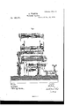
VBe it known that I, ALBIN WARTH, of Stapleton, in the county of Richmond and State of New York, have invented a new and useful Improvement in Tailors Tables, which improvement is fully set forth in the following specification, reference being had to the accompanying drawings, in which- Figure l represents a sectional plan or top view, the table-top and package-carrier having been removed to expose the working parts below. Fig. 2 is a sectional side view. Fig. 3 is a plan of the table and package-carrier. Fig. 4 is a transverse section in the plane mv, Fig. 2.
Similar letters indicate corresponding parts.
This invention relates to certain improvements on that class of tailors7 tables which I have described in my Patent N 0.149,015, dated March 24, 1874.
My present improvements consist in the combination, with the package-carrier, of packagesupportin g chains or belts, which are stretched loosely over rollers that are connected by a belt, for the purpose ot' facilitating the operation of unwindng the material from the package. With the package-supporting belts or chains and with the package-carrier are combined disks mounted on standards, which'are adjustable on the bottom plate of the packagecarrier, for the purpose of confining the packages endwise. With the table and the end gages are combined adjustable edge gages, whereby the successive layers are easily brought in the desired position, one on top of the other. With the table is combined a truck drawn by a rope or chain and a reversing-gear, so that the attendant can ride backward and forward on the side of the table to any desired distance. This reversinggear also serves to control the motion of the carriage which supports the package-carrier. On this carriage is secured a bracket, which eX- tends across the table, and which forms the support for the package-carrier, so that said bracket, together with the package-carrier, can be swung round, .and easy access is had to the package-carrier. The end gages are provided with side flanges, and with lips catching below the table, for the purpose of retaining the gages at right angles to the table. The rewinding-shaft is provided with disks, which can be adjusted to the Width of the material to be rewound.
In the drawing, the letter A designates a table, which is supported by legs B. On one edge of this table is secured a rail, a, and below this rail, on the door, is fastened a second rail, b. These two rails form the guides for an upright carriage, U, which is provided with two grooved wheels, c, that ride on the rail b, and with three rollers, d e, two of which bear on the outside and one on the inside ot' the rail a. (See Figs. l and 4.) The rollers d e are secured to a bracket, which can be raised or lowered on a standard, CO, which forms a part ot' the carriage U, so that said rollers can be adjusted to tables of dil'erent heights. The carriage G is moved by an endless belt or chain, D, stretched over pulleys e0 e0, which are mounted on shafts f fO, supported in standards fastened to the floor on the opposite ends of the table. On the shaftfis mounted a worm-wheel, g, which engages with a worm mounted on a vertical shaft, i, to which a revolving motion is imparted by a belt and pulley, as will be hereafter more fully described. On the upper end of the standard CO is secured a bracket, j, to which is secured the package-carrier E by means of a pivot, k, on which said ,packagecarrier can be turned round. This bracket is secured by a set-screw, so that the packagecarrier can be swung oli' from over the table, and that easy access can be had to the package-carrier at all times. A spring-catch, l, retains the package-carrier in the desired position. This spring-catch is operated by a rock-shaft, m, which extends through the ends of the carrier, and on each end of which is secured a crank, n, so that the spring-catch can be conveniently released from either side of the table or package-carrier. On the bottom plate of the package-carrier are secured two standards, 0 o, by means of set-screws p, which pass through slots g in their bottom anges, (see Fig. 3,) so that said standards can be readily adjusted at the desired distance apart. Each of the standards forms the bearing for a pin, r, and on the inner ends 1 of thesev pins are mounted disks s, which are adjusted to bear on the ends ot' the package contained in the carrier, so as to confine the same endwise.
The ends of the package-carrier form theV bearings for four rollers, t u, two above and two below, (see Fig. 2,) and each ot' these rollers is provided with two or more grooves, o, Fig. 3, for the reception of chains or belts w, which form a bight for the support of the package. (See Fig. 2.) The top rollers t are connected by a belt, al, and pulleys b1, and when the end of the lpackage 4is drawn out, the package, together with the chains w, revolves slowly, the package being confined endwise by the disks s, as previously stated, and thereby the operation o f unwinding the materia-l from the package is materially facilitated.
From one side of the package-carrier near its bottom extend two brackets, c1, in which are secured rods d1 e1 f1, (see Fig. 2,) which constitute the stretching and smoothing device-the material, as the same is drawn out of the package-carrier, being made to pass round said rods in the manner shown in Fig. 2, so that wrinkles or creases existing in the same are' smoothed out. 0n the top of the package-carrier, near one of the rollers t, are two brackets, ci, which form the bearings for rods dit cit, for guiding thematerial as the same is drawn out of the package-carrier.
On the table are secured gage-plates F, which are -provided with flanges F0, which bear against the edge of the table, and are provided with lips, which lap under the table, and in which are secured set-screws g1, so that by bringing the anges up against the edge of the table the gage-plates are brought in a position at right angles to the table edge, and bymeans of the set-screws said gage-plates are retained inthe required position. (See Fig. 2.) Near one edge'ofthe table is marked a scale, Fig. 3, for the purpose' of determining the distance between the gage-plates.
Each of the gage-plates is provided with a groove 71.1, for the purpose ot' facilitating the operation f cutting the material, and from each gage-'plate rise two studs, z", which serve to retain the folding and separating plate. On the top 4iiange of each gage-plate is secured an edge gage, G, by means of a set-screw, kl, which extends through a slot, Z1. (See Fig. 3.) By means ot' these edge gages the edges of the successive layers on one side` of the table can be brought to lie one exactly' over the other, the edges on the opposite side of the pile being left to take care of themselves,
since, in all textile fabrics, the width of the material is notprecisely the same throughout its entire length.
With the end gage-plates F are also combined gravit-ating dogs H, which swing on rock-shafts m1 mounted in lugs, which rise from the gage-plates. On these rock-shafts are secured arms nl, which carry weights o1,
' so that, when the dogs' are. turned down upon a layer of the material, their teeth take a-good hold, and said layer is prevented from slipping out.
- On` the backs of these dogs are secured slotted tubes 191, so that by drawing the material out over theseV tubes it can be conveniently cut, as hereinafter described, and then clamped down by means of the dogs.
From one end of the table extend two arms, g1, which form the bearings for a rewindingshaft, I. This rewinding-shaftis turned either by hand o'r by a belt and pulley; and it is provided with two disks, rl, which can be adjusted according to the width of the material to be rewound.
In forming a pile, the end of the fabric is drawn out of the package-carrier and secured on the table by placing it beneath the retaining-dog of the first or nearest end gage-plate. Then the carriage@ is caused to move to the second gage-plate, the fabric being drawn o ut and cut by drawing a knife through the groove in the gage-plate or through the slotted tube in the retaining-dog, and by means of this retaining-dog the end of the layer isl retained on the table. vIt' the fabric has a nap or a design, the carriage is moved back to the first gageplate, the package-carrier is turned on its pivot 7c, and the second layer is formed in the same manner as the first, and by following this process the naps or the designs of the successive layers all run in one and the same direction, and the layers are formed in pairs,
the two layers forming each pair being placed with their corresponding sides against each other, so that the same can be conveniently cut up into patterns for garments.
Previous to forming the fabric into a pile it is necessary to ascertain the exact length contained in a package, since packages marked to contain, say, fifty yards, many times contain only forty-six or forty-seven yards, and it' the gage-plates should be set at a distance of ive yards apart, the last layer would be several yards short, and the consequence would be that a part of the fabric would be wasted. After the package has been measured oft', I rewind the material by means of the shaft I. Then I return. the package into the carrier, adiust the gage-plates to the required distance, and form the pile as previously described.
During the operation of measuring the fabric and of forming the pile the attendant has to be constantly on the move from one end of the table to the other, and, since the tables used for these purposes necessarily must be of considerable length, it is exceedingly tiresome for the attendant to walk backward and forward on the side of the table. In order to facilitate the work I have provided a truck, J, which is provided with a seat for the attendant, and which moves on rails s1 s1 fastened to the ioor on that side of the table opposite thecarriage C. Said truck is attached to an endless rope or'chain, t1, which receives its motion from the same source that imparts motion to the carriage G, and the motion of the truck iscontrolled by a reversing-gear, which is fully illust-rated in Figs. l and 4 of the drawing. This reversing-gear consists, essentially, of a shaft, a2, on which are mounted two loose pulleys, b2 c2, and an intermediate fast pulley, cl2. K is the driving-shaft, which has its bearings in arms secured to the table A, and to which motion is imparted by means of a belt, L. On this driving-shaft is mounted a pulley, M, equal in width to the three pulleys b2 c2 d2, and from this pulley extend two belts, N O, round the pulleys b2, c2, or d2, the belt N being open and the belt O crossed, so that they vimpart motion to the pulleys b2, c2, or d2, on which they may be running in opposite directions. The position ofthe belt N is controlled by a belt-shipper, c2, and that ofV the belt o by a beltshipper,j'2.V The. belt-shippere2 connects, by a link, g2, with a lever, h2, which is mounted on a vertical rock-shaft, i2, on which is also mounted a lever, jz, which connects by a link, k2, with a rod, P, that is supported in brackets Z2 secured to two of the table-legs, said rod being free to slide and to -revolve in its bearings. rlhe belt-shipper]LIZ connects, by means of a link, m2, Vertical rockshaft n2, levers o2 p2, and link g2 with a rod, Q, which is parallel to rod P, and has a sliding and rotating motion in the brackets Z2. On the shaf't a2 is also mounted a pulley, b3, from which extends a belt, c3, round a pulley, d3, mounted on the shaft z', which carries the worm that serves to impart motion to the shaft j', which carries the drums or wheels for the endless ropes or chains D t1, which impart motion to the carriage O and to the truck I.
To the under surface of the table A is secured a plate,'R, with two cam-slots,1^2 s2, which engage with pins t2 u2 extending from sleeves, which are secured on the rods P Q by means of set-screws. On these rods are also secured latches y2 z2, and from the truck J rises a standard, a3, which acts on said latches, The latches are attached to the clamping devices, which form their connection with the rods P Q in such a manner that they-the latches-are rigid in one and yielding` in the opposite direction.
In Fig. l ofthe drawing the crossed belt O runs on the fast pulley cl2, and the truck J moves in the direction of the arrow marked on it. When the standard a3 of the truck strikes the latch z2 on the rod Q, said rod is caused to slide in its bearings, the rock-shaft n2 is caused to oscillate, and the belt-shipper f2 is moved so as to throw the belt Ofrom the fast pulley d2 on the loose pulley c2, and the motion of the truck stops. Before the motion of the truck stops, however, the pin u2 has reached the cam-shaped end of the slot s2, and thereby the latch z2 on the rod Q is turned up so that the same clears the standard of the truck. This arrangement is desirable in order to prevent-the truck from catching up against the latch z2 before the motion of the chain or rope carrying said truck has entirely ceased. `In order to reverse the motion of the truck the rod P is pushed out in the direction of the arrow marked near it in Fig.`l, whereby the belt N is thrown on the fastpulley d2. By means of the latch y2 the motion of the truck is again stopped automatically, and its motion is reversed by sliding the rod Q in the proper direction. 1
It will be seen from this description that, in the example shown in the drawing, the operation of reversing the motion of the truck is eected by moving the rods P and Q in the proper direction by hand, but, if desired, two additional latches may be applied, one to each of the rods P and Q, for the purpose of reversing the'motionof the truck automatically. As the speed with which lthe truck moves on tsrailsis precisely the same as that of the' package-carriage, the attendant from his seat on the truck is enabled to examine the material as the same'is drawn lout of the packagecarrier. He' can smooth down wrinkles, see
that the several layers be brought inthe proper position, out the material at the'propcr time, and control the motion of the packagecarriage by means of the same controls the motion of the truck.
When the fabric in the package-carrier is made up .in a folded package, the chains or belts w and their guide-rollers are dispensed with, the package is placed directly upon the bottom of the package-carrier, and a quantity of the fabric sufficient to form a layer of the pile is drawn off or unfolded before the package-carrier is set in motion. 'When rollerpackages are used, the chains or belts w are of importance, and by gearing their upper guide-rollers together the package is turned over regularly to its last end, and the danger is avoided that the package may rise up to the top of the package-carrier and catch between the guide-rods d* et. The truck J may also be used for moving packages, bundles, or other articles from one end of the table to the other.
What l claim as new, and desire to secure by Letters Patent, is
1. The combination, with the package-carrier E, of package-supporting chains or belts, passing over rollers u t, and forming a bight for the support of the package, substantially as shown and described.
2.I The combination, with the package-carrier E, package-supporting chains or belts 'w and rollers u t, of pulleys bl, and a belt, al, substantially as described, whereby a uniformmotion is imparted to the package-supporting chains or belts, and the unwinding of the package is facilitated.
3. The combination, with the package-carrier E and the package-supporting chains or belts w, of standards o, Which carry disks s, and which can be adjusted according to the gear which v Width of the package, said disks serving to confine the package endwise during the operation of unwinding, substantially as set forth.
4. The combination, with the carriage C, bracket j, and package-carrier E, of a rockshaift, on, extending through the ends of the package-carrier, and the spring catch l, Whereby said catch may bc operated fromV either side, substantially as set forth.
5. The combination, With the table A, package-carrier E, and end gages F, of the adjustable edge gages G, secured to the anges of the end gages, and serving to guide the edges of the several layers, substantially as described.
6. The combination, with the table A, package-carrier E, of the end gages F, having flanges F0, provided with lips catching beneath the table, and the slotted edge gages secured to the flanges FO ofthe end gages, as and for the purpose described.
7. The combination, with the table A, and with the carriage Which-supports the package-carrier, of a reversing-gear, substantially such as herein described, whereby the motion of the carriage can be controlled by the attendant. l
8. The combination, with the table A, carriage G, and package-carrier E, of a truck, J, moving by mechanism on rails along one side of the table, substantially as and for the purpose setforth.
9. The combination, with the table A, carriage C, package-carrier E, and truck J, of a reversing-gear, substantially as herein described, for controlling the motion of the truck and of the carriage.
10. The combination, With the table A and truck J, having standard a3, of sliding rods P Q, latches y2 y2, belt-shippers e2 f2, belts N. O, pulleys b2 c2 d2, and mechanism connecting the rods and shippers, all constructed and operating substantially as shown and described.
l1. 'Ihe combination, with the table A, truck J, having standard a3, sliding rods P Q, latches y2 y2, belt-shippers e2 f2, and mechanism connecting the rods and shippers, of a plate, R, with cam-stops r2 s2, which engage with pins t2 u2 extending from the sliding rods .P Q, substantially as and for the object set In testimony that I claim the foregoing If have hereunto set my hand this 30th day of August, 1876.
ALBIN WARTH. Witnesses:
W. HAUFF, E. F. KASTENHUBER.
Publications (1)
| Publication Number | Publication Date |
|---|---|
| US185371A true US185371A (en) | 1876-12-12 |
Family
ID=2254777
Family Applications (1)
| Application Number | Title | Priority Date | Filing Date |
|---|---|---|---|
| US185371D Expired - Lifetime US185371A (en) | Improvement in tailors tables |
Country Status (1)
| Country | Link |
|---|---|
| US (1) | US185371A (en) |
Cited By (1)
| Publication number | Priority date | Publication date | Assignee | Title |
|---|---|---|---|---|
| US2590773A (en) * | 1948-06-19 | 1952-03-25 | Katz Mortimer Ronald | Drive for cloth spreading machines |
-
0
- US US185371D patent/US185371A/en not_active Expired - Lifetime
Cited By (1)
| Publication number | Priority date | Publication date | Assignee | Title |
|---|---|---|---|---|
| US2590773A (en) * | 1948-06-19 | 1952-03-25 | Katz Mortimer Ronald | Drive for cloth spreading machines |
Similar Documents
| Publication | Publication Date | Title |
|---|---|---|
| US323792A (en) | Island | |
| US185371A (en) | Improvement in tailors tables | |
| US1499254A (en) | Cloth-rolling machine | |
| US966760A (en) | Sheet-folding machine. | |
| US207575A (en) | Improvement in tailors tables | |
| US1463717A (en) | Convertible worktable | |
| US846259A (en) | Machine for measuring and cutting cloth. | |
| US161896A (en) | Improvement in machines for tentering and straightening fabrics | |
| US431483A (en) | Gang edger | |
| US581632A (en) | Quilting attachment for sewing-machines | |
| US320031A (en) | white | |
| US357583A (en) | Apparatus for cutting and grooving fabrics | |
| US149956A (en) | Improvement in machines for matching, measuring, singeing, brushing | |
| US325581A (en) | Cloth in | |
| US466023A (en) | button | |
| US883795A (en) | Machine for making window-shades. | |
| US481933A (en) | dobeck | |
| US487352A (en) | Island | |
| US1180363A (en) | Tearing-machine. | |
| US641921A (en) | Cloth-piler. | |
| US7764A (en) | Apparatus for stretching and smoothing cloth | |
| US1085537A (en) | Machine for folding lace curtains and like materials. | |
| US396816A (en) | Machine | |
| US98308A (en) | Island | |
| US1886902A (en) | Cloth matching and measuring machine |