US1853700A - Method of making caskets by galvanoplastic process - Google Patents
Method of making caskets by galvanoplastic process Download PDFInfo
- Publication number
- US1853700A US1853700A US220945A US22094527A US1853700A US 1853700 A US1853700 A US 1853700A US 220945 A US220945 A US 220945A US 22094527 A US22094527 A US 22094527A US 1853700 A US1853700 A US 1853700A
- Authority
- US
- United States
- Prior art keywords
- mold
- metal
- anodes
- making
- casket
- Prior art date
- Legal status (The legal status is an assumption and is not a legal conclusion. Google has not performed a legal analysis and makes no representation as to the accuracy of the status listed.)
- Expired - Lifetime
Links
- 238000000034 method Methods 0.000 title description 18
- 238000004519 manufacturing process Methods 0.000 title description 11
- 239000002184 metal Substances 0.000 description 26
- 229910052751 metal Inorganic materials 0.000 description 26
- 238000000151 deposition Methods 0.000 description 12
- 230000008021 deposition Effects 0.000 description 9
- 239000008151 electrolyte solution Substances 0.000 description 7
- 230000015572 biosynthetic process Effects 0.000 description 6
- 238000009933 burial Methods 0.000 description 6
- 239000000463 material Substances 0.000 description 4
- 229910000906 Bronze Inorganic materials 0.000 description 3
- 239000010974 bronze Substances 0.000 description 3
- 239000004020 conductor Substances 0.000 description 3
- KUNSUQLRTQLHQQ-UHFFFAOYSA-N copper tin Chemical compound [Cu].[Sn] KUNSUQLRTQLHQQ-UHFFFAOYSA-N 0.000 description 3
- 239000004922 lacquer Substances 0.000 description 2
- 239000003923 scrap metal Substances 0.000 description 2
- 239000002023 wood Substances 0.000 description 2
- RYGMFSIKBFXOCR-UHFFFAOYSA-N Copper Chemical group [Cu] RYGMFSIKBFXOCR-UHFFFAOYSA-N 0.000 description 1
- 239000011248 coating agent Substances 0.000 description 1
- 238000000576 coating method Methods 0.000 description 1
- 230000000295 complement effect Effects 0.000 description 1
- 229910052802 copper Inorganic materials 0.000 description 1
- 239000010949 copper Substances 0.000 description 1
- 239000007788 liquid Substances 0.000 description 1
- 239000011159 matrix material Substances 0.000 description 1
- 239000013528 metallic particle Substances 0.000 description 1
- 238000010422 painting Methods 0.000 description 1
- 239000000843 powder Substances 0.000 description 1
- 229910000679 solder Inorganic materials 0.000 description 1
- 239000007787 solid Substances 0.000 description 1
- 239000000243 solution Substances 0.000 description 1
- 238000003466 welding Methods 0.000 description 1
Images

Classifications
-
- C—CHEMISTRY; METALLURGY
- C25—ELECTROLYTIC OR ELECTROPHORETIC PROCESSES; APPARATUS THEREFOR
- C25D—PROCESSES FOR THE ELECTROLYTIC OR ELECTROPHORETIC PRODUCTION OF COATINGS; ELECTROFORMING; APPARATUS THEREFOR
- C25D1/00—Electroforming
-
- C—CHEMISTRY; METALLURGY
- C25—ELECTROLYTIC OR ELECTROPHORETIC PROCESSES; APPARATUS THEREFOR
- C25D—PROCESSES FOR THE ELECTROLYTIC OR ELECTROPHORETIC PRODUCTION OF COATINGS; ELECTROFORMING; APPARATUS THEREFOR
- C25D1/00—Electroforming
- C25D1/02—Tubes; Rings; Hollow bodies
Definitions
- This invention relates to a method of and apparatus for making hollow articles of galvanoplastic material more particularly for the making of burial receptacles such as caskets or the like.
- One object of the invention is to provide special forms and arrangements of anodes adapted for cooperation with a mold for the making of caskets of desirable ornamental configui ation and form.
- Still another object of the invention is to provide a process for making hollow articles of galvanoplastic metal which overcomes difficulties heretofore met with in the forming of irregularly shaped articles.
- a metal mold comprising a plurality of sections which are arranged when joined to constitute an integral mold of the shape and dimensions of the article to be formed.
- the mold is constituted a container or vat for an electrolytic solution which submerges the entire receiving surface of the mold on whichthe deposition is to be made as well as the anodes which are suspended therein in a particular manner as will be hereinafter described.
- One of the principal objects of the invention is the provision of inserts such as handle brackets and hinge lugs on the galvanoplastic metal and in accordance with the invention such inserts are formed integrally with the deposited metal without the use of rivets, solder, or welding.
- the invention further contemplates the provision of apparatus which is especially adapted for the making of hollow articles of relatively large sizes such as burial caskets in an expedient and efficient manner whereby such articles may be produced in relatively large quantities in an economical manner.
- the apparatus of Fig. 1 comprises a sectional mold consisting of a base 1, side portions 2 and end portions 3, Fig. 2, which are joined at their flanged portions 4 by screw bolts 5 or in any other suitable manner to constitute a unitary mold capable of containing an electrolytic solution.
- the inner dimensions and shape of the mold are that of the outer dimensions and shape of the article to be formed and the inner surfaces or matrix of the mold on which the electrolytic solution is to be formed is of the shape and configuration desired on the outer surface of the finished article.
- the mold is further provided with depressions or recesses 6 for resuitable material.
- the anodes for convenience of handling and to permit moving them in and out of the mold are made up in sections which are ar ranged and disposed in the mold in the manner shown in Fig. 2 in which a plurality of such baskets or anodes are disposed in parallel relation along the side walls of the mold and one or more anodes are disposed in proximity with the end walls of the mold, all of the anodes being electrically connected by leads 18 to a conductor 19 constituting one leg of a source of electric currents.
- the perforated walls of the anodes adjacent the side and end walls of the mold are shaped to correspond substantially to the contour of the inner surface of the mold and as shown in Fig. 2 the lead wall sections 15 of the anodes are substantially abutting or may be so when the an odes are assembled in their working position.
- the wood frame portion 16 of the anode baskets are provided with a chamfer 20 at their edge adjacent the corners of the walls 15 to provide access of the scrap metal and the electrolytic solution to the perforations in or near the extreme edge of the perforated wall.
- the inner edges of the upper portions of the mold wall sections 2 and 3 are adapted to receive a sealer frame 23 which is temporarily held in intimate contact with the mold sections by clamping it between the frame .portion 11 and the flange 9 of the mold sections.
- a rubber liner 24 andia strip or liner 25 are secured to the mold or frame 11 as shown and are adapted to project beyond the upper edge of the mold to provide a baflie which prevents the deposition of metal on the portion of the sealer frame 23 with which the strip or liner is in contact.
- the mold is electrically connected by leads 26 to a source of electric current which constitutes the other leg of the line 19, one leg of which is connected to the anodes 13 by leads 18.
- the mold is not suspended in an electrolytic solution as commonly practiced in the making of articles by galvanoplastic process, but is preferably placed on or approximate to a separate vat or container 28 in which the elec trolytic solution is stored andfrom which it is conducted to the anodes 13 by a feed line 29v that connects to a pump 30 which is provided with outlet pipes 31 that project into the anodes.
- a return drain pipe 32 is provided which projects through the frame portion 11 on top of the mold which is the level at which the solution is maintained in the mold.
- pump 30 When current is applied to the anodes and mold, pump 30 is actuated to maintain circulation of the electrolytic solution in the mold for the duration of the process of making electrolytic deposition on the inner surface of the mold. The process is continued until a deposit of desired thickness has been made on the surface of the mold and is then interrupted by disconnecting the electric circuit from the current source.
- the mold is then dismembered by first laterally moving the anodes on their supports or supporting bars 12 to bring them together so that the lower extending portions of the anodes will clear the upper constructed portions of the mold and all of the anodes are lifted out of the mold or the mold may be lowered away from the anodes as desired.
- the sections 2 and 3 of the mold are dismembered and the finished casket which is a one piece integral member is removed.
- Figs. 3 to 6 inclusive I have illustrated in enlarged detail views portions of the mold in which inserts 7 are shown fitted in the recesses 6.
- the sealer frame 23 may be clamped by a bar 35 to the side wall 2 of the mold.
- the inserts 7 are fitted in the recesses 6 of the mold and when the body of metal 36 is deposited on the mold surface it is integrally joined to the inserts and sealer frame. This is accomplished by exposing a clean bright surface to the metal deposited thereon.
- Fig. 4 the finished article is shown after it has been removed from the mold with the inserts and sealer frameintegrally formed thereon.
- Fig. 5 I- have shown the joints of the inserts and mold bridged by powdered bronze 39.
- the lacquer in which the bronze is suspended may be applied in any suitable manner as by a brush.
- the method of making a burial casket body having galvanoplastic self-sustaining walls which comprises simultaneously depositing all sides and the bottom of said casket on the inside of a liquid-tight sectional cathode and integrally uniting a preformed metal section on the exterior of the casket 'walls during deposition with the union between said casket body and exterior section occurring on the inner side of the section.
Landscapes
- Chemical & Material Sciences (AREA)
- Engineering & Computer Science (AREA)
- Chemical Kinetics & Catalysis (AREA)
- Electrochemistry (AREA)
- Materials Engineering (AREA)
- Metallurgy (AREA)
- Organic Chemistry (AREA)
- Moulds For Moulding Plastics Or The Like (AREA)
Description
A ril 12, 1932. G. ROSENQVIST 1,853,700
METHOD OF MAKING GASKETS BY GALVANOPLASTIC' PROCESS Filed Sept. 21, 1927 3 Sheets-Sheet 1 Fly 1.
INVENTOR April 12, 1932. G. ROSENQVIST METHOD OF MAKING GASKETS BY GALVANOPLASTIC PROCESS Filed Sept. 21 1927 3 Sheets-Sheet INVENTYOR am y I ML. a
April 12, 1932. s. ROSENQVIST 1,853,700
METHOD OF MAKING GASKETS BY GALVANOPLASTIC PROCESS Filed Sept. 21, 1927 5 Sheets-Sheet 3 v INVENTOR.
fifmm 6 ATTORNEYS.
Patented Apr. 12, 1932 GUNNAR ROSENQVIST, OF PITTSBURGH, PENNSYLVANIA METHOD OF MAKE G GASKETS BY GALVANOPLASTIC PROCESS Application filed September 21, 1927. Serial No. 220,945.
This invention relates to a method of and apparatus for making hollow articles of galvanoplastic material more particularly for the making of burial receptacles such as caskets or the like.
The present application is a continuation in part of an application filed May 18, 1925 for which a Patent No. 1,711,542 was granted under date of May 7, 1929. The present in- 10 vention has among its objects the provision of special apparatus for making caskets or other hollow articles by electrolytic deposition.
One object of the invention is to provide special forms and arrangements of anodes adapted for cooperation with a mold for the making of caskets of desirable ornamental configui ation and form.
Still another object of the invention is to provide a process for making hollow articles of galvanoplastic metal which overcomes difficulties heretofore met with in the forming of irregularly shaped articles.
In carrying out my invention I utilize a metal mold comprising a plurality of sections which are arranged when joined to constitute an integral mold of the shape and dimensions of the article to be formed. In carrying out the process the mold is constituted a container or vat for an electrolytic solution which submerges the entire receiving surface of the mold on whichthe deposition is to be made as well as the anodes which are suspended therein in a particular manner as will be hereinafter described.
In the making of hollow articles of irreguQ lar shape and form by electrolytic deposition in accordance with methods heretofore practiced, it is difiicult to maintain an even current density. I have found that a substantially uniform current density conducive to the formation of deposits of substantially uniform thickness is obtained by forming the anodes or the portion of the anodes, adjacent the face or surface of the mold 011 which the deposit is to be made, complementary to the contour of the latter. -I have also found that when the mold is made with sharp intersecting faces or projections it is necessary to isolate the portion of the anodes adjacent thereto to obtain uniform current density which prevents the formation of excess metal at such portions. If such precautions are not taken, excess metal will form on the projecting portions of the mold which 5 builds up rapidly to contact with theanode resulting in a short circuit across the anode and mold.
One of the principal objects of the invention is the provision of inserts such as handle brackets and hinge lugs on the galvanoplastic metal and in accordance with the invention such inserts are formed integrally with the deposited metal without the use of rivets, solder, or welding.
The invention further contemplates the provision of apparatus which is especially adapted for the making of hollow articles of relatively large sizes such as burial caskets in an expedient and efficient manner whereby such articles may be produced in relatively large quantities in an economical manner.
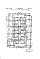
In the accompanying drawings constituting a part hereof and in which like reference characters designate like parts, Fig. 1 is a vertical sectional View of a casket mold and associated apparatus embodying the principles of my invention, Fig. 2 a top plan view thereof; Fig. 3 an enlarged view in cross-sec-' tion of a portion of the mold andfinished article illustrating the manner of holding the inserts in the mold; Fig. 4 a similar view of a portion of the completed article; and Figs. 5 and 6 are enlarged detail views in cross-section which serve to demonstrate a step in the process of forming inserts in the galvanoplastic body.
The apparatus of Fig. 1 comprises a sectional mold consisting of a base 1, side portions 2 and end portions 3, Fig. 2, which are joined at their flanged portions 4 by screw bolts 5 or in any other suitable manner to constitute a unitary mold capable of containing an electrolytic solution. The inner dimensions and shape of the mold are that of the outer dimensions and shape of the article to be formed and the inner surfaces or matrix of the mold on which the electrolytic solution is to be formed is of the shape and configuration desired on the outer surface of the finished article. The mold is further provided with depressions or recesses 6 for resuitable material.
ceiving inserts 7 which are made integral with the metal deposit on the surface of the mold to constitute ear lugs for handle brackets or the like which are attached to the casket in a manner to be hereinafter stated. The base 1 of the casket is provided with depressions 8 in spaced apart relation at the respective corners of the mold to produce excess metal for hand grips.
The mold is provided with flanges 9 extending around its upper edges for receiving clamp-bolts 10 which secure a frame 11 thereto. The frame portion 11 is provided with transverse supports 12 which project through a plurality of anodes 13 to hold the latter in proper spaced rela ion in proximity with the inner surface 0 the mold. The anodes 13 may consist of solid metal formed in the manner illustrated in Fig. 1 but are preferably perforated receptacles adapted to receive scrap metal 1a which is disposed adjacent to-a perforated wall 15 of lead or other The perforated members are secured to a frame 16 of wood or other suitable material provided with openings 17 for receiving the transverse supports 12 on which they are movably mounted.
The anodes for convenience of handling and to permit moving them in and out of the mold, are made up in sections which are ar ranged and disposed in the mold in the manner shown in Fig. 2 in which a plurality of such baskets or anodes are disposed in parallel relation along the side walls of the mold and one or more anodes are disposed in proximity with the end walls of the mold, all of the anodes being electrically connected by leads 18 to a conductor 19 constituting one leg of a source of electric currents.
As shown in Fig. 1 the perforated walls of the anodes adjacent the side and end walls of the mold are shaped to correspond substantially to the contour of the inner surface of the mold and as shown in Fig. 2 the lead wall sections 15 of the anodes are substantially abutting or may be so when the an odes are assembled in their working position. The wood frame portion 16 of the anode baskets are provided with a chamfer 20 at their edge adjacent the corners of the walls 15 to provide access of the scrap metal and the electrolytic solution to the perforations in or near the extreme edge of the perforated wall.
As shown in Fig. 1 the outer perforated Walls of the anodes are provided with isolating sections 21 of lead or other suitable material which cover up the perforations in the walls 15 adjacent the sharp projecting portions of the mold to obtain proper current density for the purpose of-preventing a direct action between the anodes and the projections of the mold.
The inner edges of the upper portions of the mold wall sections 2 and 3 are adapted to receive a sealer frame 23 which is temporarily held in intimate contact with the mold sections by clamping it between the frame .portion 11 and the flange 9 of the mold sections. A rubber liner 24 andia strip or liner 25 are secured to the mold or frame 11 as shown and are adapted to project beyond the upper edge of the mold to provide a baflie which prevents the deposition of metal on the portion of the sealer frame 23 with which the strip or liner is in contact. The mold is electrically connected by leads 26 to a source of electric current which constitutes the other leg of the line 19, one leg of which is connected to the anodes 13 by leads 18.
The mold is not suspended in an electrolytic solution as commonly practiced in the making of articles by galvanoplastic process, but is preferably placed on or approximate to a separate vat or container 28 in which the elec trolytic solution is stored andfrom which it is conducted to the anodes 13 by a feed line 29v that connects to a pump 30 which is provided with outlet pipes 31 that project into the anodes. A return drain pipe 32 is provided which projects through the frame portion 11 on top of the mold which is the level at which the solution is maintained in the mold.
When current is applied to the anodes and mold, pump 30 is actuated to maintain circulation of the electrolytic solution in the mold for the duration of the process of making electrolytic deposition on the inner surface of the mold. The process is continued until a deposit of desired thickness has been made on the surface of the mold and is then interrupted by disconnecting the electric circuit from the current source. The mold is then dismembered by first laterally moving the anodes on their supports or supporting bars 12 to bring them together so that the lower extending portions of the anodes will clear the upper constructed portions of the mold and all of the anodes are lifted out of the mold or the mold may be lowered away from the anodes as desired. The sections 2 and 3 of the mold are dismembered and the finished casket which is a one piece integral member is removed. The portions of the finished article corresponding to and which were formed in the depressions 8 of the base of the mold are pressed inwardly in a suitable manner to provide depressions in the casket at the respective corners which constitute hand grips for handling the casket in 'its manufacture. j
On account of the fact that the outer surface of the finished casket is the surface adacent the mold it will possess a smooth finish made of galvanoplastic. metal.
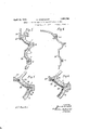
In Figs. 3 to 6 inclusive, I have illustrated in enlarged detail views portions of the mold in which inserts 7 are shown fitted in the recesses 6. As shown in Fig. 3 the sealer frame 23 may be clamped by a bar 35 to the side wall 2 of the mold. The inserts 7 are fitted in the recesses 6 of the mold and when the body of metal 36 is deposited on the mold surface it is integrally joined to the inserts and sealer frame. This is accomplished by exposing a clean bright surface to the metal deposited thereon. In Fig. 4 the finished article is shown after it has been removed from the mold with the inserts and sealer frameintegrally formed thereon.
When the deposition of copper takes place 011 the inner face of the mold and the exposed surfaces of the inserts 7 and sealer frame 23 the metal tends to form in strata. or layers and due to the small almost invisible interstices 37 at the joints of the mold and inserts a formation takes place as shown in Fig. 6 of the drawings.
' The formation has been greatly exaggerated in Fig. 6 for the purpose of illustration. Theoretically what appears to take place is that the metal as it builds up on the mold is diverted by the interstices and the successive formation of superposed layers produces a weak section 38'adj acent the joints due to crystalline growth. I have discovered that by bridging the gap as with powdered bronze or other suitable metal flakes suspended in a lacquer this tendency is overcome.
In Fig. 5 I- have shown the joints of the inserts and mold bridged by powdered bronze 39. The lacquer in which the bronze is suspended may be applied in any suitable manner as by a brush. When the body 36 is deposited on the mold and inserts the weak sections 38 d not form resulting in a product of uniform strength and quality.
It is evident from the foregoing description of my invention that the method of and apparatus for making hollow caskets as hereinbefore set forth, is simple and economical and adapted for the manufacture of caskets of pleasing and ornamental shapes and configurations. Although the invention has been illustrated as embodied in the manufacture of burial receptacles, it will be obvious to those skilled in the art that it is adapted for use generally where it is desired to form hollow articles in the manner stated and any article,
of galvanoplastic metal with inserts formed integrally therewithwithout departing from the principles herein set forth.
I claim herein as my invention:
1. The method of manufacturing metal bodiesof finely divided deposited metal hav-, ing metal inserts formed integrally therewith which comprises providing a permanent mold, placing metal inserts on the surface of the mold, bridging the gaps between the "edge in the article to be formed, and inserting a baflle between said edges of the anode and article. i 3. The process of preparing a sectional -metal mold for receiving an electrolytic deposition, which comprises filling a crack between sections of the mold with an electrically conductive material adapted to present a smooth deposit surface contiguous the filled crack.
4. The process of preparing a sectional metal mold, which comprises painting over a crack between sections with an electrically conductive material capable of filling said crack and permitting formation of a smooth deposit surface contiguous the filled crack.
5. The process of preparing a sectional metal mold for receiving an electrolytic deposit, which comprises paintingover said crack with a metal powder in a liquid vehicle.
6. The method of manufacturing a burial casket which comprises coating at least a portion of an... inner cathode surface with finely divided metallic particles and then simulta neously electro-depositing the four walls and bottom of the casket on the inside of such cathode. v
7. The method of making a burial casket body having galvanoplastic self-sustaining walls, which comprises simultaneously depositing all sides and the bottom of said casket on the inside of a liquid-tight sectional cathode and integrally uniting a preformed metal section on the exterior of the casket 'walls during deposition with the union between said casket body and exterior section occurring on the inner side of the section.
8. The method of making a burial casket body having galvanoplastic self-sustaining walls which comprises simultaneously depositing all sides and the bottom of said casket on the inside of a liquid-tight sectional cathode and integrally uniting a preformed sealer frame on the upper edge of the casket walls during deposition, with the union between said casket body and preformed sealer frame occurring on the exterior of the casket walls. In testimony'whereof, I have hereunto set my hand. f
- GUNNAR ROSENQVIST.
Priority Applications (1)
| Application Number | Priority Date | Filing Date | Title |
|---|---|---|---|
| US220945A US1853700A (en) | 1927-09-21 | 1927-09-21 | Method of making caskets by galvanoplastic process |
Applications Claiming Priority (2)
| Application Number | Priority Date | Filing Date | Title |
|---|---|---|---|
| US220945A US1853700A (en) | 1927-09-21 | 1927-09-21 | Method of making caskets by galvanoplastic process |
| GB2631928A GB322551A (en) | 1928-09-13 | 1928-09-13 | Improvements in apparatus for making caskets and like hollow articles by galvanoplastic process |
Publications (1)
| Publication Number | Publication Date |
|---|---|
| US1853700A true US1853700A (en) | 1932-04-12 |
Family
ID=26258190
Family Applications (1)
| Application Number | Title | Priority Date | Filing Date |
|---|---|---|---|
| US220945A Expired - Lifetime US1853700A (en) | 1927-09-21 | 1927-09-21 | Method of making caskets by galvanoplastic process |
Country Status (1)
| Country | Link |
|---|---|
| US (1) | US1853700A (en) |
Cited By (3)
| Publication number | Priority date | Publication date | Assignee | Title |
|---|---|---|---|---|
| US2540805A (en) * | 1946-04-30 | 1951-02-06 | John C Schwartz | Electrolytic apparatus for making radiator cores |
| US2726201A (en) * | 1950-08-02 | 1955-12-06 | Int Nickel Co | Anodic pickling and nickel plating of tank interior using single electrolyte |
| US4077864A (en) * | 1973-09-10 | 1978-03-07 | General Dynamics | Electroforming anode shields |
-
1927
- 1927-09-21 US US220945A patent/US1853700A/en not_active Expired - Lifetime
Cited By (3)
| Publication number | Priority date | Publication date | Assignee | Title |
|---|---|---|---|---|
| US2540805A (en) * | 1946-04-30 | 1951-02-06 | John C Schwartz | Electrolytic apparatus for making radiator cores |
| US2726201A (en) * | 1950-08-02 | 1955-12-06 | Int Nickel Co | Anodic pickling and nickel plating of tank interior using single electrolyte |
| US4077864A (en) * | 1973-09-10 | 1978-03-07 | General Dynamics | Electroforming anode shields |
Similar Documents
| Publication | Publication Date | Title |
|---|---|---|
| US3957593A (en) | Method of forming an abrasive tool | |
| DE3370660D1 (en) | A process of electroforming a metal product and electroformed metal product | |
| US3503856A (en) | Process for controlling electrodeposition | |
| US1853700A (en) | Method of making caskets by galvanoplastic process | |
| US3577330A (en) | Process for producing electrorefined nickel having controlled size | |
| US3649474A (en) | Electroforming process | |
| US1853747A (en) | Casket | |
| US3050115A (en) | Pulp molding suction die structure and method of making | |
| US1765320A (en) | Method and apparatus for forming molds | |
| GB322551A (en) | Improvements in apparatus for making caskets and like hollow articles by galvanoplastic process | |
| EP0022113A1 (en) | Process for electroforming objects starting from a bath containing suspended particles | |
| US2846377A (en) | Mold cavities and force plugs | |
| US2533533A (en) | Method of forming a strongly adherent electrodeposit | |
| US1931084A (en) | Mold for articles of galvanoplastic material | |
| US704399A (en) | Stained-glass window or similar object and process of making same. | |
| US2494266A (en) | Cooking utensil and method | |
| US1403903A (en) | Electroplating carbon articles | |
| US1837193A (en) | Method of electrodepositing precious metals and apparatus for practicing the same | |
| US1882522A (en) | Method of joining preformed metallic articles with alpha galvanoplastic body | |
| US1468838A (en) | Cathode for the electrolytic refing of metals | |
| US3715286A (en) | Electrorefined nickel of controlled size | |
| US2465608A (en) | Method of producing copperplated culinary vessels | |
| US1517630A (en) | Anode for use in electroplating | |
| JPS60502258A (en) | Electrodes for electrometallurgical methods | |
| US5328588A (en) | Method of inlaying metals in non-conductive materials |