US1853673A - Load discharging car - Google Patents
Load discharging car Download PDFInfo
- Publication number
- US1853673A US1853673A US260022A US26002228A US1853673A US 1853673 A US1853673 A US 1853673A US 260022 A US260022 A US 260022A US 26002228 A US26002228 A US 26002228A US 1853673 A US1853673 A US 1853673A
- Authority
- US
- United States
- Prior art keywords
- door
- doors
- car
- shaft
- hopper
- Prior art date
- Legal status (The legal status is an assumption and is not a legal conclusion. Google has not performed a legal analysis and makes no representation as to the accuracy of the status listed.)
- Expired - Lifetime
Links
Images

Classifications
-
- B—PERFORMING OPERATIONS; TRANSPORTING
- B61—RAILWAYS
- B61D—BODY DETAILS OR KINDS OF RAILWAY VEHICLES
- B61D7/00—Hopper cars
- B61D7/06—Hopper cars with openings capable of discharging both between and outside the wheels
Definitions
- Another object :o-f any invention is to ;pro-
- a still further object of :my invention is to provide improved :door nperating and lock-- ing-means whereby the door mechanisms will :13!) be self-locking and positively support the doorsqin their closed position.
- Still another object of my invention is to provide :a car ,hawing doors and door operat- .-ing devices which will .permit :of the doors being opened with their free edges -ad'jacen'tthe ao-ad hed, thus ensuring the (placement oi ballast clear of the rails, also provide for a rugged door construction which anay plow through the unload-ed ballast without lbeeonis distorted.
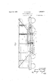
- Figure 1 is a view oi a car showing improvements incorporated there-in, the left-hand portion of the car havthe flooring removed, and certain sections of the right-hand portion being broken away .1501 the purpose of illustrating .1928. Serial No. 260,022.
- F igure2- is a longitudinalsectional view through the car, showing portions thereof in .eleva tion and is taken on a line corresponding substantially to the line 2-2 of Figure 1. 1";
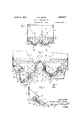
- Figure 3 is a transverse sectional viewtakon through the'caron a line corresponding substantially to a line 38 of Figure '1.
- Figure 4 is an enlarged transverse sectional view taken through the lower portion of 'the car on a line corresponding substantially to the line 4-4 of Figure '1, the inner doors beingindicated in the open position by dotted lines.
- Figure 5 is'a fractional sectional view of a portion of the car showing the parts 11 illustrated in Figure 4, with the door in .partially open position, and thedoor lifting'arm of the mechanism in engagement with the door.
- AA denotes 1v the side walls :of theca-r; B-B the sloping end walls of "the car; C the longitudinalcenter sill; D the transverse cross-tying structure; EE hopper-structures on the opposite sides ofthe-center sill; F-F transversely eX- tending hopper end walls; 1G door operating mechanism for the center doors;zH door operating mechanism for the side doors; J the l Wheels of the car; which the car rests.
- Each side wall A of the car includes side sheeting 10, side'stakes 11and l2, and upper and lower reinforcing marginal members, as indicated-at 13 and 14, respectively.
- Each sloping end wall B includes sloping end sheeting 15 flanged upwardly, as indicated at 1.6, for attachment .to the car side walls.
- KK 'therails on center sill C includes two channel members cludes a channel-shaped member 21 extending transversely from side to side of the car and is connected at each end with the car side by side gussets 22.
- On each side of the member 21 are ridge plates 23 each formed with an inclined shedding portion 123 and a vertically depending wall portion 24, the latter being made to conform to the shape of the hopper, said vertical wall portions 24 be- 111g spaced apart from each other an appreciable distance and braced by brackets 25.
- Each hopper structure E at opposite sides of the car, includes a lower if-shaped section having inner and outer discharge openings, respectively adapted to be closed by a continuous inner door 26 and a continuous outer door 27.
- each hopper on the inner side thereof is defined longitudinally by the ridge above the center sill structure C, and on the outer side by a sloping floor 28, which slopes downwardly from its adjacent side wall A.
- the lower margin of each said sheet 28 is spaced upwardly an appreciable distance from the associated outer door and reinforced by an angular-shaped member 29 furnishing a lip or margin.
- Said inner and outer doors are hinged on a common pivot center disposed below the inverted apex of the ⁇ f-shaped hopper, and which preferably consists of a longitudinally extending shaft member 30, supported in brackets 31 and 131, respectively disposed at the ends of the hopper and at the central cross-tying structure D, the doors being suitably cut away, as indicated at 32, to clear said brackets.
- the inner doors 26 are flanged at 33 concentrically with respect to the center of the shaft 30, and the rear edges of the outer doors are tangent to said concentric flange 33.
- the doors 26 and 27 are rigidiiied longitudinally by beam members 34 and 35, respectively disposed adjacent the hinge and free edges of the doors, and said doors are further braced transversely by a series of braces, as indicated at 36 and 37.
- the outer marginal edge of each inner door is deflected to present, as t 38, a suitable rigidifying means or flange for the edge of the door, said flange when the door is in closed position being adapted to abut against the inwardly directed marginal flange 120 of the center sill structure.
- the doors 26 and 27 are respectively mounted on the shaft by means of hinge brack ets 39 and 40.
- the hinges 40 on the outer doors 27 are formed of a.
- the doors 26 and 27 are each preferably adapted to extend continuously from end to end of the hopper and beneath the transverse central rigidifying structure D.
- transverse end hopper wall F which in- 1y" triangular cludes a vertical end wall plate 43, said wall adjacent the inner door 26 of the hopper being shaped to conform to the contour of the hopper, and adjacent the outer door said plate is extended beyond the outer edge of the outer door 27, as indicated at 44 in Figure 4 for the purpose of presenting a baffle plate adapted to prevent overflow of ballast at the end of the said outer door when the latter is in open position.
- Each inner door 26 is longitudinally extended at its opposite ends beyond the end Walls F of the hopper structure the projected portions increasing in extent from the hinge to the free edge of the door, thus providing a door extension, indicated at 450, projecting beyond the end wall F at each end of the door of substantialshape.
- a door extension indicated at 450
- the pair of inner doors 26 are raised and lowered in unison by means of the door operating mechanism G, which includes, for each of the inner doors 26, a longitudinally extending drawbar 46 preferably formed of inverted U-shape, having connected thereto a series of flexible connections 47, such as chains, which extend over pulley wheels 48 and are secured at their free ends to the door 26.
- the pulley wheels 48 are mounted on pivot pins 49 which extend through brackets 50 and the center sill webs.
- the bars 46 on the respective sides of the center sill are moved in unison by means of a rotary shaft 51 which extends through the center sills and is pivotally mounted therein in bearings 52, said shaft projecting toward one side of the car to permit operation thereof.
- Self-locking winding linkage mechanism connects each of the bars 46 with the said shaft 51.
- the mechanism 53 includes square hubs 54 on the shaft 51, around which wind links 55, 56, 57, 58 and 158, the latter being the terminal link member, and formed of hook shape whereby a straight line passing through the pivots at the respective ends of said terminal link member 158 will pass slightly beyond the center of the shaft 51, and lie on the far side of the axis of rotation of said shaft, when the mechanism is in locked position, thus rendering the mechanism selflocking.
- the shaft 51 is actuated fromthe side of the car by means of a worm wheel 59 ( Figures 1 and 3) and gear 60 carried at the lower part of the car side and preferably enclosed in a housing 61, said worm and gear being disposed out of the path of movement of the outer doors.
- the worm wheel 59 is preferably actuated by a short longitudinally and lading acting on the same,
- the operation of the mechanism controlling the inner doors 26 is as follows Assuming the doors to be in closed position, as indicated at the right in Figure 4, and the mechanism G positioned as in Figure 2, the operator, through the medium of shaft '62 and the worm and gear mechanism, rotates shaft 51 in a counter-clockwise direction, as viewed in Figure 2. As the shaft is rotated inanimwinding direction, the drawbar 46 is moved longitudinally, due to the weight of the, doors through the flexible connections 47. The unwinding action of the mechanism is continued until such time as the mechanism is fully released, when the inner doors will be in position, as indicated by dotted lines in Figure 4. The raising of the doors is a reversal of the door lowering operations, being accomplished by rotating the shafttl in a clockwise direction until the hooked link 158 assumes its locked position with reference to the shaft 51, which, of course, holds the doors 26 closed.
- Each of the outer doors 27 is adapted to be operated independently of the other outer door and of both inner doors 26.
- the operation of each of'said doors is through the medium of the in cchanism H.
- Each of the mechanisms H includes flexible connections, such as chains 64, adapted to wind on sheaves carried on a longitudinally eXtending shaft 66, said shaft 66 being mounted adjacent and above the free edge of the related door and supported. at the cross-tying structure in a bearing 67 carried by bracket 68 and supported at its ends by bearing members mounted on the baffle plates 44.
- each of said connections being connected .to the associated sheave 65 and to the bracket member 71 on the .door, :said member 71 being secured to the beam member 35 and extended beneath and rearwardly thereof, asindicated at 72.
- the extension 72 is adapted to receive the threaded end-73 of the flexible connection 64, whereby the length-of the connection may be'adjusted.
- the bracket 71 Adjacent the'free edge of the door, the bracket 71 is provided with members having load bearing surfaces 74 inclined with reference to the main plane of the door.
- Said bearing members 7 4 are disposed on opposite sides of the flexible connection, and in alignment with lugs 7 5 5, which are fixed relatively to, and-disposed on either side of each sheave 65' and constitute extensions thereof. ⁇ Vith the doors in closed position, the lugs 75-75., which are of armate form, engage beneath the oblique load bearing surfaces 7 4 on the door in such :a man.-
- the V door 27 is coped, as indicated at 77, for the connection to extend therein, and a sealing bracket 7 8 is disposed on the lower edge of the sloping floor 28,'in alignment with'the said cope, for the purpose of sealing said opening when the door is in closed position.
- each longitudinal shaft 66 is effected from the side of the car by a short transverse shaft 79, said shaft being operatively connected by means of worm and gearing enclosed in a housing and indicated conventionally at 80.
- the arrangement of worm and gearing for the inner and outer d'oors permits of the gradual opening of the doors whereby they may be maintained in any adjusted position and the flow of ballast controlled and limited to theexact quantities desired.
- the mounting of the doors and the proportioning of the doors in relation to the rails K eliminate the tendency to flood thetrails during the unloading of ballast, as the disposition of the adjacent hoppers to each other and to the rails I standard ratio for ballast.
- baflle plates 44 are disposed on the car structure at the ends of the outer doors 27, and a novel construction is employed for the center or inner doors 26 which provides for lengthening the doors beyond the end walls F of the hopper, whereby the material which would normally flow from the ends of the hopper is diverted and placed beyond the free edge of the doors.
- each inner door which thus projects be yond the end wall of the hopper, is of triangular formation, diverging outwardly from the hinge edge of the door towards the free edge thereof, whereby the door increases in length as the free edge is approached, thus providing a door having a greater length at its free edge than at the pivotal end thereof.
- a baffle plate 45 is preferably formed by flanging the door upwardly, said baflle lying at an angle to the end hopper wall, and formed to diverge outwardly from the hinge end theroof and also formed with its greatest depth adjacent the free edge of the door, thus providing for maximum interception of ballast at the point of greatest door opening.
- This arrangement by diverting the end flow of material from over the end of the door to the outer edge thereof, increases the length of the dumping platform, thereby allowing the ballast to spread out, and insures a more even flow of the discharging material.
- the diverging construction of the door also enables the door in any of its positions to clear the wheels J and the spacing of tne bafile plate 45 outwardly from the hopper wall permits adequate clearance beneath the sloping hopper end wall B for the reception of a baffle plate of extended depth when the door is in closed position.
- the comb nation with a longitudinally extending hopper including a transversely extending hopper end wall and a longitudinally extending door, said door in closed position being adapted to incline upwardly and inwardly and movable to a downwardly inclined position; of means for preventing the overflow of discharging material from over the end of the door and causing said material to discharge over the free edge of the door, said means including: an extension on the door projecting beyond the hopper end wall; and a baflle plate rising upwardly from said door extension, said baffle plate lying at an angle to the transverse hopper end wall.
- a longitudinally extend ng hopper including trans versely extending hopper end walls and a door extending between said hopper end walls and formed with upwardly extending baflle plates at each end thereof, said baffl'e plates extending at an angle to the hopper end walls whereby said plate will flare outwardly and be spaced away from the hopper end wall at the free edge of the door a greater distance than near the hinge end thereof.
- a hopper including a hopper end wall and pivotally mounted door projecting beyond the hopper end wall, said projecting portion of the door being formed to present increasing door area as the distance from the pivotal center of the door increases for the purpose of intercepting the flow of the load beyond the hopper end wall and directing the overflow beyond the free edge of the door and free of the rails.
- a longitudinally extending hopper having transversely extending walls at each end and a pivotally mounted door extending continuously between the end walls and projecting beyond the same, said projecting portion of the door increasing in length as the distance from the pivotal center of the door increases, whereby a triangular door platform is provided at each end of the hopper for the purpose of intercepting overflow of the load at the ends of the hopper and directing the ballast beyond the free edge of the door.
- each of said hoppers including an outer and an inner door pivoted on a common pivotal hinge center, the inner doors of the respective hoppers being adapted to be operated in unison; a transverse wall at each end of the hopper, said wall being disposed inside of the ends of the inner doors whereby the inner doors extend beyond the hopper end walls and intercept the flow of ballast issuing at the ends of the hopper and direct the same beyond the free edge of the door and free of the rails; end bafile plates on the inner doors adapted to confine the ballast on the doors, said baflie plates diverging outwardly from the hinge edge of the doors and lying at an angle to thehopper end walls.
- each said opper including a door hinged outwardly of the center sill and having its free ed e extended inwardly towards the center of tl ae car; and means for operating said doors in unison from the side of the car, said means including: a bar on each side of the center sill extending lengthwise of the car, flexible elements connecting each bar with its associated door, pulleys adapted to deflect the flexible elements from a straight line path, a winding shaft extending transversely of the car, winding connections on the respective sides of the center sills connecting the bars and transverse shaft, and means at the side of the car for actuating the transverse shaft.
- door operating means 7 disposed beneath said hood-shaped member at the side of the center sill, said means ineluding: a series of pulleys; a bar extending lengthwise of the car above the said pulleys; flexible elements connecting the bar and door,
- said means including: a transversely extending shaft; self-locking linkage winding mechanism connecting the bar and transverse shaft; and a worm and gearing for actuating the transverse shaft, sa1d worm and gearing being disposed at the side of the car.
- said means including: a longitudinally extending bar disposed at each side of the center sill; a series of pulleys disposed in alignment with each of said bars; and flexible connections extending over said pulleysand connecting the bars and doors; and means for moving the respective bars longitudinally in unison, said means includ ing a transverse shaft extending through the center sills and outwardly to the side of the,
- a door adapted nor mally to lie in an upwardly and outwardly inclined position and movable to a downwardly inclined open position with its free edge adjacent the road bed; a shaft pivotally mounted outwardly beyond the free edge of the door and below the level of same when the door is in closed position; a connection extending between said shaft and door to raise the same; and a door engaging member mov able with the shaft and adapted to engage the door at a predetermined pointfand relieve the flexible connection of the weight of the door,; said member having a curved seat adapted to seat beneaththe door.
- sheave to raise the do-or and means fixed'relatively to the sheave at an appreciable dis: tance from its center of rotation and adapted to engage with the door at a predetermined point to lift the sameabove the levelof the shaft and relievezthe flexible connectionjof the weight of. the door.
- each ofsaidr hoppers having an inner; and an outer doorhingedon a common pivotal center, raising means for theinner pair of doors ofthe respective hoppers, said-raising means includingf longitudinal 1y movable members, flexible connections ex tending between the movable members and the'doors, pulley wheels on the car structure adapted to deflect the connections from a straight-line path; and raising means for the outer doors, said raising means being adapt ed to be actuated by longitudinally extending shafts having flexible connections extending therefrom to. the respective outer doors; and worm and gearing for the said center doors arranged adjacent the side of the car and out ofthe path of the side doors and side doorraising means.
- the combination withmeans providing a dumping opening; of a door adapted to open and close said opening; and operating mechanism for said door, including: a shaft rotatably mounted adjacent the free edge of said door, said shaft being provided with a sheave having eccentric lugs thereon adapted to engage said door to lift the same when nearly closed, there being a fiexible connection between Y said sheave and said door; and worm mechanism for rotating said shaft.
- each of said hoppers having a pair of transversely movable doors for discharging material either centrally of the rails or to the outer sides of the rails; a winding shaft extending transversely of the car and operable from one side of the same, connections extending lengthwise of the car from the winding shaft to the centrally discharging doors, said connections including means for deflecting movement of the connections from a straight line path; and a longitudinally extending winding shaft for operating the outer doors, said latter winding shaft being disposed outwardly of said outer doors and having flexible extensions extending therefrom to said doors.
- each longitudinal hoppers formed of V shape, each including inner and outer movable walls, the inner walls of the respective hoppers being adapted for center discharge and outer walls for side discharge; means for independently operating the hoppers for center and side discharge, each said operating means including operating shafts and flexible connections extending from the shafts to the respective doors; one of said operating means having its flexible connections and operating shaft arranged to wind lengthwise of the car and the other of said operating means being arranged to wind transversely of the car.
- each of said hoppers having movable doors for discharging material either centrally of the rails or to the outer sides thereof, flexible connections connected to the centrally discharging doors and extending lengthwise of the doors, actuating means for said flexible connections including an operating shaft extending transversely of the car; and operating means for the side discharging doors including flexible connections extending transversely of the car and longitudinally extending operating shafts connecting there with.
Landscapes
- Engineering & Computer Science (AREA)
- Transportation (AREA)
- Mechanical Engineering (AREA)
- Power-Operated Mechanisms For Wings (AREA)
Description
April 12, 1932.
G. B. DOREY LOAD DISCHARGING CAR 3 Sheets-Sheet File d March 8,
00 a a q o a o o o u 90 o o a o o u use a u o m 0 a a o a no a a o a a o D 00 nauuaoo v 450/? am/E7 Ava/FE) W 7 7 oanoonaw 00 D (Amt,
hie-vogue April 12, 1932. G. B. DOREY 1,853,673
LOAD DISCHARGING CAR Filed March 8, 1928 3 Sheets-Sheet 2 GEORGE B/IYET 00/75) April 12 1932. DREY 1,853,673
LOAD -DI SCHARGING CAR Filed March 8, 1928 3 SheeW-Sheet 3 1 612mm; BINET 00,75)
Patented Apr. 12, 1932 ATiENT GEORGE -B. DOREY, OF EVANSTON, ILLINOIS, A'SSIGNCRYTO ENTERPRISE RAILWAY EQUIPMENT COMPANY, -OF (CHICAGO, ILLINOIS, A CORPORATION OF ILLINOIS LOAD 'DISCHARGING CAR invention relates to improvements in load discharging scars, andespecially to that type :adapted to discharge ballast between .the rails, r01 :to the .sides thereof, I or to either :one .or :both :sides simultaneously with the center. :In :cars of the identified type, it is customary to discharge the load while the trainsisinsmotion, theoperatorwalkingat the :side {Of the train while operating the doors, in :and zit is therefore essential that the door operating mechanismsionsuch cars should be :sate :and convenient in operation and pen and :of the door openings being perfectly 'zgradaiated, whereby the :doors may be held an :in any adjusted ,position rand the how of ihal'last controlled and sdischarged in thelen- :act quantities required.
It is an object of any invention to gpI'OVldB simple ca'r iof thezty pe described which will "in discharge ballast in such a manner :as to obviate tfloodingrof the rails.
Another object :o-f any invention is to ;pro-
Wide means tor deflecting the flow 'of ballast which normally [occurs at the :ends of the doors and direct the same beyond the outer edge of the .doors and clear of the @rails.
A still further object of :my invention is to provide improved :door nperating and lock-- ing-means whereby the door mechanisms will :13!) be self-locking and positively support the doorsqin their closed position.
Still another object of my invention is to provide :a car ,hawing doors and door operat- .-ing devices which will .permit :of the doors being opened with their free edges -ad'jacen'tthe ao-ad hed, thus ensuring the (placement oi ballast clear of the rails, also provide for a rugged door construction which anay plow through the unload-ed ballast without lbeeonis distorted.
35 specification, Figure 1 is a view oi a car showing improvements incorporated there-in, the left-hand portion of the car havthe flooring removed, and certain sections of the right-hand portion being broken away .1501 the purpose of illustrating .1928. Serial No. 260,022.
the interior arrangement-of the parts. F igure2-is a longitudinalsectional view through the car, showing portions thereof in .eleva tion and is taken on a line corresponding substantially to the line 2-2 of Figure 1. 1";
.Figure 3 is a transverse sectional viewtakon through the'caron a line corresponding substantially to a line 38 of Figure '1.
Figure 4 is an enlarged transverse sectional view taken through the lower portion of 'the car on a line corresponding substantially to the line 4-4 of Figure '1, the inner doors beingindicated in the open position by dotted lines. Figure 5 is'a fractional sectional view of a portion of the car showing the parts 11 illustrated in Figure 4, with the door in .partially open position, and thedoor lifting'arm of the mechanism in engagement with the door.
As shown in the drawings, AA denotes 1v the side walls :of theca-r; B-B the sloping end walls of "the car; C the longitudinalcenter sill; D the transverse cross-tying structure; EE hopper-structures on the opposite sides ofthe-center sill; F-F transversely eX- tending hopper end walls; 1G door operating mechanism for the center doors;zH door operating mechanism for the side doors; J the l Wheels of the car; which the car rests.
Each side wall A of the car includes side sheeting 10, side'stakes 11and l2, and upper and lower reinforcing marginal members, as indicated-at 13 and 14, respectively. Each sloping end wall B, includes sloping end sheeting 15 flanged upwardly, as indicated at 1.6, for attachment .to the car side walls. The
and KK 'therails on center sill C includes two channel members cludes a channel-shaped member 21 extending transversely from side to side of the car and is connected at each end with the car side by side gussets 22. On each side of the member 21 are ridge plates 23 each formed with an inclined shedding portion 123 and a vertically depending wall portion 24, the latter being made to conform to the shape of the hopper, said vertical wall portions 24 be- 111g spaced apart from each other an appreciable distance and braced by brackets 25.
Each hopper structure E, at opposite sides of the car, includes a lower if-shaped section having inner and outer discharge openings, respectively adapted to be closed by a continuous inner door 26 and a continuous outer door 27. Above the doors, each hopper on the inner side thereof is defined longitudinally by the ridge above the center sill structure C, and on the outer side by a sloping floor 28, which slopes downwardly from its adjacent side wall A. The lower margin of each said sheet 28 is spaced upwardly an appreciable distance from the associated outer door and reinforced by an angular-shaped member 29 furnishing a lip or margin. Said inner and outer doors are hinged on a common pivot center disposed below the inverted apex of the \f-shaped hopper, and which preferably consists of a longitudinally extending shaft member 30, supported in brackets 31 and 131, respectively disposed at the ends of the hopper and at the central cross-tying structure D, the doors being suitably cut away, as indicated at 32, to clear said brackets. The inner doors 26 are flanged at 33 concentrically with respect to the center of the shaft 30, and the rear edges of the outer doors are tangent to said concentric flange 33. The doors 26 and 27 are rigidiiied longitudinally by beam members 34 and 35, respectively disposed adjacent the hinge and free edges of the doors, and said doors are further braced transversely by a series of braces, as indicated at 36 and 37. The outer marginal edge of each inner door is deflected to present, as t 38, a suitable rigidifying means or flange for the edge of the door, said flange when the door is in closed position being adapted to abut against the inwardly directed marginal flange 120 of the center sill structure. The doors 26 and 27 are respectively mounted on the shaft by means of hinge brack ets 39 and 40. The hinges 40 on the outer doors 27 are formed of a. plurality of walls 4141 spaced apart from each other a suflicient distance to straddle hinge 39 on the inner door, the latter being preferably formed of a single wall 42 of appreciable thickness. The doors 26 and 27 are each preferably adapted to extend continuously from end to end of the hopper and beneath the transverse central rigidifying structure D. At each end of the base of the hopper there is disposed the transverse end hopper wall F, which in- 1y" triangular cludes a vertical end wall plate 43, said wall adjacent the inner door 26 of the hopper being shaped to conform to the contour of the hopper, and adjacent the outer door said plate is extended beyond the outer edge of the outer door 27, as indicated at 44 in Figure 4 for the purpose of presenting a baffle plate adapted to prevent overflow of ballast at the end of the said outer door when the latter is in open position. Each inner door 26 is longitudinally extended at its opposite ends beyond the end Walls F of the hopper structure the projected portions increasing in extent from the hinge to the free edge of the door, thus providing a door extension, indicated at 450, projecting beyond the end wall F at each end of the door of substantialshape. At the outer margin of each excension 450 there is formed an upwardly disposed baffle plate 45 which lies at an angle to the related hopper end wall F and outwardly of the same, thus providing increased length for the door, with the minimum length. adjacent the hinged axis of the door, and diverging to provide the maximum length along the free edge thereof.
The pair of inner doors 26 are raised and lowered in unison by means of the door operating mechanism G, which includes, for each of the inner doors 26, a longitudinally extending drawbar 46 preferably formed of inverted U-shape, having connected thereto a series of flexible connections 47, such as chains, which extend over pulley wheels 48 and are secured at their free ends to the door 26. The pulley wheels 48 are mounted on pivot pins 49 which extend through brackets 50 and the center sill webs. The bars 46 on the respective sides of the center sill are moved in unison by means of a rotary shaft 51 which extends through the center sills and is pivotally mounted therein in bearings 52, said shaft projecting toward one side of the car to permit operation thereof. Self-locking winding linkage mechanism, as indicated at 53, connects each of the bars 46 with the said shaft 51.- The mechanism 53 includes square hubs 54 on the shaft 51, around which wind links 55, 56, 57, 58 and 158, the latter being the terminal link member, and formed of hook shape whereby a straight line passing through the pivots at the respective ends of said terminal link member 158 will pass slightly beyond the center of the shaft 51, and lie on the far side of the axis of rotation of said shaft, when the mechanism is in locked position, thus rendering the mechanism selflocking. The shaft 51 is actuated fromthe side of the car by means of a worm wheel 59 (Figures 1 and 3) and gear 60 carried at the lower part of the car side and preferably enclosed in a housing 61, said worm and gear being disposed out of the path of movement of the outer doors. The worm wheel 59 is preferably actuated by a short longitudinally and lading acting on the same,
extending'shaft 62, said shaftbeing preferably provided with suitable ratchet and lever mechanism for rotating the same, as inclicated conventionally at 63.
The operation of the mechanism controlling the inner doors 26 is as follows Assuming the doors to be in closed position, as indicated at the right in Figure 4, and the mechanism G positioned as in Figure 2, the operator, through the medium of shaft '62 and the worm and gear mechanism, rotates shaft 51 in a counter-clockwise direction, as viewed in Figure 2. As the shaft is rotated inanimwinding direction, the drawbar 46 is moved longitudinally, due to the weight of the, doors through the flexible connections 47. The unwinding action of the mechanism is continued until such time as the mechanism is fully released, when the inner doors will be in position, as indicated by dotted lines in Figure 4. The raising of the doors is a reversal of the door lowering operations, being accomplished by rotating the shafttl in a clockwise direction until the hooked link 158 assumes its locked position with reference to the shaft 51, which, of course, holds the doors 26 closed.
Each of the outer doors 27 is adapted to be operated independently of the other outer door and of both inner doors 26. The operation of each of'said doors is through the medium of the in cchanism H. Each of the mechanisms H includes flexible connections, such as chains 64, adapted to wind on sheaves carried on a longitudinally eXtending shaft 66, said shaft 66 being mounted adjacent and above the free edge of the related door and supported. at the cross-tying structure in a bearing 67 carried by bracket 68 and supported at its ends by bearing members mounted on the baffle plates 44. There are preferably three flexible connections 64 to each door, each of said connections being connected .to the associated sheave 65 and to the bracket member 71 on the .door, :said member 71 being secured to the beam member 35 and extended beneath and rearwardly thereof, asindicated at 72. The extension 72 is adapted to receive the threaded end-73 of the flexible connection 64, whereby the length-of the connection may be'adjusted. Adjacent the'free edge of the door, the bracket 71 is provided with members having load bearing surfaces 74 inclined with reference to the main plane of the door. Said bearing members 7 4 are disposed on opposite sides of the flexible connection, and in alignment with lugs 7 5 5, which are fixed relatively to, and-disposed on either side of each sheave 65' and constitute extensions thereof. \Vith the doors in closed position, the lugs 75-75., which are of armate form, engage beneath the oblique load bearing surfaces 7 4 on the door in such :a man.-
ner that the outward thrust of the door under theloadsuppo-rted thereby is directed toward the axis of the'operating shaft 66, thus eliminating any tendency for the shaft to rotate or twist when the doors are in closed position.
t each of the flexible connections 64, the V door 27 is coped, as indicated at 77, for the connection to extend therein, and a sealing bracket 7 8 is disposed on the lower edge of the sloping floor 28,'in alignment with'the said cope, for the purpose of sealing said opening when the door is in closed position.
The operation of the mechanism H, assuming a door 27 to be in the openposition, as shown on the left hand half of Figure 4,- is as follows: To close the door, the shaft 66 is rotated in a counter-clockwise direction and the connection 64 winds on the sheave '65 until such time asthe laterally projecting lugs 75 come in contact with the bearing surfaces Y4 on the door, at which time the flexible connections 64 are then relieved of the weight of the door, and continuedrotation, ofthe shaft in the indicated direction causes the lever arms, as presented by the sheave lugs 75, to lift the door above the level of the shaft,
and arcuate surfaces of the lugs 7 5 wedge be-' neath the door, locking the same in tightly closed position. This arrangement provides for a self-locking mechanism, and also for lifting of the door above the level of the shaft in a simple manner,'and. thus renders unnecessary large and cumbersome brackets on the underside of the door such as would be liable to distortion by coming in contact with the unloaded ballast. The operation of each longitudinal shaft 66 is effected from the side of the car by a short transverse shaft 79, said shaft being operatively connected by means of worm and gearing enclosed in a housing and indicated conventionally at 80.
The arrangement of worm and gearing for the inner and outer d'oors, permits of the gradual opening of the doors whereby they may be maintained in any adjusted position and the flow of ballast controlled and limited to theexact quantities desired. The mounting of the doors and the proportioning of the doors in relation to the rails K eliminate the tendency to flood thetrails during the unloading of ballast, as the disposition of the adjacent hoppers to each other and to the rails I standard ratio for ballast.
In order to ensure against flooding of the rails, during ballasting, it is essential that excessive flow of ballast at the ends of the doors should be guarded against, and to this end the baflle plates 44 are disposed on the car structure at the ends of the outer doors 27, and a novel construction is employed for the center or inner doors 26 which provides for lengthening the doors beyond the end walls F of the hopper, whereby the material which would normally flow from the ends of the hopper is diverted and placed beyond the free edge of the doors. The extension 450 on each inner door which thus projects be yond the end wall of the hopper, is of triangular formation, diverging outwardly from the hinge edge of the door towards the free edge thereof, whereby the door increases in length as the free edge is approached, thus providing a door having a greater length at its free edge than at the pivotal end thereof. At each end of each door the u wardl extendin P y a baffle plate 45 is preferably formed by flanging the door upwardly, said baflle lying at an angle to the end hopper wall, and formed to diverge outwardly from the hinge end theroof and also formed with its greatest depth adjacent the free edge of the door, thus providing for maximum interception of ballast at the point of greatest door opening. This arrangement, by diverting the end flow of material from over the end of the door to the outer edge thereof, increases the length of the dumping platform, thereby allowing the ballast to spread out, and insures a more even flow of the discharging material. The diverging construction of the door also enables the door in any of its positions to clear the wheels J and the spacing of tne bafile plate 45 outwardly from the hopper wall permits adequate clearance beneath the sloping hopper end wall B for the reception of a baffle plate of extended depth when the door is in closed position.
That I claim is:
1. In a load discharging car adapted to discharge ballast adjacent the rails, the comb nation with a longitudinally extending hopper including a transversely extending hopper end wall and a longitudinally extending door, said door in closed position being adapted to incline upwardly and inwardly and movable to a downwardly inclined position; of means for preventing the overflow of discharging material from over the end of the door and causing said material to discharge over the free edge of the door, said means including: an extension on the door projecting beyond the hopper end wall; and a baflle plate rising upwardly from said door extension, said baffle plate lying at an angle to the transverse hopper end wall.
2. In a load discharging car, a longitudinally extend ng hopper including trans versely extending hopper end walls and a door extending between said hopper end walls and formed with upwardly extending baflle plates at each end thereof, said baffl'e plates extending at an angle to the hopper end walls whereby said plate will flare outwardly and be spaced away from the hopper end wall at the free edge of the door a greater distance than near the hinge end thereof.
3. In a load discharging car adapted to discharge ballast adjacent the rails, a hopper including a hopper end wall and pivotally mounted door projecting beyond the hopper end wall, said projecting portion of the door being formed to present increasing door area as the distance from the pivotal center of the door increases for the purpose of intercepting the flow of the load beyond the hopper end wall and directing the overflow beyond the free edge of the door and free of the rails.
4. In a load discharging car adapted to dis charge ballast adjacent the rails, a longitudinally extending hopper having transversely extending walls at each end and a pivotally mounted door extending continuously between the end walls and projecting beyond the same, said projecting portion of the door increasing in length as the distance from the pivotal center of the door increases, whereby a triangular door platform is provided at each end of the hopper for the purpose of intercepting overflow of the load at the ends of the hopper and directing the ballast beyond the free edge of the door.
5. In a load discharging car adapted to discharge ballast adjacent the rails, the combination with a center sill; of V-shaped hoppers on each side of the center sill, each of said hoppers including an outer and an inner door pivoted on a common pivotal hinge center, the inner doors of the respective hoppers being adapted to be operated in unison; a transverse wall at each end of the hopper, said wall being disposed inside of the ends of the inner doors whereby the inner doors extend beyond the hopper end walls and intercept the flow of ballast issuing at the ends of the hopper and direct the same beyond the free edge of the door and free of the rails; end bafile plates on the inner doors adapted to confine the ballast on the doors, said baflie plates diverging outwardly from the hinge edge of the doors and lying at an angle to thehopper end walls.
6. In a railway car, the combination with a center sill; of a longitudinal hopper disposed on each side of the center sill, each said opper including a door hinged outwardly of the center sill and having its free ed e extended inwardly towards the center of tl ae car; and means for operating said doors in unison from the side of the car, said means including: a bar on each side of the center sill extending lengthwise of the car, flexible elements connecting each bar with its associated door, pulleys adapted to deflect the flexible elements from a straight line path, a winding shaft extending transversely of the car, winding connections on the respective sides of the center sills connecting the bars and transverse shaft, and means at the side of the car for actuating the transverse shaft.
the door at an incline; door operating means 7 disposed beneath said hood-shaped member at the side of the center sill, said means ineluding: a series of pulleys; a bar extending lengthwise of the car above the said pulleys; flexible elements connecting the bar and door,
said elements extending above the pulleys;
and means for controlling the movement of said bar from a position adjacent the side of the car, said means including: a transversely extending shaft; self-locking linkage winding mechanism connecting the bar and transverse shaft; and a worm and gearing for actuating the transverse shaft, sa1d worm and gearing being disposed at the side of the car.
8; Ina railway car, the combination with centersills; of longitudinally extending hoppers disposed on the opposite sides of said center sills, each of said hoppers having an inner and an outer door hinged adjacent the lower portion of said hopper and movable in open position to present downwardly inclined load shedding platforms; means for raising the inner doors of the respective hop-.
pers in unison'and retaining'the same in a closed position, said means including: a longitudinally extending bar disposed at each side of the center sill; a series of pulleys disposed in alignment with each of said bars; and flexible connections extending over said pulleysand connecting the bars and doors; and means for moving the respective bars longitudinally in unison, said means includ ing a transverse shaft extending through the center sills and outwardly to the side of the,
ear; self-locking linkage mechanism connecting each bar with said transverse shaft; and
- worm and gearing disposed on the end of the shaft adjacent the side of the car whereby the door openings may be controlled and maintained in any adjusted position from the side of the car.
9. In a railway car, a door adapted nor mally to lie in an upwardly and outwardly inclined position and movable to a downwardly inclined open position with its free edge adjacent the road bed; a shaft pivotally mounted outwardly beyond the free edge of the door and below the level of same when the door is in closed position; a connection extending between said shaft and door to raise the same; and a door engaging member mov able with the shaft and adapted to engage the door at a predetermined pointfand relieve the flexible connection of the weight of the door,; said member having a curved seat adapted to seat beneaththe door. V
10; In a railway car having a sloping floor door adapted when injclosed position to ins cline' upwardly and outwardly from fits 'pivotalcenter and movable to a downwardly inelined position with its free edge adjacent the road bed; the combination with a winding shaft mounted in parallelism with thefree edge of "the door and disposed below the level of said door edge when in closedposition; a winding sheave carried by the shaft; a flexible connection extending betweenthe sheave andthe door, said connection being adapted to wind on. the
sheave to raise the do-or; and means fixed'relatively to the sheave at an appreciable dis: tance from its center of rotation and adapted to engage with the door at a predetermined point to lift the sameabove the levelof the shaft and relievezthe flexible connectionjof the weight of. the door.
11.? In a car If the character-described having two longitudinal hoppersformed' of eshape, each ofsaidr hoppers having an inner; and an outer doorhingedon a common pivotal center,,raising means for theinner pair of doors ofthe respective hoppers, said-raising means includingf longitudinal 1y movable members, flexible connections ex tending between the movable members and the'doors, pulley wheels on the car structure adapted to deflect the connections from a straight-line path; and raising means for the outer doors, said raising means being adapt ed to be actuated by longitudinally extending shafts having flexible connections extending therefrom to. the respective outer doors; and worm and gearing for the said center doors arranged adjacent the side of the car and out ofthe path of the side doors and side doorraising means. v
12. In arailway car, the combination with for said hoppers, said doors being transversely. movable for opening and closing sa1d hoppers; and operating means for said doors,
including: longitudinally movable drawbars i longitudinally extending hoppers; of doors connected with said doors, and a transverse- V ly extending worm operated shaft operatively connected with sa1d drawbars, the connec tions between sa1d drawbars and shaft ineluding self-locking linkage adaptedto cooperate with said shaft to lock the doors in closed position.
l3. In a railway car; the combination withmeans providing a dumping opening; of a door adapted to open and close said opening; and operating mechanism for said door, including: a shaft rotatably mounted adjacent the free edge of said door, said shaft being provided with a sheave having eccentric lugs thereon adapted to engage said door to lift the same when nearly closed, there being a fiexible connection between Y said sheave and said door; and worm mechanism for rotating said shaft.
14. In a car of the character described having two longitudinally extending hoppers formed of V-shape, each of said hoppers having a pair of transversely movable doors for discharging material either centrally of the rails or to the outer sides of the rails; a winding shaft extending transversely of the car and operable from one side of the same, connections extending lengthwise of the car from the winding shaft to the centrally discharging doors, said connections including means for deflecting movement of the connections from a straight line path; and a longitudinally extending winding shaft for operating the outer doors, said latter winding shaft being disposed outwardly of said outer doors and having flexible extensions extending therefrom to said doors.
15. In a car of the character described, the combination of two longitudinal hoppers formed of V shape, each including inner and outer movable walls, the inner walls of the respective hoppers being adapted for center discharge and outer walls for side discharge; means for independently operating the hoppers for center and side discharge, each said operating means including operating shafts and flexible connections extending from the shafts to the respective doors; one of said operating means having its flexible connections and operating shaft arranged to wind lengthwise of the car and the other of said operating means being arranged to wind transversely of the car.
16. In a railway car of the character described, the combination of two longitudinally extending hoppers formed of V-shape, each of said hoppers having movable doors for discharging material either centrally of the rails or to the outer sides thereof, flexible connections connected to the centrally discharging doors and extending lengthwise of the doors, actuating means for said flexible connections including an operating shaft extending transversely of the car; and operating means for the side discharging doors including flexible connections extending transversely of the car and longitudinally extending operating shafts connecting there with.
In witness that I claim the foregoing I have hereunto subscribed my name this 2nd day of March 1928.
. GEORGE E. DOREY.
Priority Applications (1)
| Application Number | Priority Date | Filing Date | Title |
|---|---|---|---|
| US260022A US1853673A (en) | 1928-03-08 | 1928-03-08 | Load discharging car |
Applications Claiming Priority (1)
| Application Number | Priority Date | Filing Date | Title |
|---|---|---|---|
| US260022A US1853673A (en) | 1928-03-08 | 1928-03-08 | Load discharging car |
Publications (1)
| Publication Number | Publication Date |
|---|---|
| US1853673A true US1853673A (en) | 1932-04-12 |
Family
ID=22987487
Family Applications (1)
| Application Number | Title | Priority Date | Filing Date |
|---|---|---|---|
| US260022A Expired - Lifetime US1853673A (en) | 1928-03-08 | 1928-03-08 | Load discharging car |
Country Status (1)
| Country | Link |
|---|---|
| US (1) | US1853673A (en) |
Cited By (4)
| Publication number | Priority date | Publication date | Assignee | Title |
|---|---|---|---|---|
| US2630767A (en) * | 1949-03-09 | 1953-03-10 | Entpr Railway Equipment Co | Ballast discharging car |
| US2730965A (en) * | 1952-09-24 | 1956-01-17 | Entpr Railway Equipment Co | Dump door mechanism for a railway car |
| US2836454A (en) * | 1949-10-18 | 1958-05-27 | Youngstown Steel Door Co | Transporation containers for bulk materials |
| AU2015342461B2 (en) * | 2014-11-03 | 2018-12-06 | Crrc Yangtze Co., Ltd | Engineering vehicle having ballast unloading device and ballast levelling device |
-
1928
- 1928-03-08 US US260022A patent/US1853673A/en not_active Expired - Lifetime
Cited By (4)
| Publication number | Priority date | Publication date | Assignee | Title |
|---|---|---|---|---|
| US2630767A (en) * | 1949-03-09 | 1953-03-10 | Entpr Railway Equipment Co | Ballast discharging car |
| US2836454A (en) * | 1949-10-18 | 1958-05-27 | Youngstown Steel Door Co | Transporation containers for bulk materials |
| US2730965A (en) * | 1952-09-24 | 1956-01-17 | Entpr Railway Equipment Co | Dump door mechanism for a railway car |
| AU2015342461B2 (en) * | 2014-11-03 | 2018-12-06 | Crrc Yangtze Co., Ltd | Engineering vehicle having ballast unloading device and ballast levelling device |
Similar Documents
| Publication | Publication Date | Title |
|---|---|---|
| US3187684A (en) | Rapid discharge hopper car | |
| US3583645A (en) | Conveyor-type hydraulic-powered endgate spreader | |
| US3183852A (en) | Discharge outlet assembly for hopper car | |
| US1853673A (en) | Load discharging car | |
| US987877A (en) | Dump-car. | |
| US3838649A (en) | Motor actuated railway hopper car doors | |
| US3717109A (en) | Motor actuated hopper door | |
| US1981714A (en) | Dump car | |
| US1706353A (en) | Dump car | |
| US1861153A (en) | Dump car construction | |
| US1768728A (en) | Load-discharging car | |
| US2835208A (en) | Ballast car door operating mechanism | |
| US2684642A (en) | Ballasting car | |
| US1800832A (en) | Ballast car | |
| US2150418A (en) | Load discharging car | |
| US1823029A (en) | Load discharging car | |
| US1615671A (en) | Dump car | |
| US2079392A (en) | Dump car | |
| US1803384A (en) | Door-tripping device for cars | |
| US1635251A (en) | Hopper car and the like | |
| US1314045A (en) | Hopper-car | |
| US2690140A (en) | Dump car door mechanism | |
| US1774870A (en) | Car construction | |
| US1705806A (en) | Dump-car door-operating mechanism | |
| US2730965A (en) | Dump door mechanism for a railway car |