US1853660A - Pipe-shaping machine - Google Patents
Pipe-shaping machine Download PDFInfo
- Publication number
- US1853660A US1853660A US566894A US56689431A US1853660A US 1853660 A US1853660 A US 1853660A US 566894 A US566894 A US 566894A US 56689431 A US56689431 A US 56689431A US 1853660 A US1853660 A US 1853660A
- Authority
- US
- United States
- Prior art keywords
- spindle
- piston
- collar
- pipe
- shaping
- Prior art date
- Legal status (The legal status is an assumption and is not a legal conclusion. Google has not performed a legal analysis and makes no representation as to the accuracy of the status listed.)
- Expired - Lifetime
Links
- 238000007493 shaping process Methods 0.000 title description 23
- 239000007788 liquid Substances 0.000 description 17
- 238000010276 construction Methods 0.000 description 3
- 238000012856 packing Methods 0.000 description 2
- 229910000760 Hardened steel Inorganic materials 0.000 description 1
- 238000010411 cooking Methods 0.000 description 1
- 239000002184 metal Substances 0.000 description 1
- 238000012986 modification Methods 0.000 description 1
- 230000004048 modification Effects 0.000 description 1
- 230000002093 peripheral effect Effects 0.000 description 1
Images

Classifications
-
- B—PERFORMING OPERATIONS; TRANSPORTING
- B21—MECHANICAL METAL-WORKING WITHOUT ESSENTIALLY REMOVING MATERIAL; PUNCHING METAL
- B21D—WORKING OR PROCESSING OF SHEET METAL OR METAL TUBES, RODS OR PROFILES WITHOUT ESSENTIALLY REMOVING MATERIAL; PUNCHING METAL
- B21D41/00—Application of procedures in order to alter the diameter of tube ends
- B21D41/02—Enlarging
Definitions
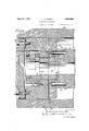
- PIPE SHAPING MACHINE Filed Oct. 5, 1931 2 Sheets-Sheet 2 Wyn/ram 1/15 HTTORWEKs Patented Apr. 12, 1932 LIONEL A. CARTER, 0F WEBSTER GROVES, MIssoum, As sIeNoR To Lnn mnn nnoirmn COMPANY, OF ST. LOUIS, MISSOURI, A CORPORATION OF MISSOURI :errn-snnrme" MACHINE Application filed. October 5,1931; Serial No. 565,894.
- This invention relates to pipe-shaping machines of the type wherein the pipeshaping' means is mounted on a rotating spindle that is moved axially by means of a nonrotating piston, and the friction between the spindle and the nonrotating piston is relieved by a liquid bearing interposed therebetween.
- the body of liquid, which forms the liquid bearing is maintained between the spindle and the. piston by contacting portions thereof.
- the spindle to deflect dueto the heavy pressure thereon, thereby causing theportions that form the seal for the liquid bearing to separate and permit the liquid to escape and thus decrease the efliciency of the bearing.
- the principal object of the present invention is to provide an arrangement which will permit such deflections of the spindle without destroying the liquid bearing between the spindle and the operating piston therefor and without causing said piston to cant or cock in the cylinder.
- Other objects are simplicity and economy of construction and compactness of design.
- the invention consists in the construction, combinations and arrangements of parts hereinafter described and claimed.
- Fig. 1 is a plan view of a portion of a pipe-shaping machine embodying my invention
- Fig. 2 is a side elevational view of the machine, partly 1n vertical longitudinalsection: V
- Fig. 3 is an enlarged fragmentary longitudinal section through the cooperating en portions of the spindle and the operating piston therefor.
- the present pipe-shaping machine comprises. a bed 1,
- a'headstock 2 having a horizontally disposed rotary and axially movable spindle 3 mounted therein which extends longitudinally of said bed; Secured to the forward end of the spindle is a face plate 4;,upon which is mounted a pipe-shap ng member in V r the form. of a combined flanglng and upsetting roller 5 adapted to engage the end of a pipev 6 to form a flange thereon.
- a pipe holder 8 provided with a. die 9, adapted to receive and shape the portlon of the pipe?) that is forced therein b'y'the rotating fian-ging roller 5.
- the pipe holder 8 is held against movement under the thrust of the fianging roller 5 by means of parallel tension rods 10. thatextend longitudinally of the machine on opposite sides thereof.
- the pipe holder 8, is secured to the tension rods 10 by means of suitable clamps 11; and said tension; rods are provided with nuts 12 that bear against the headstock 2 and prevent forward sliding movement of saidrods.
- the spindle 3 is rotated in the headstock 2 by means of 'a'worm 13 on. a cross-shaft 14, which is driven by an electric motor 15 and meshes with a worm gear 16; fixed to a shaft 17 that extends longitudinally of said spin-- dle.
- the worm gear shaft 17 is mounted in suitable bearings 18' provided therefor in the headstock 2 and is provided with a pinion 19 that meshes with a gear 20' fixed to the spindle 3.
- the pinion 19 is made wide enough so'that it will remain in mesh with the gear 20 on the spindle?) during the reci'procating' movement of the latter.
- spindle 3' is reciprocate'd in the headstock 2 by means of a piston 21 mounted ina cylinder 22 secured to the-rear end oflsaid headstock; The piston 21 is reciprocated in the cylinder 22 by means of hydraulic pressure,
- the piston 21 has an annular head'23 re- 'movably secured thereto, preferably by means-of cap screws2 i; and acup packing is clamped between the-piston and the annular head member thereof to prevent the oil from working past said piston.
- the piston 21 is preferably prevented from rotating with the spindle 3 by suitable means (not shown) so as to prevent unnecessary friction between the cylinder and the annular head and cup packing carried by said piston.
- the spindle 3 has a rear end portion 3a of reduced diameter which extends loosely through the opening in the annular head 23 of the nonrotary piston 21 and is threaded to receive a nut 25.
- the rear end of the opening in the annular piston head 23 is enlarged to accommodate the spindle nut 25, such enlarged poi tion forming a shoulder 23a against, which said nut bearsthrough a washer 26 interposed between said nut and said shoulder.
- Mounted on the reduced inner end portion 3a of the spindle 3 between the shoulder 27 thereof and the outer end of the piston head 23 are two annular members or collars 28 and 29 of hardened steel.
- the forward collar 28 is snugly fitted on the spindle 3 in abutting relation to the annular shoulder 27 thereof and terminates flush with the outer edge of said shoulder; and the rear collar 29 is a larger collar of a diameter slightly less than the diameter of the piston head 23 and has a loose fit on said spindle.
- the two collars are secured to the spindle 3 for rotation therewith by means of dowel pins 30 that have a snug fit in the spindle and in the for ward collar 28 and have a loose fit in the rear collar 29.
- the opposing faces of the two collars 28 and 29 are provided With cooperating sphericalsurfaces, the collar 28 having a convex spherical surface 28a and the collar 29 having a concave spherical surface 29a.
- the cooperating spherical surfaces 28a and 29a of the collars 28 and 29, respectively, are ground and lapped to obtain an accurate fit and the center of spherical curvature of both surfaces is located at the axis of the spindle.
- the forward end of the piston head 23 is provided at its peripheral margin with an annular rib 23?) of relatively narrow width which forms a space 31 between the opposing faces of the nonrotating piston head and the rotary spindle collar 29 adapted to receive a body of liquid, preferably oil, which forms a liquid-bearing for relieving friction between said piston head and said collar.
- the body of oil is introduced into the space 31 between the piston head and the spindle collar 29 cooperating therewith through ports 32 leading from the chamber formed b y the enlarged inner end portion of the bore in the removable piston head 23.
- the chamber is supplied with oil from the rear end of the cylinder 22 through ports 33 in the forward end of the piston.
- the spherical joint between-the collars 28 and 29 carried by the rotary spindle 3 permits the spindle to deflect or cant independently of the piston 21 and the collar 29 engaged thereby, thereby maintaining the cooperating surfaces of said collar and the annular rib 23b of said piston in contact flatwise with each other and thus preventing the body of oil, which forms the liquid seal for relieving the friction between the nonrotating piston and the rotating spindle, from escaping from the space provided therefor between said piston and said collar.
- This spherical joint also prevents cooking of the piston in the cylinder when the spindle is canted or deflected.
- a pipe-shaping machine comprising a rotary and axially slidable spindle, means on said spindle for shaping the pipe, a nonrotary piston for reciprocating said spindle, and a connection between said rotary spindle and said nonrotary piston permitting deflection of the former independently of the latter.
- a pipe-shaping machine comprising a rotary and axially slidable spindle, means on said spindle for shaping the pipe, a nonrotary piston for reciprocating said spindle, a connection between said rotary spindle and said nonrotary piston including a liquid bearing interposed between the opposing faces thereof, and means for permitting said spindle to deflect without disturbing said liquid bearing.
- a pipe-shaping machine comprising a rotary and axially slidable spindle means on said spindle for shaping the pipe, a nonrotary piston for reciprocating said spindle, a connection between said spindle and said piston including a member carried by said spin-- die for receiving the thrust of said piston, the contact surfaces of said piston and said member being limited to an annular band, thereby forming a space between said piston and said member adapted to receive a liquid, and a spherical joint between said spindle and said member permitting deflection of said spindle independently of said member.
- a pipe shaping machine comprising a rotary and axially movable spindle, a piston for reciprocating said spindle, means for connecting said spindle with said piston, said means including a collar loosely secured to '7 said spindle between the piston and an annular shoulder on said spindle, the area of contact between the opposing faces of said collar and said piston being limited to an annular band, thereby forming a space between said piston and said collar, means for supplying a liquid under pressure to said space, and means for permitting said spindle to deflect independently of said member and said piston.
- a pipe-shaping machine comprising a rotary and axially slidablespindle, means on said spindle for shaping the pipe, a nonrotatable piston for reciprocating said spindle, and a connection between said spindle and said piston permitting deflection of the former independently of the latter, said connection including a collar fixed to said spin dle, and a second collar loosely surrounding said spindle between said first-mentioned collar andsaid piston and operatively connected to said piston for rotation therewith, the opposing surfaces of said collars being shaped to form a spherical joint therebetween.
- a pipe'shaping machine comprising a rotary and axially slidable spindle, means on said spindle for shaping the pipe, a nonrotating piston for reciprocating said spindle, a connection between said spindle and said piston including a collar loosely surrounding said spindle and connected thereto for rotation therewith, a liquid seal interposed between said collar and said piston, and a joint between said spindle and said collar permitting deflection of said spindle independently of said collar.
- a pipe-shaping machine comprising a a rotary and axially slidable spindle, means on said spindle for shaping the pipe, a nonrotating piston for reciprocating said spin-- dle, a connection between said spindle and said piston including a collar rotatable with said spindle for receiving the thrust of said piston, the contact surfaces of said piston and said collar being limited to an annular band, thereby forming a space between said piston and said collar adapted to receive a liquid under pressure, and a spherical joint between said spindle and said'collar permitting defiection of said spindle independently of said collar.
- a pipe-shaping machine comprising a rotary and axially movable spindle, a piston for reciprocating said spindle, means for connecting said spindle with said piston, said means including a collar loosely secured to said spindle between the forward end of said piston and an annular shoulder on said spindle, the area of contact between the opposing faces of said collar and said piston being limited to an" annular band, thereby forming a space between said piston and said collar, means for supplying liquid under pressure to said space, and means for permitting said spindle to deflect without imparting such movement to said collar.
- a pipe-shaping machine comprising a rotary and axially slidable spindle, means on said spindle for shaping the pipe, a nonrotary piston for reciprocating said spindle, an annular head fixed to said piston, and loosely surrounding the adjacent end of said spindle, a nut on said spindle for securing the of Sept, 1931.
Landscapes
- Engineering & Computer Science (AREA)
- Mechanical Engineering (AREA)
- Joints Allowing Movement (AREA)
Description
April 12, 1932. CARTER 1,853,660
PIPE SHAPING MACHINE Filed Oct. 5, 1931 2' Sheets-Sheet l I i R April 12, 1932'. CARTER 1,853,660
PIPE SHAPING MACHINE Filed Oct. 5, 1931 2 Sheets-Sheet 2 Wyn/ram 1/15 HTTORWEKs Patented Apr. 12, 1932 LIONEL A. CARTER, 0F WEBSTER GROVES, MIssoum, As sIeNoR To Lnn mnn nnoirmn COMPANY, OF ST. LOUIS, MISSOURI, A CORPORATION OF MISSOURI :errn-snnrme" MACHINE Application filed. October 5,1931; Serial No. 565,894.
This invention relates to pipe-shaping machines of the type wherein the pipeshaping' means is mounted on a rotating spindle that is moved axially by means of a nonrotating piston, and the friction between the spindle and the nonrotating piston is relieved by a liquid bearing interposed therebetween. In such, machines the body of liquid, which forms the liquid bearing, is maintained between the spindle and the. piston by contacting portions thereof. In actual practice, there is a tendency for the spindle to deflect dueto the heavy pressure thereon, thereby causing theportions that form the seal for the liquid bearing to separate and permit the liquid to escape and thus decrease the efliciency of the bearing. These deflections of the spindle also tend to cock the piston in the cylinder, and thus further decrease the efiiciency of the machine. The principal object of the present invention is to provide an arrangement which will permit such deflections of the spindle without destroying the liquid bearing between the spindle and the operating piston therefor and without causing said piston to cant or cock in the cylinder. Other objects are simplicity and economy of construction and compactness of design. The invention consists in the construction, combinations and arrangements of parts hereinafter described and claimed.
In the accompanying drawings, which form part of this specification and wherein like symbols refer to like parts wherever they occur,
Fig. 1 is a plan view of a portion of a pipe-shaping machine embodying my invention;
Fig. 2 is a side elevational view of the machine, partly 1n vertical longitudinalsection: V
and
Fig. 3 is an enlarged fragmentary longitudinal section through the cooperating en portions of the spindle and the operating piston therefor.
Referring to the accompanying drawings, my invention is shown in connection with a machine. for flanging or otherwise shaping the: ends of the metal pipes. The present pipe-shaping machine comprises. a bed 1,
upon which is mounted a'headstock 2 having a horizontally disposed rotary and axially movable spindle 3 mounted therein which extends longitudinally of said bed; Secured to the forward end of the spindle is a face plate 4;,upon which is mounted a pipe-shap ng member in V r the form. of a combined flanglng and upsetting roller 5 adapted to engage the end of a pipev 6 to form a flange thereon.
Mounted on longitudinal slideways 7 pro-.
vided therefor on a bed 1 is a pipe holder 8 provided with a. die 9, adapted to receive and shape the portlon of the pipe?) that is forced therein b'y'the rotating fian-ging roller 5. The pipe holder 8 is held against movement under the thrust of the fianging roller 5 by means of parallel tension rods 10. thatextend longitudinally of the machine on opposite sides thereof. The pipe holder 8, is secured to the tension rods 10 by means of suitable clamps 11; and said tension; rods are provided with nuts 12 that bear against the headstock 2 and prevent forward sliding movement of saidrods.
The spindle 3 is rotated in the headstock 2 by means of 'a'worm 13 on. a cross-shaft 14, which is driven by an electric motor 15 and meshes with a worm gear 16; fixed to a shaft 17 that extends longitudinally of said spin-- dle. The worm gear shaft 17 is mounted in suitable bearings 18' provided therefor in the headstock 2 and is provided with a pinion 19 that meshes with a gear 20' fixed to the spindle 3. The pinion 19 is made wide enough so'that it will remain in mesh with the gear 20 on the spindle?) during the reci'procating' movement of the latter. spindle 3'is reciprocate'd in the headstock 2 by means of a piston 21 mounted ina cylinder 22 secured to the-rear end oflsaid headstock; The piston 21 is reciprocated in the cylinder 22 by means of hydraulic pressure,
6. preferably oil, that is supplied to the opposite ends of the cylinder through pipes orrcorrduits 22a leading from a suitable pump (not shown).
The piston 21 has an annular head'23 re- 'movably secured thereto, preferably by means-of cap screws2 i; and acup packing is clamped between the-piston and the annular head member thereof to prevent the oil from working past said piston. The piston 21 is preferably prevented from rotating with the spindle 3 by suitable means (not shown) so as to prevent unnecessary friction between the cylinder and the annular head and cup packing carried by said piston. The spindle 3 has a rear end portion 3a of reduced diameter which extends loosely through the opening in the annular head 23 of the nonrotary piston 21 and is threaded to receive a nut 25. The rear end of the opening in the annular piston head 23 is enlarged to accommodate the spindle nut 25, such enlarged poi tion forming a shoulder 23a against, which said nut bearsthrough a washer 26 interposed between said nut and said shoulder. Mounted on the reduced inner end portion 3a of the spindle 3 between the shoulder 27 thereof and the outer end of the piston head 23 are two annular members or collars 28 and 29 of hardened steel. The forward collar 28 is snugly fitted on the spindle 3 in abutting relation to the annular shoulder 27 thereof and terminates flush with the outer edge of said shoulder; and the rear collar 29 is a larger collar of a diameter slightly less than the diameter of the piston head 23 and has a loose fit on said spindle. The two collars are secured to the spindle 3 for rotation therewith by means of dowel pins 30 that have a snug fit in the spindle and in the for ward collar 28 and have a loose fit in the rear collar 29.
The opposing faces of the two collars 28 and 29 are provided With cooperating sphericalsurfaces, the collar 28 having a convex spherical surface 28a and the collar 29 having a concave spherical surface 29a. The cooperating spherical surfaces 28a and 29a of the collars 28 and 29, respectively, are ground and lapped to obtain an accurate fit and the center of spherical curvature of both surfaces is located at the axis of the spindle.
The forward end of the piston head 23 is provided at its peripheral margin with an annular rib 23?) of relatively narrow width which forms a space 31 between the opposing faces of the nonrotating piston head and the rotary spindle collar 29 adapted to receive a body of liquid, preferably oil, which forms a liquid-bearing for relieving friction between said piston head and said collar. The body of oil is introduced into the space 31 between the piston head and the spindle collar 29 cooperating therewith through ports 32 leading from the chamber formed b y the enlarged inner end portion of the bore in the removable piston head 23. The chamber is supplied with oil from the rear end of the cylinder 22 through ports 33 in the forward end of the piston.
By the arrangement described,-the spherical joint between-the collars 28 and 29 carried by the rotary spindle 3 permits the spindle to deflect or cant independently of the piston 21 and the collar 29 engaged thereby, thereby maintaining the cooperating surfaces of said collar and the annular rib 23b of said piston in contact flatwise with each other and thus preventing the body of oil, which forms the liquid seal for relieving the friction between the nonrotating piston and the rotating spindle, from escaping from the space provided therefor between said piston and said collar. This spherical joint also prevents cooking of the piston in the cylinder when the spindle is canted or deflected.
Obviously, the hereinbefore described arrangement admits of considerable modification without departing from the invention.
Therefore, I do not wish to be limited to the precise construction shown and described.
What I claim is:
1. A pipe-shaping machine comprising a rotary and axially slidable spindle, means on said spindle for shaping the pipe, a nonrotary piston for reciprocating said spindle, and a connection between said rotary spindle and said nonrotary piston permitting deflection of the former independently of the latter.
2. A pipe-shaping machine comprising a rotary and axially slidable spindle, means on said spindle for shaping the pipe, a nonrotary piston for reciprocating said spindle, a connection between said rotary spindle and said nonrotary piston including a liquid bearing interposed between the opposing faces thereof, and means for permitting said spindle to deflect without disturbing said liquid bearing.
3. A pipe-shaping machine comprising a rotary and axially slidable spindle means on said spindle for shaping the pipe, a nonrotary piston for reciprocating said spindle, a connection between said spindle and said piston including a member carried by said spin-- die for receiving the thrust of said piston, the contact surfaces of said piston and said member being limited to an annular band, thereby forming a space between said piston and said member adapted to receive a liquid, and a spherical joint between said spindle and said member permitting deflection of said spindle independently of said member.
4. A pipe shaping machine comprising a rotary and axially movable spindle, a piston for reciprocating said spindle, means for connecting said spindle with said piston, said means including a collar loosely secured to '7 said spindle between the piston and an annular shoulder on said spindle, the area of contact between the opposing faces of said collar and said piston being limited to an annular band, thereby forming a space between said piston and said collar, means for supplying a liquid under pressure to said space, and means for permitting said spindle to deflect independently of said member and said piston.
forward end of said 5. A pipe-shaping machine comprising a rotary and axially slidablespindle, means on said spindle for shaping the pipe, a nonrotatable piston for reciprocating said spindle, and a connection between said spindle and said piston permitting deflection of the former independently of the latter, said connection including a collar fixed to said spin dle, and a second collar loosely surrounding said spindle between said first-mentioned collar andsaid piston and operatively connected to said piston for rotation therewith, the opposing surfaces of said collars being shaped to form a spherical joint therebetween.
6. A pipe'shaping machine comprising a rotary and axially slidable spindle, means on said spindle for shaping the pipe, a nonrotating piston for reciprocating said spindle, a connection between said spindle and said piston including a collar loosely surrounding said spindle and connected thereto for rotation therewith, a liquid seal interposed between said collar and said piston, and a joint between said spindle and said collar permitting deflection of said spindle independently of said collar.
7. A pipe-shaping machine comprising a a rotary and axially slidable spindle, means on said spindle for shaping the pipe, a nonrotating piston for reciprocating said spin-- dle, a connection between said spindle and said piston including a collar rotatable with said spindle for receiving the thrust of said piston, the contact surfaces of said piston and said collar being limited to an annular band, thereby forming a space between said piston and said collar adapted to receive a liquid under pressure, and a spherical joint between said spindle and said'collar permitting defiection of said spindle independently of said collar.
8. A pipe-shaping machine comprising a rotary and axially movable spindle, a piston for reciprocating said spindle, means for connecting said spindle with said piston, said means including a collar loosely secured to said spindle between the forward end of said piston and an annular shoulder on said spindle, the area of contact between the opposing faces of said collar and said piston being limited to an" annular band, thereby forming a space between said piston and said collar, means for supplying liquid under pressure to said space, and means for permitting said spindle to deflect without imparting such movement to said collar.
9. A pipe-shaping machine comprising a rotary and axially slidable spindle, means on said spindle for shaping the pipe, a nonrotary piston for reciprocating said spindle, an annular head fixed to said piston, and loosely surrounding the adjacent end of said spindle, a nut on said spindle for securing the of Sept, 1931.
said spindle, a second collar loosely surrounding said spindle between said first mentioned collar and said piston, and dowel pins fixed to said spindle and loosely engaging said second collar, the contact surfaces of said piston and said secondcollar being limitedto an annular band, thereby forming a. space between said piston and said member adapted to receive a liquid under faces of said collars being providedwith concentric spherical surfaces that. permit deflection of said spindle independently of said second collar and said piston.
Signed at St. Louis, Missouri, this 26 day LIONEL A. CARTER;
pressure, the cooperating same to said piston head, a collar fixed to
Priority Applications (1)
| Application Number | Priority Date | Filing Date | Title |
|---|---|---|---|
| US566894A US1853660A (en) | 1931-10-05 | 1931-10-05 | Pipe-shaping machine |
Applications Claiming Priority (1)
| Application Number | Priority Date | Filing Date | Title |
|---|---|---|---|
| US566894A US1853660A (en) | 1931-10-05 | 1931-10-05 | Pipe-shaping machine |
Publications (1)
| Publication Number | Publication Date |
|---|---|
| US1853660A true US1853660A (en) | 1932-04-12 |
Family
ID=24264852
Family Applications (1)
| Application Number | Title | Priority Date | Filing Date |
|---|---|---|---|
| US566894A Expired - Lifetime US1853660A (en) | 1931-10-05 | 1931-10-05 | Pipe-shaping machine |
Country Status (1)
| Country | Link |
|---|---|
| US (1) | US1853660A (en) |
-
1931
- 1931-10-05 US US566894A patent/US1853660A/en not_active Expired - Lifetime
Similar Documents
| Publication | Publication Date | Title |
|---|---|---|
| US3564886A (en) | Bulging apparatus | |
| DE1039843B (en) | Swash plate pump | |
| US2610846A (en) | Packing ring | |
| DE2653868A1 (en) | HOLLOW PISTON FOR A HYDROSTATIC PISTON MACHINE AND METHOD FOR THE PRODUCTION THEREOF | |
| DE1703594B2 (en) | Axial piston pump | |
| US2461235A (en) | Fluid pressure energy translating device | |
| US2673130A (en) | Cylinder head and tube assembly | |
| DE935522C (en) | Ring-shaped sealing device for shafts, drums, etc. like | |
| US1853660A (en) | Pipe-shaping machine | |
| DE941343C (en) | Control for fluid pumps and gears | |
| DE3717517A1 (en) | EXPANDING PROBE WITH A SMALL DIAMETER AND LARGE LENGTH | |
| US1762602A (en) | Piston or plunger | |
| US2107795A (en) | Engine piston | |
| US3663072A (en) | Bearing assembly and machine using same | |
| DE1939707C3 (en) | Working cylinder for pressure medium systems | |
| US2297562A (en) | Shock absorber | |
| DE10360003A1 (en) | Piston engine, shaft and rolling bearing for a piston engine | |
| DE888206C (en) | Fluid pump or motor with cylinders arranged in a circle | |
| DE944463C (en) | bearings | |
| DE731780C (en) | Internal combustion engine | |
| DE963748C (en) | Pump or compressor | |
| US2322021A (en) | Bell | |
| DE485815C (en) | Press oil pump or motor with rotating cylinder drum and pistons working in it | |
| DE851091C (en) | Device for connecting fixed supply and discharge lines for fluids to circumferential cylindrical hollow bodies | |
| US1918852A (en) | Internal cylinder grinding tool |