US1853655A - Metal car roof - Google Patents
Metal car roof Download PDFInfo
- Publication number
- US1853655A US1853655A US482422A US48242230A US1853655A US 1853655 A US1853655 A US 1853655A US 482422 A US482422 A US 482422A US 48242230 A US48242230 A US 48242230A US 1853655 A US1853655 A US 1853655A
- Authority
- US
- United States
- Prior art keywords
- carline
- carlines
- roof
- sheets
- side plates
- Prior art date
- Legal status (The legal status is an assumption and is not a legal conclusion. Google has not performed a legal analysis and makes no representation as to the accuracy of the status listed.)
- Expired - Lifetime
Links
- 239000002184 metal Substances 0.000 title description 4
- 238000010276 construction Methods 0.000 description 10
- 230000000994 depressogenic effect Effects 0.000 description 5
- XLYOFNOQVPJJNP-UHFFFAOYSA-N water Substances O XLYOFNOQVPJJNP-UHFFFAOYSA-N 0.000 description 3
- 239000010426 asphalt Substances 0.000 description 2
- 230000003247 decreasing effect Effects 0.000 description 2
- 230000006870 function Effects 0.000 description 2
- 238000004873 anchoring Methods 0.000 description 1
- 230000004048 modification Effects 0.000 description 1
- 238000012986 modification Methods 0.000 description 1
Images
Classifications
-
- B—PERFORMING OPERATIONS; TRANSPORTING
- B61—RAILWAYS
- B61D—BODY DETAILS OR KINDS OF RAILWAY VEHICLES
- B61D17/00—Construction details of vehicle bodies
- B61D17/04—Construction details of vehicle bodies with bodies of metal; with composite, e.g. metal and wood body structures
- B61D17/08—Sides
-
- B—PERFORMING OPERATIONS; TRANSPORTING
- B61—RAILWAYS
- B61D—BODY DETAILS OR KINDS OF RAILWAY VEHICLES
- B61D17/00—Construction details of vehicle bodies
- B61D17/04—Construction details of vehicle bodies with bodies of metal; with composite, e.g. metal and wood body structures
- B61D17/12—Roofs
Definitions
- This invention relates to metal car roofs and is particularly applicable to carroofs of thetype wherein the roof sheets are movable with relation to the carlines.
- Its principal L objects are to. devise a constructionwherein the height of the carline may be reduced without sacrice of andto ⁇ better provide for the support of the sheetsand for the positioning and securing i0 of the carlines.
- the inventionj consists principally in rivetingto a main carline member of inverted channel shaped section a second member in the form of a plate with raised marginal portions that extend laterally beyond the sides of the rst member into position to support the side portions of the roof sheets.
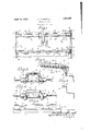
- Fig. l is a plan view of a portionof a roof 3( embodying myinvention, one vof the seam caps being removed
- v Fig'. 2 is a vertical sectional view ,crosswise of the roof on the line 12-2 of Fig. l
- Fig. 3 is a vertical section through the seam construction on the line 3-3 ofvFigs. -1 and 2
- Fig.4 is a vertical section'on the linelof Figs. 1 and 2
- - Fig. 5 is a side view ⁇ of part of a side plate with the sheetand carline supports in place thereon'but with the roof sheets and carlines removed;
- the present construction comprises side ⁇ plates l'of Z-section with vthe inner leg 2 upstanding and having riveted flatwise against he outer side ⁇ of said legfan angle shaped member 3 (or a series of angle shaped strength or headroom ved form of side plate with the carline seat Y members) whose upper leg l extends inwardly over the top of the side plate atan angle conforming to the pitch of the roof and at the proper elevation for the end portions ofv the roof sheets 5 to rest upon.
- suchangle support 3 has depressions 6 in its top of proper shape to receive and form seats for the ends of the carlines 7 which are riveted thereto. Such seats are deep enough to bring the tops of the eaves portions of the carlines to the height desired.
- the carlines are made of two members each.
- the upper member 8 is in the form of an inverted channel with outturned horizontal flanges at the bottom-s of their sides, the
- the lower carline member is in the for-m of a plate that extends the full length of the carline and is riveted to the bottom iianges of said inverted channel member.
- This bottom member is wider than the upper member of the carline and has its marginal portions struck up beyond the margins ofthe inverted channel shaped member into the form of raised horizontal flanges 10 that are of proper height for ythe side marginal por- Y tions of the roof sheets to rest upon.
- the side marginal portions of the roof sheets beyond such supports are pressedup into raised panels 11 that incline upwardly and outwardly and terminate in vertical flanges 12 at their side edges.
- the adjacent side flanges of adjacent sheets line on opposite sides ofthe upper or channel shaped member of the carline at a sufficient distance therefrom to afford adequate clearance to provide for thev distortions of the substructure.
- transverse seam cap 13 of inverted Achannel shape with laterally extending flanges at the bottoms thereof that are inclined conformably to the inclination of the inclined marginal portions ofthe roof sheets, such inclined portions of thesheets and of the seam cap being in contact andthe vertical portions of the carline cap being spaced from the vertical ianges of the sheets far enough to afford proper clearance.
- a hole 14 is formed in the bottom member of the carline immediately below the point atwhich the carline cap is secured to the upper or channel member of the carline, such hole being provided to facilitate riveting.
- the edge 15 of such hole isflanged or wingedup to prevent any water that may reach the top of said bottom member from passing through said hole. Any water that gets under the roof sheet onto said bottom member of the carline'will drain lengthwise of the paneled bottom plate and be delivered over the carline to the outside of the car.
- the carline construction hereinbefore described functions after the manner of a hollow box girder; and has important advantages in addition to its strength in carrying vertical load.
- One advantage is that, for equal strength, it requires less depth at the ridge than carlines now in use, in consequence of which the head room of the car may be increased, or the height of the roof may be decreased.
- the carline construction has the merit of maintaining the box girder section from the ridge of the car to the supports on which the ends of the carlines rest, thus greatly increasing the strength and stiffness of the carline in the region of the eaves in comparison with metal carlines now in use.
- the Z-shaped side plate has an extra inwardly extending flange 16 at its top and integral with it.
- the ends of the roof sheet rest on top of this extra flange 16 and the ends of the carlines rest in depressions or seats 17 provided therefor in the top of said extra ange and at proper intervals.
- a car roof construction comprising side plates, carlines supported by said side plates and roof sheets movably supported on said side plates and carlines, a carline comprising an upper member of inverted channel shape and a bottom member secured thereto and comprising a channel of suiicient width to receive the upper member and raised marginal panels adapted to support the roof sheets.
- a car roof constructionV comprising side plates having inwardlyextending and de-r pressed carline seats at the tops thereof, carlines supported in said seats and roof sheets movably supported on said side plates and carlines, a carline comprising an upper member of inverted channel shape and a bottom member secured thereto and comprisingV a channel of sufficient width to receive the upper member and raised marginal panels adapted to support the roofl sheets.
- a car roof construction comprising Z-shaped side plates arranged with their webs horizontal and the inner flange extending upwardly and having inwardly extending carline supports at the top thereof, said supports having depressed seats for the carlines, carlines secured in said depressed seats, and movably mounted roof sheets, the car; lines being of hollow box section throughout their length.
- a car roof construction comprising Z-shaped side plates arranged with their webs horizontal and the inner flange extending upwardly. and having inwardly extending carline supports at the top thereof, said supports comprising angle shaped members secured flatwise against the outside of the side plates and having legs that extend inwardly over the tops of the side plates and having depressed seats for the'carlines, carlines secured in said depressed seats, and movably mounted roof sheets, the carlines being of hollow box section throughout their length.
- a car roof construction comprising side plates, carlines ofhollow box section supported by said side plates and having side marginal extensions below the tops thereof constituting supports forthe roof sheets, roof sheets movably supported on said carline extensions and provided with upstanding flangesat their side edges spaced from the sides of the carlines, and a seam cover of inverted channel shape secured to each carline with its sides enclosing and spaced from the side flanges of adjacent sheets.
- a car roof construction comprising plates, ported by said side plates and having side marginal extensions below the tops thereof constituting supports for the roof sheets, roof sheets movably supported on said carline extensions and provided with upstanding flanges at their side edges spaced from the sides of the carlines and a seam cover of inverted channel shape riveted to the top of each carline with its sides enclosing and spaced from the side flanges of adjacent sheets, the lower member of the carline having a winged hole in vertical alinement with the seam cover rivet hole.
- a car roof construction comprising side side plates having inwardly extending and depressed carline seats at the tops thereof carlines supported in said seats and roof sheets movably supported on said side plates, and carlines, a carline comprising an upper member of inverted channel shape and a bottom member secured thereto and comprising a channel of sufficient width to receive the upper member and raised marginal panels adapted to support the roof sheets, the spaces at the side edges of the bottom carline members between their seats and the roof: sheets being chinked with asphaltum or the like.
Landscapes
- Engineering & Computer Science (AREA)
- Life Sciences & Earth Sciences (AREA)
- Wood Science & Technology (AREA)
- Mechanical Engineering (AREA)
- Tents Or Canopies (AREA)
Description
April 12, 1932. c. D. BONSALL.
METAL CAR ROOF Filedsept. 17, 195o lill/111114711171111 'IIIIIIIII Patented Apr. 12, 1932 UNITED vSTATES CHARLES DAVID BoNsALI'., or PITTSBURGH, rENNsYnvANIA,
PATENT OFFICEl ASSIGNOR TO IP. H. .MUR-
PHY COMPANY, 0F NEW KENSINGTON, PENNSYLVANIA, A'CORPORATION OF PENN- SYLVANA YMETAL GAR ROOF Application filed September17, 1930. Serial No. 482,422.
This invention relates to metal car roofs and is particularly applicable to carroofs of thetype wherein the roof sheets are movable with relation to the carlines. Its principal L objects are to. devise a constructionwherein the height of the carline may be reduced without sacrice of andto `better provide for the support of the sheetsand for the positioning and securing i0 of the carlines. The inventionjconsists principally in rivetingto a main carline member of inverted channel shaped section a second member in the form of a plate with raised marginal portions that extend laterally beyond the sides of the rst member into position to support the side portions of the roof sheets. It also consists in providing the side plates with angle members that serve as supports for the end portions of the roof sheets and have pockets located and arranged to receive the ends of the carlines which are riveted thereto. kIt also consists in the arrangements'and combinations of Aparts hereinafter describedand claimed.
In the accompanying drawings. which form part of this specification and wherein like numerals refer to like-parts Lwherever they occur, g `l Fig. lis a plan view of a portionof a roof 3( embodying myinvention, one vof the seam caps being removed, v Fig'. 2 is a vertical sectional view ,crosswise of the roof on the line 12-2 of Fig. l, Fig. 3 is a vertical section through the seam construction on the line 3-3 ofvFigs. -1 and 2, Fig.4 is a vertical section'on the linelof Figs. 1 and 2, v
- Fig. 5 is a side view` of part of a side plate with the sheetand carline supports in place thereon'but with the roof sheets and carlines removed; and
' Fig. 6 vis a cross .sectional view of `a modimade integral therewith. -f
' The present construction comprises side `plates l'of Z-section with vthe inner leg 2 upstanding and having riveted flatwise against he outer side `of said legfan angle shaped member 3 (or a series of angle shaped strength or headroom ved form of side plate with the carline seat Y members) whose upper leg l extends inwardly over the top of the side plate atan angle conforming to the pitch of the roof and at the proper elevation for the end portions ofv the roof sheets 5 to rest upon. At suitable intervals, suchangle support 3 has depressions 6 in its top of proper shape to receive and form seats for the ends of the carlines 7 which are riveted thereto. Such seats are deep enough to bring the tops of the eaves portions of the carlines to the height desired. f
The carlines are made of two members each. The upper member 8 is in the form of an inverted channel with outturned horizontal flanges at the bottom-s of their sides, the
channel feature and the horizontalV flanges being maintained continuously from one endk of the carline to the other end, but the` channel being of maximum depth at the ridge of the car and decreasing continuously toits ends. The lower carline member?) is in the for-m of a plate that extends the full length of the carline and is riveted to the bottom iianges of said inverted channel member. This bottom member is wider than the upper member of the carline and has its marginal portions struck up beyond the margins ofthe inverted channel shaped member into the form of raised horizontal flanges 10 that are of proper height for ythe side marginal por- Y tions of the roof sheets to rest upon. Y
The side marginal portions of the roof sheets beyond such supports are pressedup into raised panels 11 that incline upwardly and outwardly and terminate in vertical flanges 12 at their side edges. The adjacent side flanges of adjacent sheets line on opposite sides ofthe upper or channel shaped member of the carline at a sufficient distance therefrom to afford adequate clearance to provide for thev distortions of the substructure. Above the upper member of the carline and riveted thereto is a transverse seam cap 13 of inverted Achannel shape with laterally extending flanges at the bottoms thereof that are inclined conformably to the inclination of the inclined marginal portions ofthe roof sheets, such inclined portions of thesheets and of the seam cap being in contact andthe vertical portions of the carline cap being spaced from the vertical ianges of the sheets far enough to afford proper clearance.
A hole 14 (or holes) is formed in the bottom member of the carline immediately below the point atwhich the carline cap is secured to the upper or channel member of the carline, such hole being provided to facilitate riveting. The edge 15 of such hole isflanged or wingedup to prevent any water that may reach the top of said bottom member from passing through said hole. Any water that gets under the roof sheet onto said bottom member of the carline'will drain lengthwise of the paneled bottom plate and be delivered over the carline to the outside of the car.
The carline construction hereinbefore described functions after the manner of a hollow box girder; and has important advantages in addition to its strength in carrying vertical load. One advantage is that, for equal strength, it requires less depth at the ridge than carlines now in use, in consequence of which the head room of the car may be increased, or the height of the roof may be decreased. Again, the carline construction has the merit of maintaining the box girder section from the ridge of the car to the supports on which the ends of the carlines rest, thus greatly increasing the strength and stiffness of the carline in the region of the eaves in comparison with metal carlines now in use. Likewise, extending the carlines and sheet supporting' members inwardly from the side plates reduces the space that such carlines and sheets have to span, and such supporting members funct-ion as gussets for anchoring the carlines to the side plates. Another important advantage of thus supporting the roof sheets is that it substantially excludes the sunlight which, in some designs of flexible roof, has entered at the ends of the carlines and done more or less damage to the lading. In the present design, the sunlight may be more eectually excluded by chinking with heavy asphaltum or the like, the small spaces 18 at the side edges of the lower member of the carline and between the carline seat and roof sheets. Another advantage, as stated above, is that any water that may leak past the roof sheets will be drained over the side of the car.
In the modification illustrated in Fig. 6, there are no separate supporting membrs but the Z-shaped side plate has an extra inwardly extending flange 16 at its top and integral with it. The ends of the roof sheet rest on top of this extra flange 16 and the ends of the carlines rest in depressions or seats 17 provided therefor in the top of said extra ange and at proper intervals.
Ihile I have illustrated my invention as applied to a roof with movably mounted sheets, it is obvious that some of its features are applicableto roofs whose sheets are not movable relatively to each other on the substructure. For instance, the hollow box design of carline and the manner of seating and supporting the carlines and sheets may be used with non-movable sheets.
The hereinbefore described carline is the subject matter of a divisional application Serial No. 558,191, filed August 20, 1931; and the hereinbefore described side plate is the subject matter of a divisional application Serial No. 589,607, filed January 29, 1932.
What I claim is:
1. A car roof construction comprising side plates, carlines supported by said side plates and roof sheets movably supported on said side plates and carlines, a carline comprising an upper member of inverted channel shape and a bottom member secured thereto and comprising a channel of suiicient width to receive the upper member and raised marginal panels adapted to support the roof sheets.
2. A car roof constructionV comprising side plates having inwardlyextending and de-r pressed carline seats at the tops thereof, carlines supported in said seats and roof sheets movably supported on said side plates and carlines, a carline comprising an upper member of inverted channel shape and a bottom member secured thereto and comprisingV a channel of sufficient width to receive the upper member and raised marginal panels adapted to support the roofl sheets.
3. A car roof construction comprising Z-shaped side plates arranged with their webs horizontal and the inner flange extending upwardly and having inwardly extending carline supports at the top thereof, said supports having depressed seats for the carlines, carlines secured in said depressed seats, and movably mounted roof sheets, the car; lines being of hollow box section throughout their length.
4. A car roof construction comprising Z-shaped side plates arranged with their webs horizontal and the inner flange extending upwardly. and having inwardly extending carline supports at the top thereof, said supports comprising angle shaped members secured flatwise against the outside of the side plates and having legs that extend inwardly over the tops of the side plates and having depressed seats for the'carlines, carlines secured in said depressed seats, and movably mounted roof sheets, the carlines being of hollow box section throughout their length.
5. A car roof construction comprising side plates, carlines ofhollow box section supported by said side plates and having side marginal extensions below the tops thereof constituting supports forthe roof sheets, roof sheets movably supported on said carline extensions and provided with upstanding flangesat their side edges spaced from the sides of the carlines, and a seam cover of inverted channel shape secured to each carline with its sides enclosing and spaced from the side flanges of adjacent sheets.
6. A car roof construction comprising plates, ported by said side plates and having side marginal extensions below the tops thereof constituting supports for the roof sheets, roof sheets movably supported on said carline extensions and provided with upstanding flanges at their side edges spaced from the sides of the carlines and a seam cover of inverted channel shape riveted to the top of each carline with its sides enclosing and spaced from the side flanges of adjacent sheets, the lower member of the carline having a winged hole in vertical alinement with the seam cover rivet hole.
7. A car roof construction comprising side side plates having inwardly extending and depressed carline seats at the tops thereof carlines supported in said seats and roof sheets movably supported on said side plates, and carlines, a carline comprising an upper member of inverted channel shape and a bottom member secured thereto and comprising a channel of sufficient width to receive the upper member and raised marginal panels adapted to support the roof sheets, the spaces at the side edges of the bottom carline members between their seats and the roof: sheets being chinked with asphaltum or the like.
Signed at New Kensington, Pennsylvania, this 8th day of September, 1930.
CHARLES DAVID BONSALL.
carlines of hollow box section sup-
Priority Applications (3)
| Application Number | Priority Date | Filing Date | Title |
|---|---|---|---|
| US482422A US1853655A (en) | 1930-09-17 | 1930-09-17 | Metal car roof |
| US558191A US1853797A (en) | 1930-09-17 | 1931-08-20 | Carline |
| US589697A US1989264A (en) | 1930-09-17 | 1932-01-29 | Side plate for freight cars |
Applications Claiming Priority (1)
| Application Number | Priority Date | Filing Date | Title |
|---|---|---|---|
| US482422A US1853655A (en) | 1930-09-17 | 1930-09-17 | Metal car roof |
Publications (1)
| Publication Number | Publication Date |
|---|---|
| US1853655A true US1853655A (en) | 1932-04-12 |
Family
ID=23916005
Family Applications (1)
| Application Number | Title | Priority Date | Filing Date |
|---|---|---|---|
| US482422A Expired - Lifetime US1853655A (en) | 1930-09-17 | 1930-09-17 | Metal car roof |
Country Status (1)
| Country | Link |
|---|---|
| US (1) | US1853655A (en) |
-
1930
- 1930-09-17 US US482422A patent/US1853655A/en not_active Expired - Lifetime
Similar Documents
| Publication | Publication Date | Title |
|---|---|---|
| US1853655A (en) | Metal car roof | |
| US2204348A (en) | Freight car construction | |
| US2100126A (en) | Hatch construction | |
| US1853797A (en) | Carline | |
| US2034081A (en) | Car roof | |
| US1821904A (en) | Car roof | |
| US2106988A (en) | Car roof structure | |
| US1724745A (en) | Car roof | |
| US2335383A (en) | Car roof | |
| US2198430A (en) | Running board construction for car roofs | |
| US2092293A (en) | Car roof | |
| US1901008A (en) | Railway car | |
| US2256309A (en) | Car roof | |
| US1853656A (en) | Car roof | |
| US1853796A (en) | Car roof | |
| US1597047A (en) | Car roof | |
| US1553926A (en) | Flexible car roof | |
| US2120349A (en) | Car roof | |
| US2092277A (en) | Freight car construction | |
| US2236667A (en) | Hatch construction | |
| US1133493A (en) | Car-roof. | |
| US1846821A (en) | Freight car construction | |
| US1915773A (en) | Car roof | |
| US1870398A (en) | Car roof | |
| US1937309A (en) | Car roof |