US1853638A - Depilatory apparatus - Google Patents
Depilatory apparatus Download PDFInfo
- Publication number
- US1853638A US1853638A US469176A US46917630A US1853638A US 1853638 A US1853638 A US 1853638A US 469176 A US469176 A US 469176A US 46917630 A US46917630 A US 46917630A US 1853638 A US1853638 A US 1853638A
- Authority
- US
- United States
- Prior art keywords
- bar
- cables
- frame
- cable
- depilatory apparatus
- Prior art date
- Legal status (The legal status is an assumption and is not a legal conclusion. Google has not performed a legal analysis and makes no representation as to the accuracy of the status listed.)
- Expired - Lifetime
Links
- 230000002951 depilatory effect Effects 0.000 title description 7
- 239000000945 filler Substances 0.000 description 4
- 239000011810 insulating material Substances 0.000 description 4
- 229920001342 Bakelite® Polymers 0.000 description 2
- 244000261422 Lysimachia clethroides Species 0.000 description 2
- 239000004637 bakelite Substances 0.000 description 2
- 238000009413 insulation Methods 0.000 description 2
- 239000002184 metal Substances 0.000 description 2
- 102000004726 Connectin Human genes 0.000 description 1
- 108010002947 Connectin Proteins 0.000 description 1
- 239000000969 carrier Substances 0.000 description 1
- 238000010276 construction Methods 0.000 description 1
- 238000005868 electrolysis reaction Methods 0.000 description 1
- 239000000463 material Substances 0.000 description 1
Images

Classifications
-
- C—CHEMISTRY; METALLURGY
- C14—SKINS; HIDES; PELTS; LEATHER
- C14B—MECHANICAL TREATMENT OR PROCESSING OF SKINS, HIDES OR LEATHER IN GENERAL; PELT-SHEARING MACHINES; INTESTINE-SPLITTING MACHINES
- C14B1/00—Manufacture of leather; Machines or devices therefor
-
- C—CHEMISTRY; METALLURGY
- C14—SKINS; HIDES; PELTS; LEATHER
- C14B—MECHANICAL TREATMENT OR PROCESSING OF SKINS, HIDES OR LEATHER IN GENERAL; PELT-SHEARING MACHINES; INTESTINE-SPLITTING MACHINES
- C14B2700/00—Mechanical treatment or processing of skins, hides or leather in general; Pelt-shearing machines; Making driving belts; Machines for splitting intestines
- C14B2700/28—Processes or apparatus for the mechanical treatment of hides or leather not provided for in groups C14B2700/01 - C14B2700/27
Definitions
- ROSENBERG DEPILATORY APPARATUS Filed July 19, 1930 2 Sheets-Sheet l ll IHHHHi awumxbo'c Samuel ifasenk gf afloat Luz April 12, 1932- s.
- ROSENBERG DEPILATORY APPARATUS Filed July 19 1930 2 Sheets-Sheet 2 Patented Apr. 12, 1932 SAMUEL ROSENBERG, OF BROOKLYN, NEW YORK DEIILATORY APPARATUS Application filed July 19, 1930. Serial No.- 469,176.
- This invention relates to improvements in electrolysis or depilatory apparatus partic ularly to apparatus of the type described 1n Patent No. 1,445,961, of February 20th, 1923, and it is the principal object of my invention to improve the apparatus disclosed in sald patent by guiding the cables in one strand from the batteries contained in a casing through a gooseneck arrangement allowing a movement of the cable carriers into any desired position and not obscuring the instrument board.
- a further object of my invention is the provision of a hollow cable carrying and dlstributing arm to which the single cable from the battery is lead through the gooseneck.
- a further object of my invention is the provision of a plurality of cable guides on the front arm of a frame constituted by grooved bakelite rollers in the grooves of which the cables are guided.
- a still further object of my invention is the provision of a cabinet, provided with an upper housing open at the rear for the re V sisting of outer side rods 34 to the inner ends ception of the conveniently exchangeable batteries.
- Fig. 1 is a front elevation of a depilatory apparatus constructed according to my invention.
- Fig. 2 is a side elevation thereof.
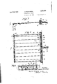
- Fig. 3 is a sectional side elevation of one of the cable guide arms, the section being taken on line 33 of Figure 4.
- Fig. 4 is a top plan view of the cable guide, partly in section on line 44 of Figure 3.
- Fig. 5 is a fragmentary front elevation of one of the cable guide arms, the front plate being removed. 7
- a cabinet 10 on legs 11 has its front closed by a hinged door 12 and lock 13.
- the cabinet carries an upper housing 14 for the reception of the batteries, closed by an inclined front plate 15 carrying an am meter 16.
- the cable 17 is guided into the socket 21 of an arm 22 which is hollow and contains insulation pieces 23, 24, theinner faces of which are; covered by metal plates 25, 26, re-
- the cable” strands are attached to screws 28, and. a plurality of cables 29 are passed through openings 30in the outer wall of caslug 22 provided with an inner insulation 31 and the ends of each adjoining pair of cables are connected by wires 32 held to the metal platesi25, 26, bymeans of screws 33.
- Cables 29 are supported by' a frame conof which the-casing 22 is. attached as shown in Figure 4, while a rod 35 connects the outer ends of frame rods or bars 34.
- Rod 35 carries a pluralityof juxtaposed bakelite rollers 36 each having a centrala groove 37 in which the cable is guided, and the outer ends of cables 29 carry the customary needles 38 in suitable holders 39.
- a suitable switch 40 operates to close and open the circuit in the well known manner.
- the circuit is the same usually found in apparatus of this type.
- a depilatory apparatus a plurality of needle carrying cables, a frame for supporting said cables, said frame having a hollow inner bar open at its front, a plate of insulating material forming a closure for the open front of the bar, a filler of insulating material in said bar, a buss bar extending longitudinally of said filler and secured thereto, side bars for said frame secured at their rear ends to front plate for the rear bar, a front rod extending between and connected with the front ends of the side bars, rollers upon said front rod, the needle carrying cables being engaged over the rollers and extending longitudinally of the frame with their rear ends extending through open ings in the front plate of the rear bar, and wires secured to said buss bar and connecting the needle carrying cables in pairs.
- a plurality of needle carrying cables a frame for supporting said cables, said frame having a hollow inner bar open at its front, a plate of insulating material forming a closure for the open front of the bar, a filler of insulating material in said bar, a buss bar extending longitudinally of said filler and secured thereto, a conduit connected with said bar and projecting rearwardly therefrom, a power wire extending through said conduit and extending into the hollow bar and secured to the buss bar, said needle carrying cables extending longitudinally of the frame with their rear ends extending through openings in the front plate of the rear bar, and wires secured to said buss bar and connectin% the needle carrying cables in pairs.
Landscapes
- Engineering & Computer Science (AREA)
- Manufacturing & Machinery (AREA)
- Mechanical Engineering (AREA)
- Chemical & Material Sciences (AREA)
- Organic Chemistry (AREA)
- Surgical Instruments (AREA)
Description
April 12, 1932- s.. ROSENBERG DEPILATORY APPARATUS Filed July 19, 1930 2 Sheets-Sheet l ll IHHHHi awumxbo'c Samuel ifasenk gf afloat Luz April 12, 1932- s. ROSENBERG DEPILATORY APPARATUS Filed July 19 1930 2 Sheets-Sheet 2 Patented Apr. 12, 1932 SAMUEL ROSENBERG, OF BROOKLYN, NEW YORK DEIILATORY APPARATUS Application filed July 19, 1930. Serial No.- 469,176.
This invention relates to improvements in electrolysis or depilatory apparatus partic ularly to apparatus of the type described 1n Patent No. 1,445,961, of February 20th, 1923, and it is the principal object of my invention to improve the apparatus disclosed in sald patent by guiding the cables in one strand from the batteries contained in a casing through a gooseneck arrangement allowing a movement of the cable carriers into any desired position and not obscuring the instrument board.
A further object of my invention is the provision of a hollow cable carrying and dlstributing arm to which the single cable from the battery is lead through the gooseneck.
A further object of my invention is the provision of a plurality of cable guides on the front arm of a frame constituted by grooved bakelite rollers in the grooves of which the cables are guided.
A still further object of my invention is the provision of a cabinet, provided with an upper housing open at the rear for the re V sisting of outer side rods 34 to the inner ends ception of the conveniently exchangeable batteries.
These and other objects and advantages of my invention will become more fully known as the description thereof proceeds, and will then be specifically defined in the appended claims.
In the accompanying drawings forming a material part of this disclosure:
Fig. 1 is a front elevation of a depilatory apparatus constructed according to my invention.
Fig. 2 is a side elevation thereof.
Fig. 3 is a sectional side elevation of one of the cable guide arms, the section being taken on line 33 of Figure 4.
Fig. 4 is a top plan view of the cable guide, partly in section on line 44 of Figure 3.
Fig. 5 is a fragmentary front elevation of one of the cable guide arms, the front plate being removed. 7
As illustrated, a cabinet 10 on legs 11 has its front closed by a hinged door 12 and lock 13.
The cabinet carries an upper housing 14 for the reception of the batteries, closed by an inclined front plate 15 carrying an am meter 16.
I Thecableli containing the leads from the securing: of the end of the same in the socket respectively.
The cable 17 is guided into the socket 21 of an arm 22 which is hollow and contains insulation pieces 23, 24, theinner faces of which are; covered by metal plates 25, 26, re-
spectively held in place by screws 27.
The cable" strands are attached to screws 28, and. a plurality of cables 29 are passed through openings 30in the outer wall of caslug 22 provided with an inner insulation 31 and the ends of each adjoining pair of cables are connected by wires 32 held to the metal platesi25, 26, bymeans of screws 33.
A suitable switch 40 operates to close and open the circuit in the well known manner.
The circuit is the same usually found in apparatus of this type.
It will be understood that I have described and claimed the preferred form of my apparatus only as one example of the many pos sible ways to practically construct the same, and that I may make such changes in its general arrangement, and in the. construction of the minor details thereof as come within the scope of the appended claimswithout departure from the spirit of my in. vention and the principles involved.
Having thus described my invention what I claim as new and desire to secure by Letters Patent is:
1. In a depilatory apparatus, a plurality of needle carrying cables, a frame for supporting said cables, said frame having a hollow inner bar open at its front, a plate of insulating material forming a closure for the open front of the bar, a filler of insulating material in said bar, a buss bar extending longitudinally of said filler and secured thereto, side bars for said frame secured at their rear ends to front plate for the rear bar, a front rod extending between and connected with the front ends of the side bars, rollers upon said front rod, the needle carrying cables being engaged over the rollers and extending longitudinally of the frame with their rear ends extending through open ings in the front plate of the rear bar, and wires secured to said buss bar and connecting the needle carrying cables in pairs.
2. In a depilatory apparatus, a plurality of needle carrying cables, a frame for supporting said cables, said frame having a hollow inner bar open at its front, a plate of insulating material forming a closure for the open front of the bar, a filler of insulating material in said bar, a buss bar extending longitudinally of said filler and secured thereto, a conduit connected with said bar and projecting rearwardly therefrom, a power wire extending through said conduit and extending into the hollow bar and secured to the buss bar, said needle carrying cables extending longitudinally of the frame with their rear ends extending through openings in the front plate of the rear bar, and wires secured to said buss bar and connectin% the needle carrying cables in pairs.
igned at New York, in the county of New York, and State of'New York, this 18th day of July, A. D. 1930.
SAMUEL ROSENBERG.
Priority Applications (1)
| Application Number | Priority Date | Filing Date | Title |
|---|---|---|---|
| US469176A US1853638A (en) | 1930-07-19 | 1930-07-19 | Depilatory apparatus |
Applications Claiming Priority (1)
| Application Number | Priority Date | Filing Date | Title |
|---|---|---|---|
| US469176A US1853638A (en) | 1930-07-19 | 1930-07-19 | Depilatory apparatus |
Publications (1)
| Publication Number | Publication Date |
|---|---|
| US1853638A true US1853638A (en) | 1932-04-12 |
Family
ID=23862744
Family Applications (1)
| Application Number | Title | Priority Date | Filing Date |
|---|---|---|---|
| US469176A Expired - Lifetime US1853638A (en) | 1930-07-19 | 1930-07-19 | Depilatory apparatus |
Country Status (1)
| Country | Link |
|---|---|
| US (1) | US1853638A (en) |
-
1930
- 1930-07-19 US US469176A patent/US1853638A/en not_active Expired - Lifetime
Similar Documents
| Publication | Publication Date | Title |
|---|---|---|
| US1848837A (en) | Mounting for flexible conductors | |
| US1853638A (en) | Depilatory apparatus | |
| US1620814A (en) | Electric safety switch | |
| US1404865A (en) | Electric switch | |
| US1412748A (en) | Electrical ceiling-fitting connection | |
| US2632786A (en) | Monitor box unit for bus bar duct systems | |
| ES312802A1 (en) | Electric shave machine with accumulator and two different connection games. (Machine-translation by Google Translate, not legally binding) | |
| US525708A (en) | Bus-bar insulating-support | |
| US1795641A (en) | Switch-contact-arc reducer | |
| US1901164A (en) | Fuse panel board | |
| US1974154A (en) | Lighting panel and unit therefor | |
| US2138191A (en) | Electric circuit controlling device | |
| CN219980065U (en) | Wire harness mechanism for cabinet | |
| US1754441A (en) | Electric-circuit-controlling appliance | |
| US1905004A (en) | Fuse device | |
| US1135130A (en) | Protective switch-box. | |
| US2095027A (en) | Electric meter service installation | |
| US2017861A (en) | Electrical conduit system | |
| US2566039A (en) | Electrical cable connection box | |
| US859221A (en) | Telephone-support. | |
| US1757744A (en) | Electric-meter service appliance | |
| US854846A (en) | Fuse-box of molded insulation. | |
| GB355876A (en) | Improvements in or relating to commutating dynamo electric machines | |
| NL144100B (en) | MULTI-POLE HIGH-VOLTAGE SWITCHING CELL WITH TEST ROD INSERTED THROUGH AN OPENING IN THE CELL, RESP. EARTHING BAR. | |
| GB479225A (en) | Improvements in squirrel cage electric windings |