US1853632A - Multiunit tube - Google Patents
Multiunit tube Download PDFInfo
- Publication number
- US1853632A US1853632A US26341A US2634125A US1853632A US 1853632 A US1853632 A US 1853632A US 26341 A US26341 A US 26341A US 2634125 A US2634125 A US 2634125A US 1853632 A US1853632 A US 1853632A
- Authority
- US
- United States
- Prior art keywords
- electrodes
- anodes
- grid
- container
- coil
- Prior art date
- Legal status (The legal status is an assumption and is not a legal conclusion. Google has not performed a legal analysis and makes no representation as to the accuracy of the status listed.)
- Expired - Lifetime
Links
Images
Classifications
-
- H—ELECTRICITY
- H03—ELECTRONIC CIRCUITRY
- H03B—GENERATION OF OSCILLATIONS, DIRECTLY OR BY FREQUENCY-CHANGING, BY CIRCUITS EMPLOYING ACTIVE ELEMENTS WHICH OPERATE IN A NON-SWITCHING MANNER; GENERATION OF NOISE BY SUCH CIRCUITS
- H03B9/00—Generation of oscillations using transit-time effects
- H03B9/01—Generation of oscillations using transit-time effects using discharge tubes
Definitions
- My invention relates to radio sending systems, and particularly to short wave radio sending systems.
- An objectof my invention is to produce a simplified short wave generating system.
- Another object of my invention is to provide a duplex triode oscillator.
- Another object of my invention is to provide a high-frequency generating system embodying triode oscillators in which the exciting current for the control electrode is entirely within the evacuated portion of the device.
- Another object of my invention is to provide an oscillation generator in which the feed-back coil is attached directly to the control electrodes without the intervention of a seal conductor through the glass envelope.
- Another object of my invention is to provide a high-power oscillator adapted to operate at high radio frequencies.
- This system has been found to work excellently at frequencies of the order of 1500 kilocycles or less, but, as the generated frequency is increased, the capacitance between the anode and grid becomes a greater factor in the system. Therefore, in order to obtain a sufficient grid potential an increasingly larger charging current to the electrodes is required.
- the anode By making the anode a portion of the evacuated container, the difficulties of carrying the power oscillatory current to and from the device are minimized, but such an expedient has not been found possible as a means of conveying the charging current to the grid. Instead, it has been found necessary to convey current to the grid through a wire sealed into a glass portion of the container. With a typical triode capable of handling energies of the order of 10 kilowatts at 2000 kilocycles, the charging current of the grid may reach a value of 10 or more amperes. A current value My invention provides means whereby two triodes are attached together in an intimate relation, and provisions are made for the mounting of the grid feed-back coil within the intercommunicating space.
- the ends of the feed-back coil are then connected to the two respective grids.
- the charging current for the grids need not be conveyed through a conductor sealed in the glass wall of the tube but instead flows through the interiorly disposed feed-back coil, the capacitance between the grid and anode electrodes, and a coil outside of the device and connected between the respective anodes.
- the device of my invention is adapted to the generation of oscillations at extremely high frequencies, and at very large powers.
- Fig. 2 is a diagrammatical representation of circuits and apparatus embodying the form of my invention illustrated in Fig. 1
- FIG. 3 is a diagrammatic representation of circuits and apparatus embodying my invention, and adapting it to the generation and radiation of extremely high frequency oscillation, and
- Fig. 4 is a diagrammatic representation of another form of my invention, adapted for slightly lower frequencies.
- a pair of cylindrical metallic anodes 1 are provided having thinned edges adapted to have sealed thereto glass closures after the fashion well known in the art.
- One end respectively of each of the anodes 1 is closed by a glass portion 2, each of which has a re-entrant portion 3 upon which is mounted a filament assembly 4 serving as a cathode structure.
- Grid members 5 are mounted upon the re-entrant portions 3.
- a conductor 11 is attached to the coil 10 at any convenient point, which may be the mid point, and lead through a seal 12 to the exterior of the device.
- a second coil 14 may be positioned surrounding the closure 7 and is connected at its ends to the respective anodes 1."
- a mid-point tap 15 which is preferably quite close to the electrical center of the coil 14 is made thereto.
- anodes 1 as' shown, are connected by the coil 14 having the tap 15 to its mid point.
- the grids 5 are connected by the coil 10, having a. tap 11 thereto.
- the cathodes 4 are shown as respectively connected in series, and in series with a generator 16 by means of leads 17, 18 and 19.
- the tap 15 to the mid point of the coil 14 is connected to the positive lead of the generator 21, the. other terminal of which is connected to the cathode lead 19.
- the grid lead is connected to a grid bias means 22, which may be any source of potential or may be a biasing resistance, the other terminal 0; which is connected to the cathode circuit 1 I
- Fig. 3 a structure similar to that of Fig. 1 is shown, and the connections, in general are similar to those of Fig. 2.
- capacitance elements 23 and 24, are provide ,which are connected to the anodes 11. These elements serve as oscillation radiating means in the manner well known in the prior art.
- the capacitances 23 and 24 are replaced by an aerial 25 and a ground connection 26 which serve the same purpose at slightly lower frequencies.
- the changes in grid potential change the magnitude of the electron stream flowing between the cathodes 4 and the anodes 1 at the respective endsof the device.
- This change in current flow causes a re-distribution of current flow in the coil 14 and when of the proper 'sign' will cause sustained oscillations to be produced in the device in the manner similar to that of the well known oscillation generating system. 4
- the interelectrode capacitance of each set of electrodes serves as an oscillating capacitance for the serves to maintain the necessary grid bias of the grids 5 whereby the device operates upon the straight line portion of its characteristic curve.
- the lead 11 is, however, not required to carry'any oscillatory current but it carries only the small grid current caused by the impact of electrons upon the grid structure.
- the lead 15 carries onl the directcurrent energy input which is of igh voltage and small current value.
- the device is adapted for the generation and radiation of the shortest commercial waves now in use, as well as longer waves when desired.
- the device is adapted to the translation of double that amount of power, that is, 20 kilowatts in a device which is no more diflicult to construct than the devices of the prior art and, likewise, the device is adapted to the generation of frequencies hitherto attainable only with minute amounts of energy.
- a space current device comprismg a pair of triodes having cathode, gr1d and anode electrodes, vapor-tlght o1n1ng means between .said triodes, whereby the same vacuum is maintained in both, and induct1ve con- I necting means between said trlodes and comprising an inductance having opposite ends connected to the respective grid electrodes and being located within said connecting means, said inductive meansfurther comprising a second inductance having opposlte ends connected to the respective anode electrodes and being located outside of said oining means and concentric with said first mentioned inductance.
- a space current device compr sing a container having a plurality of portions thereof of metal, and portions of a vitreous insulating material sealed thereto, sald metal portions being adapted to rece1ve an electron stream, a plurality of gr1d electrodes therem and cooperating therewith, said electrodes being supported on said vitreous portions and being adapted to control an electron stream, means electrically connecting said grids comprising a coil of conductlve materlal. positioned wholly within said contalner, and having a center tap thereto leading through sa d container, a plurality of cathodes within said metal portions and said grids, cooperating therewith and adapted to em1t electron streams.
- a space current device comprising an evacuated container formed partly of 1nsulating material, a plurality of anodes mtegral therewith, an inductance connected thereto, coaxial therewith, and outside thereof, a
- a space current device comprising two complete triodes, each thereof comprising a cylindrical metal anode, a vitreous closure sealed thereto and having a re-entrant portion and grid and cathode electrodes supported thereby, said cathode having current supply leads therethrough, said anodes belng joined by a vitreous coupl ng member, sald anodes, closures and coupling member comprising an impermeable conta ner adapted to be evacuated, an inductor posltloned w1thin said coupling member and connected to said grids, and a conductive lead passlng through said coupling and connected to a mid-point on said inductor, and a secondmductor surrounding said coupling, and connected to said anodes.
- a space current device comprising a pluralit of triodes, the anodes thereof being parts 0 a common container therefor, and
- a space current device comprising an osclllating circuit having two inductances and two capacitances, the capacitances being adapted to be bridged by electron streams, and an evacuated container, said capacitances and one of said inductances being within the said evacuated container.
- a space current device comprisin an oscillating circuit having a plurality o inductances, a plurality of capacitances, an evacuated container and a plurality of electron streamsources, said capacitances'comprising anode and grid electrodes and being within said container, said electron stream sources being within said container and cooperatingwith said capacitances and an os-' cillation radiating system connectedto said oscillating circuit.
- a space current device comprising an evacuated container and a plurality of pairs of electrodes therein, adapted'to function as capacitances in an oscillating circuit the portions of said container adjacent said electrodes being of metal adapted to cooperate as electrodes with said electrode pairs and an inductance positioned within said container and connected to certain of said electrodes.
- a space current device comprising an evacuated container and a plurality of pairs of electrodes therein, adapted to function as capacitances in an oscillating circuit the portions of said container adjacent said electrodes being of metal adapted to cooperate as electrodes with said electrode pairs and an inductance positioned within said container and connected to certain of said electrodes and a tap connection to said inductance, insulatingly passed through said container.
- a space current device comprising an envelope having metallic wall portions and having presses positioned at opposite ends thereof, a cathode and a grid element supported on each press, and a conductor in said no envelope interconnectin the grid elements.
- a space current levice comprising a pair of coupled triode devices, the anodes of said triodes consisting of a pair of insulated radiating electrodes adapted to radiate substantial amounts of electromagnetic power of radio frequency.
- a space current device comprising a pair of structurally coupled triode devices having metal shell port-ions as parts of the container and'as anodes, and a pair of oppositely extending oscillation radiating members attached thereto.
- An electrical discharge device comprising'a cylindrical member having a cathode near each end thereof, a controlelectrode inclosed therein adjacent each cathode, means connecting said control electrodes enclosed therein, the portions of said cylindrical mem ber adjacent said cathodes being metallic and 130 conductively connected to form anodes for said cathodes, the connecting means between said control electrodes being inductively re; lated to the conductive connection between said anodes, and means for connecting external circuits to the midpoints of said control electrode interconnection and said anode structure.
- An electrical discharge device comprising a cylindrical member having two cathodes spaced apart axially thereof, a control electrode inclosed therein adjacent each cathode, means therein connecting said control electrodes, the portions of said cylindrical member adjacent said cathodes being metallic and conductively connected to form anodes for said cathodes, the connecting means be tween said control electrodes being inductively related to the conductive connection between said anodes and means for connecting external circuits to the midpoints of said control electrode interconnection and said terconnected electrodes within said anodes to.
- An electrical radiator comprising two electron emitters, a linearly extended member including conducting cylindrical surfaces enclosing said two emitters respectively, two interconnected electrodes within said cylindrical surfaces to control the electron flow between said cylindrical surfaces and said electron emitters and means for connecting external circuits to the midpoints of said control electrode interconnection and said cylindrical surfaces.
- An electrical radiator comprising two electron emitters, a linearly extended member including conducting surfaces enclosing said two emitters respectively, two interconnected electrodes within said surfaces adapted to control the electron flow between said surfaces and said electron emitters, and inductive means between said interconnected electrodes.
- An electrical discharge device comprising a cylindrical member having a cathode near each end thereof, a control electrode enclosed therein adjacent each cathode, means connecting said control electrodes enclosed therein, the portions of said cylindrical member adjacent said cathodes being metallic and conductively connected to form anodes for said cathodes, the connecting means between said control electrodes being inductively related to the conductive connection between said anodes and means for connecting external circuits to the mid points of said control electrode interconnection and said anode structure.
- An electrical radiator comprising two electron emitters, a linearly extended member including conducting cylindrical anodes enclosing said two emitters respectively, two incontrol the electron flowbetwe'en said anodes and said electron emitters, and means for connecting external circuits to the midpoint of said control electrode interconnection.
- An electrical-discharge device comprising electron-emissive cathodes spaced apart within said device, control electrodes adjacent
Landscapes
- Cold Cathode And The Manufacture (AREA)
Description
April 1932- I. E. MOUROMTSEFF 1,853,632
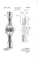
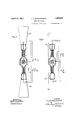
' MUL'IIUNIT TUBE Filed April 28, 1925 2 Sheets-Sheet 1 Fig. 2.
i l lllg i- R,
INVENTOR ATTORNEY April 12, 1932- E. MOUROMTSEFF Filed April 28, 1925 T m E0 r m u m m 1 ATTORNEY 'trol electrode and the cathode.
Patented Apr. 12, 1932 UNITED STATES PATENT OFFICE ILIA E. MOUROMTSEFF, OF WILKINSBURG, PENNSYLVANIA, ASSIGNOR TO WESTING- HOUSE ELECTRIC & MANUFACTURING COMPANY, A CORPORATION OF PENN- SYLVAN IA MULTIUNIT TUBE Application filed April 28, 1925. Serial No. 26.341.
My invention relates to radio sending systems, and particularly to short wave radio sending systems.
An objectof my invention is to produce a simplified short wave generating system.
Another object of my invention is to provide a duplex triode oscillator.
Another object of my invention is to provide a high-frequency generating system embodying triode oscillators in which the exciting current for the control electrode is entirely within the evacuated portion of the device.
Another object of my invention is to provide an oscillation generator in which the feed-back coil is attached directly to the control electrodes without the intervention of a seal conductor through the glass envelope.
Another object of my invention is to provide a high-power oscillator adapted to operate at high radio frequencies.
In the operation of radio-frequency oscillators, it has been customary to employ a triode vacuum tube, with a pair of inductively connected circuits, one between the anode and the cathode, and the other between the con- Such circuits are inter-related in such way as to cause the development of sustained oscillations.
This system has been found to work excellently at frequencies of the order of 1500 kilocycles or less, but, as the generated frequency is increased, the capacitance between the anode and grid becomes a greater factor in the system. Therefore, in order to obtain a sufficient grid potential an increasingly larger charging current to the electrodes is required.
By making the anode a portion of the evacuated container, the difficulties of carrying the power oscillatory current to and from the device are minimized, but such an expedient has not been found possible as a means of conveying the charging current to the grid. Instead, it has been found necessary to convey current to the grid through a wire sealed into a glass portion of the container. With a typical triode capable of handling energies of the order of 10 kilowatts at 2000 kilocycles, the charging current of the grid may reach a value of 10 or more amperes. A current value My invention provides means whereby two triodes are attached together in an intimate relation, and provisions are made for the mounting of the grid feed-back coil within the intercommunicating space. The ends of the feed-back coil are then connected to the two respective grids. By this means, the charging current for the grids need not be conveyed through a conductor sealed in the glass wall of the tube but instead flows through the interiorly disposed feed-back coil, the capacitance between the grid and anode electrodes, and a coil outside of the device and connected between the respective anodes.
By this means, the limitation imposed upon triode oscillators by the usual method of conveying the charging current to the grids thereof, is removed. Therefore, the device of my invention is adapted to the generation of oscillations at extremely high frequencies, and at very large powers.
Other objects and details of my invention will become apparent from the following description when read in connection with the accompanying drawings, wherein Figure 1 is a view in sectional elevation of an embodiment of a preferred form of my in* vention;
Fig. 2 is a diagrammatical representation of circuits and apparatus embodying the form of my invention illustrated in Fig. 1
- Fig. 3 is a diagrammatic representation of circuits and apparatus embodying my invention, and adapting it to the generation and radiation of extremely high frequency oscillation, and
Fig. 4: is a diagrammatic representation of another form of my invention, adapted for slightly lower frequencies.
Referring to Fig. 1, a pair of cylindrical metallic anodes 1 are provided having thinned edges adapted to have sealed thereto glass closures after the fashion well known in the art. One end respectively of each of the anodes 1 is closed by a glass portion 2, each of which has a re-entrant portion 3 upon which is mounted a filament assembly 4 serving as a cathode structure. Grid members 5 are mounted upon the re-entrant portions 3.
, To the opposite ends of the anodes 1 are A conductor 11 is attached to the coil 10 at any convenient point, which may be the mid point, and lead through a seal 12 to the exterior of the device. A second coil 14 may be positioned surrounding the closure 7 and is connected at its ends to the respective anodes 1." A mid-point tap 15 which is preferably quite close to the electrical center of the coil 14 is made thereto.
Referring to Fig. 2, the elements previously described are diagrammatically re resented, similar numbers representing 1' e structures. In this representation, the glass portions of the structure are omitted. The
. anodes 1 as' shown, are connected by the coil 14 having the tap 15 to its mid point. The grids 5 are connected by the coil 10, having a. tap 11 thereto. The cathodes 4 are shown as respectively connected in series, and in series with a generator 16 by means of leads 17, 18 and 19. The tap 15 to the mid point of the coil 14 is connected to the positive lead of the generator 21, the. other terminal of which is connected to the cathode lead 19. The grid lead is connected to a grid bias means 22, which may be any source of potential or may be a biasing resistance, the other terminal 0; which is connected to the cathode circuit 1 I Referring to Fig. 3, a structure similar to that of Fig. 1 is shown, and the connections, in general are similar to those of Fig. 2. In addition capacitance elements 23 and 24, are provide ,which are connected to the anodes 11. These elements serve as oscillation radiating means in the manner well known in the prior art.
Referring to Fig. 4, the capacitances 23 and 24 are replaced by an aerial 25 and a ground connection 26 which serve the same purpose at slightly lower frequencies.
In the operation of my device, energy is supplied from the generator 21 of Fig. 2 to the plate circuit, and from the generator 16 to the cathode circuit. Minor changes in current flow will result in changes in the flux in the coil 14 and in consequence, energy is elec- .tromagnetically fed from the coil 14 to the coil 10 resulting in a rise of potential at one end' of coil 10 and a fall of potential at the opposite end. The grids 5 being respectively connected to the ends of coil 10, the poten-- tial of each is caused respectively to rise and fall. I Simultaneously, the inter-electrode capacitance causes an electrostatic feed back of energy, which increases the amplitude and certainty of oscillation.
The changes in grid potential change the magnitude of the electron stream flowing between the cathodes 4 and the anodes 1 at the respective endsof the device. This change in current flow causes a re-distribution of current flow in the coil 14 and when of the proper 'sign' will cause sustained oscillations to be produced in the device in the manner similar to that of the well known oscillation generating system. 4
I In the system of my invention, the interelectrode capacitance of each set of electrodes serves as an oscillating capacitance for the serves to maintain the necessary grid bias of the grids 5 whereby the device operates upon the straight line portion of its characteristic curve. The lead 11 is, however, not required to carry'any oscillatory current but it carries only the small grid current caused by the impact of electrons upon the grid structure. Likewise, the lead 15 carries onl the directcurrent energy input which is of igh voltage and small current value.
When the device is utilized for the generation of extremely short waves with their corresponding extremely high frequencies, radiation of these oscillations may be most conveniently obtained by employing wing capacitances attached to the anodes after the manner shown in Fig. 3. By this construction, waves of very short length may be generated and radiated;
By substituting aerial and round connections 25 and 26 as shown in ig. 4, the device is adapted for the generation and radiation of the shortest commercial waves now in use, as well as longer waves when desired.
By my devices as previously described, I am enabled to obtain additional output from a single unit. If the respective sets of triode electrodes are made according to the present commercially developed designs which, at the present time are capable of translating about 10 kilowatts each, the device is adapted to the translation of double that amount of power, that is, 20 kilowatts in a device which is no more diflicult to construct than the devices of the prior art and, likewise, the device is adapted to the generation of frequencies hitherto attainable only with minute amounts of energy.
While I have shown but a single embodiment of my invention in the foregoing descriptions it is capable of various modifications therefrom without departing from the spirit thereof and it is, therefore, desired that only such limitations shall be imposed thereon as are required by the appended claims or by the prior art.
I claim as my mvent1on:
1. A space current device comprismg a pair of triodes having cathode, gr1d and anode electrodes, vapor-tlght o1n1ng means between .said triodes, whereby the same vacuum is maintained in both, and induct1ve con- I necting means between said trlodes and comprising an inductance having opposite ends connected to the respective grid electrodes and being located within said connecting means, said inductive meansfurther comprising a second inductance having opposlte ends connected to the respective anode electrodes and being located outside of said oining means and concentric with said first mentioned inductance. u 2. A space current device compr sing a container having a plurality of portions thereof of metal, and portions of a vitreous insulating material sealed thereto, sald metal portions being adapted to rece1ve an electron stream, a plurality of gr1d electrodes therem and cooperating therewith, said electrodes being supported on said vitreous portions and being adapted to control an electron stream, means electrically connecting said grids comprising a coil of conductlve materlal. positioned wholly within said contalner, and having a center tap thereto leading through sa d container, a plurality of cathodes within said metal portions and said grids, cooperating therewith and adapted to em1t electron streams.
3. A space current device comprising an evacuated container formed partly of 1nsulating material, a plurality of anodes mtegral therewith, an inductance connected thereto, coaxial therewith, and outside thereof, a
. plurality of grids therewithin, a second inductance connected therewith, positloned within said container and concentric with said first-mentioned inductance and cathode means cooperating with said anodes.
4. A space current device comprising two complete triodes, each thereof comprising a cylindrical metal anode, a vitreous closure sealed thereto and having a re-entrant portion and grid and cathode electrodes supported thereby, said cathode having current supply leads therethrough, said anodes belng joined by a vitreous coupl ng member, sald anodes, closures and coupling member comprising an impermeable conta ner adapted to be evacuated, an inductor posltloned w1thin said coupling member and connected to said grids, and a conductive lead passlng through said coupling and connected to a mid-point on said inductor, and a secondmductor surrounding said coupling, and connected to said anodes.
5. A space current device comprising a pluralit of triodes, the anodes thereof being parts 0 a common container therefor, and
an inductance surrounding said container and connected to said anodes. .1
6, A space current device comprising an osclllating circuit having two inductances and two capacitances, the capacitances being adapted to be bridged by electron streams, and an evacuated container, said capacitances and one of said inductances being within the said evacuated container.
7. A space current device comprisin an oscillating circuit having a plurality o inductances, a plurality of capacitances, an evacuated container and a plurality of electron streamsources, said capacitances'comprising anode and grid electrodes and being within said container, said electron stream sources being within said container and cooperatingwith said capacitances and an os-' cillation radiating system connectedto said oscillating circuit.
8. A space current device comprising an evacuated container and a plurality of pairs of electrodes therein, adapted'to function as capacitances in an oscillating circuit the portions of said container adjacent said electrodes being of metal adapted to cooperate as electrodes with said electrode pairs and an inductance positioned within said container and connected to certain of said electrodes.
9. A space current device comprising an evacuated container and a plurality of pairs of electrodes therein, adapted to function as capacitances in an oscillating circuit the portions of said container adjacent said electrodes being of metal adapted to cooperate as electrodes with said electrode pairs and an inductance positioned within said container and connected to certain of said electrodes and a tap connection to said inductance, insulatingly passed through said container.
10. A space current device comprising an envelope having metallic wall portions and having presses positioned at opposite ends thereof, a cathode and a grid element supported on each press, and a conductor in said no envelope interconnectin the grid elements.
11. A space current levice comprising a pair of coupled triode devices, the anodes of said triodes consisting of a pair of insulated radiating electrodes adapted to radiate substantial amounts of electromagnetic power of radio frequency.
12. A space current device comprising a pair of structurally coupled triode devices having metal shell port-ions as parts of the container and'as anodes, and a pair of oppositely extending oscillation radiating members attached thereto.
13. An electrical discharge device comprising'a cylindrical member having a cathode near each end thereof, a controlelectrode inclosed therein adjacent each cathode, means connecting said control electrodes enclosed therein, the portions of said cylindrical mem ber adjacent said cathodes being metallic and 130 conductively connected to form anodes for said cathodes, the connecting means between said control electrodes being inductively re; lated to the conductive connection between said anodes, and means for connecting external circuits to the midpoints of said control electrode interconnection and said anode structure.
14. An electrical discharge device comprising a cylindrical member having two cathodes spaced apart axially thereof, a control electrode inclosed therein adjacent each cathode, means therein connecting said control electrodes, the portions of said cylindrical member adjacent said cathodes being metallic and conductively connected to form anodes for said cathodes, the connecting means be tween said control electrodes being inductively related to the conductive connection between said anodes and means for connecting external circuits to the midpoints of said control electrode interconnection and said terconnected electrodes within said anodes to.
anode structure.
15. An electrical radiator comprising two electron emitters, a linearly extended member including conducting cylindrical surfaces enclosing said two emitters respectively, two interconnected electrodes within said cylindrical surfaces to control the electron flow between said cylindrical surfaces and said electron emitters and means for connecting external circuits to the midpoints of said control electrode interconnection and said cylindrical surfaces.
16. An electrical radiator comprising two electron emitters, a linearly extended member including conducting surfaces enclosing said two emitters respectively, two interconnected electrodes within said surfaces adapted to control the electron flow between said surfaces and said electron emitters, and inductive means between said interconnected electrodes.
17. An electrical discharge device comprising a cylindrical member having a cathode near each end thereof, a control electrode enclosed therein adjacent each cathode, means connecting said control electrodes enclosed therein, the portions of said cylindrical member adjacent said cathodes being metallic and conductively connected to form anodes for said cathodes, the connecting means between said control electrodes being inductively related to the conductive connection between said anodes and means for connecting external circuits to the mid points of said control electrode interconnection and said anode structure.
18. An electrical radiator comprising two electron emitters, a linearly extended member including conducting cylindrical anodes enclosing said two emitters respectively, two incontrol the electron flowbetwe'en said anodes and said electron emitters, and means for connecting external circuits to the midpoint of said control electrode interconnection.
19. An electrical-discharge device comprising electron-emissive cathodes spaced apart within said device, control electrodes adjacent
Priority Applications (1)
| Application Number | Priority Date | Filing Date | Title |
|---|---|---|---|
| US26341A US1853632A (en) | 1925-04-28 | 1925-04-28 | Multiunit tube |
Applications Claiming Priority (1)
| Application Number | Priority Date | Filing Date | Title |
|---|---|---|---|
| US26341A US1853632A (en) | 1925-04-28 | 1925-04-28 | Multiunit tube |
Publications (1)
| Publication Number | Publication Date |
|---|---|
| US1853632A true US1853632A (en) | 1932-04-12 |
Family
ID=21831270
Family Applications (1)
| Application Number | Title | Priority Date | Filing Date |
|---|---|---|---|
| US26341A Expired - Lifetime US1853632A (en) | 1925-04-28 | 1925-04-28 | Multiunit tube |
Country Status (1)
| Country | Link |
|---|---|
| US (1) | US1853632A (en) |
Cited By (9)
| Publication number | Priority date | Publication date | Assignee | Title |
|---|---|---|---|---|
| US2422819A (en) * | 1944-08-15 | 1947-06-24 | Eitel Mccullough Inc | External anode electron tube |
| US2423444A (en) * | 1944-01-07 | 1947-07-08 | Bell Telephone Labor Inc | Electronic discharge device for ultra high frequency energy generation |
| US2429305A (en) * | 1944-05-02 | 1947-10-21 | Marion D Barnes | Holder for test tubes |
| US2469180A (en) * | 1946-05-10 | 1949-05-03 | Amperex Electronic Corp | Self-contained high-frequency oscillator |
| US2472088A (en) * | 1943-06-18 | 1949-06-07 | Clarence A Boddie | Oscillator tube |
| US2522557A (en) * | 1943-01-25 | 1950-09-19 | Harold A Zahl | Electronic tube |
| US2707750A (en) * | 1948-06-08 | 1955-05-03 | Sylvania Electric Prod | Ultra high frequency translator |
| US3000314A (en) * | 1946-03-19 | 1961-09-19 | Edwin R Sanders | Fuze |
| US3027842A (en) * | 1946-03-04 | 1962-04-03 | John J Hopkins | Fuze |
-
1925
- 1925-04-28 US US26341A patent/US1853632A/en not_active Expired - Lifetime
Cited By (9)
| Publication number | Priority date | Publication date | Assignee | Title |
|---|---|---|---|---|
| US2522557A (en) * | 1943-01-25 | 1950-09-19 | Harold A Zahl | Electronic tube |
| US2472088A (en) * | 1943-06-18 | 1949-06-07 | Clarence A Boddie | Oscillator tube |
| US2423444A (en) * | 1944-01-07 | 1947-07-08 | Bell Telephone Labor Inc | Electronic discharge device for ultra high frequency energy generation |
| US2429305A (en) * | 1944-05-02 | 1947-10-21 | Marion D Barnes | Holder for test tubes |
| US2422819A (en) * | 1944-08-15 | 1947-06-24 | Eitel Mccullough Inc | External anode electron tube |
| US3027842A (en) * | 1946-03-04 | 1962-04-03 | John J Hopkins | Fuze |
| US3000314A (en) * | 1946-03-19 | 1961-09-19 | Edwin R Sanders | Fuze |
| US2469180A (en) * | 1946-05-10 | 1949-05-03 | Amperex Electronic Corp | Self-contained high-frequency oscillator |
| US2707750A (en) * | 1948-06-08 | 1955-05-03 | Sylvania Electric Prod | Ultra high frequency translator |
Similar Documents
| Publication | Publication Date | Title |
|---|---|---|
| US2353742A (en) | High-frequency apparatus | |
| US2412805A (en) | Ultra high frequency oscillation generator | |
| US2235414A (en) | Thermionic valve circuits | |
| US1853632A (en) | Multiunit tube | |
| US2108900A (en) | Ultrashort wave oscillation generator circuit | |
| US2308523A (en) | Electron discharge device | |
| US2423819A (en) | Vacuum tube with coupling-feedback electrode arrangement | |
| US1978021A (en) | Ultrashort wave system | |
| US2096817A (en) | High frequency oscillator | |
| US2372213A (en) | Ultra-high-frequency tube | |
| US2462137A (en) | Electron discharge device | |
| US2446017A (en) | Ultra high frequency electric discharge device and cavity resonator apparatus therefor | |
| US2404226A (en) | High-frequency discharge device | |
| US2267520A (en) | Oscillation generator system | |
| US2153131A (en) | High frequency oscillator | |
| US2051623A (en) | High frequency oscillator | |
| US2404542A (en) | Resonator for oscillators | |
| US1930499A (en) | Oscillation generator | |
| US2432193A (en) | Microwave oscillator | |
| US2051601A (en) | High frequency oscillator | |
| US2168924A (en) | Oscillator system | |
| US1997019A (en) | High frequency generator | |
| US2750455A (en) | Radio frequency controlled plasmatron | |
| US2463512A (en) | Electron discharge device | |
| US2428609A (en) | High-frequency electric discharge device |