US1853628A - Oil still condenser - Google Patents
Oil still condenser Download PDFInfo
- Publication number
- US1853628A US1853628A US177715A US17771527A US1853628A US 1853628 A US1853628 A US 1853628A US 177715 A US177715 A US 177715A US 17771527 A US17771527 A US 17771527A US 1853628 A US1853628 A US 1853628A
- Authority
- US
- United States
- Prior art keywords
- tubes
- nest
- shell
- tube
- media
- Prior art date
- Legal status (The legal status is an assumption and is not a legal conclusion. Google has not performed a legal analysis and makes no representation as to the accuracy of the status listed.)
- Expired - Lifetime
Links
Images
Classifications
-
- F—MECHANICAL ENGINEERING; LIGHTING; HEATING; WEAPONS; BLASTING
- F28—HEAT EXCHANGE IN GENERAL
- F28B—STEAM OR VAPOUR CONDENSERS
- F28B1/00—Condensers in which the steam or vapour is separate from the cooling medium by walls, e.g. surface condenser
-
- Y—GENERAL TAGGING OF NEW TECHNOLOGICAL DEVELOPMENTS; GENERAL TAGGING OF CROSS-SECTIONAL TECHNOLOGIES SPANNING OVER SEVERAL SECTIONS OF THE IPC; TECHNICAL SUBJECTS COVERED BY FORMER USPC CROSS-REFERENCE ART COLLECTIONS [XRACs] AND DIGESTS
- Y10—TECHNICAL SUBJECTS COVERED BY FORMER USPC
- Y10S—TECHNICAL SUBJECTS COVERED BY FORMER USPC CROSS-REFERENCE ART COLLECTIONS [XRACs] AND DIGESTS
- Y10S165/00—Heat exchange
- Y10S165/051—Heat exchange having expansion and contraction relieving or absorbing means
- Y10S165/052—Heat exchange having expansion and contraction relieving or absorbing means for cylindrical heat exchanger
- Y10S165/053—Flexible or movable header or header element
- Y10S165/054—Movable header, e.g. floating header
Definitions
- My invention relates to heat exchange debeing provided for preventing the egress of vices, particularly to heat exchange devices which are es ecially'adapted for use in the any oil vapor along with the condensate.
- the exprocess of-re ing crude petroleum oil and it changer comprises a shell 11 having an inlet connection 12 ad acent one end thereof, and 5! 5 has for an object to provide apparatus of the character designated which shall be capable of initially heating and subsequently vaporizing the oil in a very eflective and efiicient manner.
- my heat exchange device comprises essentially a shell portion provided with a suitable inlet and a suitable outlet for the heating medium, generally oil vapor.
- the shell is so formed that the heating agent passes completely therethrough with a minimum amount of resistance'to flow and with a minimum amount of pressure drop.
- a tube nest which is divided essentially into a heater section and a boiler or vaporizing section.
- the heater section preferably consists of a number of passes arranged in series, each pass consisting of a relatively small number of tubes while the boiler section is composed of only a single pass consisting of a relatively large number of tubes.
- Suitable means are provided for removing any oil or condensate accumulating in the shell, liquid sealing means an outlet connection 13 on the opposite side of the shell, and adjacent to the other end thereof.
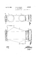
- the connection 12 is somewhat larger than the discharge connection 13, and the shell is arranged to converge from the respective connections to the opposite ends of the shell the manner shown.
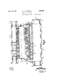
- the upper tube sheet 22 is secured to the shell in anysuitable manner, such as by means of angles 24, and, secured to this tube sheet 22, is a header 14, which is provided with an inlet connection 16, and a discharge connection 17, for circulating media.
- the header is'provided with a. number of partitions 26, for directing the circulating media through the tubes in a number of passes.
- partitions 26, are arranged so as to include substantiallythe same number of tubes in each of the first several passes through the nest, and to provide a final pass which includes a relatively large number of all of the tubes in the nest.
- The-lower tube sheet 23 is not secured to the shell, but is arranged to be movable, with respect to the shell, to allow for expansion and contraction of the tubes.
- a return header 27 Secured to this tube sheet 23, is a return header 27, which is. provided witha number of artitions 28 so disposed as to cooperate wit the partitions 26, in the upper header, in causing circulatmg media to pass through the tubes in a numher of passes in series.
- an standing wall- 29, Disposed about the periphery of the lower tube sheet 23, is an standing wall- 29, which, it will be noted, p ojects farther above the tube sheet onthe right side inFig. 3, or "adjacent the tubes in thefinal pass, than is the case on the left, where this wall is. adjacent to the tubes in the first pass.
- a wall 31 Extending downwardly between the wall29 and the nest of tubes, is a wall 31, likewise surrounding the nest of tubes, and so arranged with respectto the wall 29 as to form a liquid seal, between the interior of the shell-and a chamber 32'for collecting condensate.
- the means which provide this chamber 32 preferably, take the form. of a box-like member 41, which is adapted to be secured to the lower end of the shell in any suitable manner, as by fittin the u er flan e 43 of g PP g a form, the annular member 44 carries 'the downwardly extending wall 31, and also the upper flange 43, which latter may be secured.
- the member 41 is also provided with con- Iiections 34 and 36 which may be disposed on opposite walls of this member and are, preferably, arranged in the lower ortlon thereoff as on the walls of the box-li e portion 48.
- the connections 34 and 36 are of such a size as would be suitable for passing circulating media through the chamber 32, should it be desired to provide a nest of cooling tubes, or other cooling device, therein. In the form shown, however, these cooling tubes are not shown, as this provision is made for the purpose oftaking care of unusual conditions and, therefore, the connections 34 and 36 are closed by securing plates 39 across these connections.
- Vapor which has previously been heated is introduced, preferably through the inlet connection 12, and, due to the irregular shape of the shell, is passed through the nest of like, and consequently, all of the tubes and out through the outlet connection 13.
- This inclination of the shell wall izo serves to facilitate the longitudinal distribu tion of gaseous media to the entire length of the tube .nest dueito the fact that there is a greater temperature diiierence between the heating vapor and the circulating media in the tubes at the lowerend of the tubes of the final pass than between the heating vapor and the circulating media in the upper region of the final pass.
- This difference in heat head is suificient to draw the heating vapor directly from the vapor inlet 12 to the lower portion of the shell and in, general to effect proper longitudinal distribution of the heating vapors before they enter the nest. Once longitudinal distribution isestablished, the heating vapors, pass directly across the nest, thus rendering all of the tube surface fully effective.
- outlet connection 13 By arranging the outlet connection 13 in a similar manner, so that the wall on the outlet side of the shell 11 is inclined outwardly with respect to the tube nest in a direction to ward the outlet 13, ample provision is made for readily removing gaseous media whichhas passed through the nest and thus, for avoiding the formation of gas pockets or p other areas of poor circulation.
- tubular heat exchangers of the type described it is advantageous to have the circulating media, such as crude petroleum oil forf example, pass through the heating section of the nest inseveral passes, and this isparticularly true where heating media is available at a relatively high temperature, for in this way it is possible to'bring about an ex- I changeof heat more nearly in accordance with the contra flow principle, whereas, if the heatmg tubes are all arranged in a single pass, the heating of the circulating media is not progressive and, of course,such a heater would not involve an application of the contra flow principle and would be, comparatively 'ineficient.
- the circulating media such as crude petroleum oil forf example
- a tubular heat exchanger compnsmg a shell enclosing a vapor space and having an inlet and an, outlet, a nest of tubes traversing said space, connections for passing circulating media through the tubes in a number of passes in series, a relatively large nuIhber of the tubes of the nest being arranged in the final pass, a condensate collecting chain- I ber, and means for providing a liquidseal I around and between saidlspac'e densate collecting chamber.
- a tubular heat exchanger comprising a shell enclosing a vapor space and having an inlet and an outlet, a nest of tubes traversing said space, connections for passing circulate ing media through the tubes in a number of passes in series, a relatively large number of the tubes of the nest-being arranged in the final pass, a condensate collecting chamber, and means for providing a liquid'seal around and between said space and said condensate collecting chamber, the seal being arranged is adjacent the tubes in the first pass.
- a substantially vertical tubular heat exchanger comprising a shell enclosing a vapor space and having an inlet and an outlet, a nest of substantially vertically disposed tubes within the vapor space in said shell, tube sheets for the nest of tubes, one of the tube sheets being secured to the shell, the other of said tube sheets being movable with respect to the shell, connections for passing circulat- 7 ing media through the nest of' tubes, and meansv for providing a liquid seal between the movable tube sheet and the shell.
- a substantially vertical tubular heat exchanger comprising a shell enclosing a vapor space connections on the shell for passing gaseous media through the vapor space, a nest of substantially vertically disposed tubes within the vapor space, tube sheets for the tubes, one of said tube sheets being secured to the shell, the other of said tube .sheetslbeing movable with respect tothe shell, connections for passing circulating media through the tubesin a number of'passes in series, and means for providing a liquid seal between the movable tube sheet and the shell, the seal being arranged to overflow first from the portion thereof which is adjacent tubes in the firstpass.
- Atubular heat exchanger of the type described comprising a chamber having an inlet adjacent one end thereof, .heat transfer tubes traversing said chamber, and means for directing circulating media through said tubes in several passes in series, each of said passes except the final pass consisting of a relatively small number .of tubes and said final pass consisting of a relatively large number of tubes, said means being so constructed and arranged as to direct circulating media through said final pass in a direction toward said inlet, whereby an increasing heat head along the tubes in the final pass in a direction away from the inlet is obtained.
- a tubular heat exchanger comprising a 'shell, an inlet connection and an outlet connection on the shell for gaseous edia, a nest of tubes disposed within the shel and means for passing circulating media through the tubes in a number of passes. in series, a relatively large number 'of the tubes of the nest being arranged in the final pass, the shell and the tubes being arranged to define a vapor passage of su stantia ly uniform sectional area extending through the tube nest.
- a tubular heat exchanger comprising a shell, an inlet connection and an outlet con nection on the shell for gaseous media, a nest .of tubes disposed within the shell, and means for"-passing circulating media through the tubes in anumber of passes in series, some of the passes consisting of-like numbers of tubes and the finalpass consisting of a relatively large number of the'tubes in the nest, the shell and the tubes being arranged to define a substantially traight vapor passage of substantially uniform sectional flow-area extending through the tube nest.
- a tubular heat exchanger comprising a shell, an inlet connection and an outlet connection on the shell for gaseous media, a nest of tubes disposed within the shell, and means for passing circulating media through the tubesin a number of passes in series, a relatively large number of the tubes of the nest being arranged in the final pass, the remaining tubes of the nest being equally apportioned to the remaining passes, the shell and the tubes being arranged to direct gaseous media through the tube nest in a single pass of substantially uniform flow-area through the tnbe nest.
- the combination of a shell structure, a tube nest extendin lon itudinally through the shell structure an an inlet for gaseous media provided in a side wall of the shell structure adjacent one end thereof, said side wall being spaced away from the tube nest near the gaseous media inlet and being inclined toward the tube nest as it approaches the end of the tube nest remote from the gaseous media inlet.
- the combination of a shell structure, a tube nest extending longitudinally through the shellstructure, an inlet connection for gaseous media provided in one of the side walls of the shell structure and adjacent to one end of the tube nest, and an outlet connection for gaseous media rovided in an opposite side wall of the shed being s aced fromthe tube nest near their associat connections and being inclined toward the tube nest as they approach the opposite ends of-the shell structure.
- a casing In an air eater, a casing, tube sheets, tubes connected to one of said tube sheets, and a slidable connection between said tube sheet and casing with a yielding closure for said connection.
Landscapes
- Engineering & Computer Science (AREA)
- Mechanical Engineering (AREA)
- General Engineering & Computer Science (AREA)
- Heat-Exchange Devices With Radiators And Conduit Assemblies (AREA)
Description
April 12, 1932. D. w. R. MORGAN 8 OIL STILL CONDENSER Filed March 25, 1927 .2 Sheets-Sheet l WITNESS INVENTOR 6. "D.W.R.MorQan ATTORNEY m 193% D. W. R MORGAN OIL STILL CONDENSER Filed March 23, 192 2 Sheets-Sheet 2 INVENTOR D.w.R.M0rQan BY a. (I5 W ATTORNEY WITNESS 6.
Patented Apr. 1 i9 v ram w. n. menses, or swan'ron'a,
.nousr. ammo a a v on srrnr. cormnnsnit Application ma ma as, me.- Serial No. 177,715.
My invention relates to heat exchange debeing provided for preventing the egress of vices, particularly to heat exchange devices which are es ecially'adapted for use in the any oil vapor along with the condensate.
Referring now to the drawings, the exprocess of-re ing crude petroleum oil and it changer comprises a shell 11 having an inlet connection 12 ad acent one end thereof, and 5! 5 has for an object to provide apparatus of the character designated which shall be capable of initially heating and subsequently vaporizing the oil in a very eflective and efiicient manner.
It has for a further object to provide a heat exchange device which shall be adapted to use, as a heating medium, oil which'has been vaporized, and it has for a still further object-toprovide a heat exchange device in which the heating agent passing therethrough encounters a mlnfmum amount of resistance to flow and consequently incurs very little pressure drop. I
' These and other objects, which will be made 29 apparent throughout the further description of my invention, may be obtained by the employment of the apparatus hereinafter described and illustrated in the accompanying exchanger, the central portionthereof being.
broken away.
, Briefly speaking, my heat exchange device comprises essentially a shell portion provided with a suitable inlet and a suitable outlet for the heating medium, generally oil vapor. The shell is so formed that the heating agent passes completely therethrough with a minimum amount of resistance'to flow and with a minimum amount of pressure drop. Provided within the shell portion is a tube nest which is divided essentially into a heater section and a boiler or vaporizing section. The heater section preferably consists of a number of passes arranged in series, each pass consisting of a relatively small number of tubes while the boiler section is composed of only a single pass consisting of a relatively large number of tubes. Suitable means are provided for removing any oil or condensate accumulating in the shell, liquid sealing means an outlet connection 13 on the opposite side of the shell, and adjacent to the other end thereof. Preferably, the connection 12 is somewhat larger than the discharge connection 13, and the shell is arranged to converge from the respective connections to the opposite ends of the shell the manner shown. Dis osed within the shell, and longitudinally t ereof, is a nest of tubes 21, and suitable tube sheets 22, and '23, are provided for the nest. The upper tube sheet 22 is secured to the shell in anysuitable manner, such as by means of angles 24, and, secured to this tube sheet 22, is a header 14, which is provided with an inlet connection 16, and a discharge connection 17, for circulating media. The header is'provided with a. number of partitions 26, for directing the circulating media through the tubes in a number of passes. The
The-lower tube sheet 23 is not secured to the shell, but is arranged to be movable, with respect to the shell, to allow for expansion and contraction of the tubes. Secured to this tube sheet 23, is a return header 27, which is. provided witha number of artitions 28 so disposed as to cooperate wit the partitions 26, in the upper header, in causing circulatmg media to pass through the tubes in a numher of passes in series.
" Disposed about the periphery of the lower tube sheet 23, is an standing wall- 29, which, it will be noted, p ojects farther above the tube sheet onthe right side inFig. 3, or "adjacent the tubes in thefinal pass, than is the case on the left, where this wall is. adjacent to the tubes in the first pass. Extending downwardly between the wall29 and the nest of tubes, is a wall 31, likewise surrounding the nest of tubes, and so arranged with respectto the wall 29 as to form a liquid seal, between the interior of the shell-and a chamber 32'for collecting condensate.
The means which provide this chamber 32, preferably, take the form. of a box-like member 41, which is adapted to be secured to the lower end of the shell in any suitable manner, as by fittin the u er flan e 43 of g PP g a form, the annular member 44 carries 'the downwardly extending wall 31, and also the upper flange 43, which latter may be secured.
to the shell in the manner just described.
A discharge connection 33 shown in Figs. 1 and-2, for removing condensed vapors, and the like, from chamber 32, isprovided in the lower portion of the box-like member 48.
The member 41 is also provided with con- Iiections 34 and 36 which may be disposed on opposite walls of this member and are, preferably, arranged in the lower ortlon thereoff as on the walls of the box-li e portion 48. The connections 34 and 36 are of such a size as would be suitable for passing circulating media through the chamber 32, should it be desired to provide a nest of cooling tubes, or other cooling device, therein. In the form shown, however, these cooling tubes are not shown, as this provision is made for the purpose oftaking care of unusual conditions and, therefore, the connections 34 and 36 are closed by securing plates 39 across these connections.
Any suitable means may be provided for supporting this exchanger, but, preferably,
these means take the form of feet 37 and 38 which are provided on the opposite sides of the header 14, as shown in Figs. -1 and 2. By this arrangement, the exchanger is allowed to expand and contract as a unit, and, it Wlll readily be seen, that the construction, which permits this, is of a simple andinexpensive character.
In the operation-of the apparatus iust described, circulating media to be vaporized, as for example petroleum crude 011, 1s assed through the inlet connection 16, of header 14,"
and through the several passes of ,the nest, which are provided by the partitions 26, and
' 28, in the headers 14 and 27 respectively, and
finally; out through the final pass, which, as
shown, includes a relatively large proportion of the total-heating surface of the unit. Vapor which has previously been heated is introduced,preferably through the inlet connection 12, and, due to the irregular shape of the shell, is passed through the nest of like, and consequently, all of the tubes and out through the outlet connection 13. The arrangement of the various .ele-
instantaneous, bubbles of vapor being formed as the liquid enters the final pass increase the volume requirements and, as more and more vapor is generated with the continued apphcation of heat, the increase in volume of the circulating media becomes so great as to'considerably increase the velocity of flow through this final pass, even though it contains many more tubes than any of the previous passes.
' As a result of this gradual and progressive transformation, the vaporization of the circulating media is completed in the final pass, so that the circulating media leaves the exchanger with its volume greatly increased and at a relatively. high velocity. As the circulating media in the upper portions of the tubes of the final pass consists almost entirely of vapor at a somewhat higher temperature than the circulating media entering the final pass where the process of vaporization is at its initial stage, it will be clear that the lower portion of the tubes in this finalpass will be capable of absorbing relatively greater quanas the heating vapor, is to flow directly across a nest of tubes andnot to flow longitudinally of the nest. For this reason, it has heretofore been considered necessary to provide baffles,
or other directing means in order to secure proper longitudinal distribution so that all of the tube surface will be fully effective. These fbafiles, and the like, necessarily, produce a pressure drop and retardthe {vapor flow. and are objectionable for that reason.
In order to overcome these objectionable features, I have provided a shell of a special construction so that there will be a greater heat head available at the end cthereof remote from the vapor inlet. This'difierence in heat head is sufficient to effect proper longitudinal distribution without the aid of'baflies, or the tube surface is fully effective. l It will be clear from Figs. 1 and 2 how this difference in heat head is obtained, for it will be observed that the wall on the entrant side of the shell 11 is inclined outwardly from the tubemest in a direction toward the vapor.
inlet 12. This inclination of the shell wall izo serves to facilitate the longitudinal distribu tion of gaseous media to the entire length of the tube .nest dueito the fact that there is a greater temperature diiierence between the heating vapor and the circulating media in the tubes at the lowerend of the tubes of the final pass than between the heating vapor and the circulating media in the upper region of the final pass. This difference in heat head is suificient to draw the heating vapor directly from the vapor inlet 12 to the lower portion of the shell and in, general to effect proper longitudinal distribution of the heating vapors before they enter the nest. Once longitudinal distribution isestablished, the heating vapors, pass directly across the nest, thus rendering all of the tube surface fully effective.
By arranging the outlet connection 13 in a similar manner, so that the wall on the outlet side of the shell 11 is inclined outwardly with respect to the tube nest in a direction to ward the outlet 13, ample provision is made for readily removing gaseous media whichhas passed through the nest and thus, for avoiding the formation of gas pockets or p other areas of poor circulation.
In tubular heat exchangers of the type described, it is advantageous to have the circulating media, such as crude petroleum oil forf example, pass through the heating section of the nest inseveral passes, and this isparticularly true where heating media is available at a relatively high temperature, for in this way it is possible to'bring about an ex- I changeof heat more nearly in accordance with the contra flow principle, whereas, if the heatmg tubes are all arranged in a single pass, the heating of the circulating media is not progressive and, of course,such a heater would not involve an application of the contra flow principle and would be, comparatively 'ineficient. Considering my heat exchange apparatus from this viewpoint, it will be observed that not only is ample provision made for proper vapor distributionand for proper vapor flow, but that, by arranging'a relatively small number of tubes in each of the several passes of the heating section, it is possible to abstract a considerable portion of the heat remaining in the heating vapor after it passes the final pass, or
boiler section. As this heat transfer is effected in accordance with the contra flow. principle, it will readily be seen that a very efiicient means is also provided for heating. the circulating media up to its boiling point.
By the'arrangement of the walls 29 and I "l 3 1,-about the nest of tubes, and adjacent the movable tube sheet, a conv'nientarrangement' is provided for removing condensed vapo'rs fromthe tube nest, for, while this arrangement'doesnot in any way interfere with, thecxpansion and. contraction of the tubes,
- it will alsobenoted, that, due tothe fact ,that
i that portion of the wall 29 which is adjacent the tubes in the first pass, is the lowest, any
those tubes in the first pass, and, thus, it will be observed that the condensate is caused to flow in a direction counter to that in which the circulating media is passed through the tubes." In this way, a very eflicient means is provided for transferring heat, from the com densed vapors, to media circulating through the tubes. i
Condensed vapors, so discharged from the liquid seal, pass to the chamber 32, in which.
they are collected, and, if desired, may 'be cooled by any suitable means, as, for ex- In the event that it is desired to cool the condensed vapors which collect 1n the chamber 32, this might be accomplished by passing raw, crude oil through the connections 34 and 36, and through the cooling tubes, as cooling media for these condensed vapors, and thus effect a preliminary heating of crude oil before it is introduced into the inlet 16. While I have shown my invention in but ample, by a nest of cooling tubes (not, shown) inc one form, it will. be obvious to those skilled in the art that it is not so limited, btlt is susceptible of various changes and modificationswithout departing from the spirit thereof, and I desire, therefore, that only such "limitations shallbe placed thereupon as are imposed by the prior art or as are specifically set forth in the appended claims.
WhatIclaimis: b 1. A tubular heat exchanger comprrsmg a shell enclosing a vapor space and havmg an inlet and an outlet, a nest of tubes traversing saidspace, connections for passing circulat- I ing media through the tubes in a number of passes in series, a relatively large number of tubes of the nest being arranged in the final pass, a condensate removal connection,
and 'means for providing a liquid seal be-.
tweensaid space and said condensate removal connection. v
2. A tubular heat exchanger compnsmg a shell enclosing a vapor space and having an inlet and an, outlet, a nest of tubes traversing said space, connections for passing circulating media through the tubes in a number of passes in series, a relatively large nuIhber of the tubes of the nest being arranged in the final pass, a condensate collecting chain- I ber, and means for providing a liquidseal I around and between saidlspac'e densate collecting chamber.
, to overflow first in the portion thereof which and said con- 3. A tubular heat exchanger comprising a shell enclosing a vapor space and having an inlet and an outlet, a nest of tubes traversing said space, connections for passing circulate ing media through the tubes in a number of passes in series, a relatively large number of the tubes of the nest-being arranged in the final pass, a condensate collecting chamber, and means for providing a liquid'seal around and between said space and said condensate collecting chamber, the seal being arranged is adjacent the tubes in the first pass. 9
4;. A substantially vertical tubular heat exchanger comprising a shell enclosing a vapor space and having an inlet and an outlet, a nest of substantially vertically disposed tubes within the vapor space in said shell, tube sheets for the nest of tubes, one of the tube sheets being secured to the shell, the other of said tube sheets being movable with respect to the shell, connections for passing circulat- 7 ing media through the nest of' tubes, and meansv for providing a liquid seal between the movable tube sheet and the shell. i
5. A substantially vertical tubular heat exchanger comprising a shell enclosing a vapor space connections on the shell for passing gaseous media through the vapor space, a nest of substantially vertically disposed tubes within the vapor space, tube sheets for the tubes, one of said tube sheets being secured to the shell, the other of said tube .sheetslbeing movable with respect tothe shell, connections for passing circulating media through the tubesin a number of'passes in series, and means for providing a liquid seal between the movable tube sheet and the shell, the seal being arranged to overflow first from the portion thereof which is adjacent tubes in the firstpass. v v
6. Atubular heat exchanger of the type described comprising a chamber having an inlet adjacent one end thereof, .heat transfer tubes traversing said chamber, and means for directing circulating media through said tubes in several passes in series, each of said passes except the final pass consisting of a relatively small number .of tubes and said final pass consisting of a relatively large number of tubes, said means being so constructed and arranged as to direct circulating media through said final pass in a direction toward said inlet, whereby an increasing heat head along the tubes in the final pass in a direction away from the inlet is obtained.
7. In heat-exchange apparatus, the comv bination of a .shell' structure having an inlet and anvoutlet'for the circulation of media therethrough, a tube nest disposed within the shell structure and-includin a stationary tube sheet supporting'oneend of the tube tion of the tube nest for forming a li uid seal.
8. In heat-exchange apparatus, t e combination of a shell structure having an inlet for media to be .condensed and an outlet for the condensate derived therefrom, a nest of tubes disposed within the shell structure, an inlet connecting with one end of the tube nest 1 'for admitting heat-absorbing media thereto and an outlet connecting with the other end of the tube nest for discharging the heated media therefrom, whereby the entrant portion of the tube nest has a relatively lower temperature than the discharge portion, and means provided within the shell structure for damming up condensate about a portion of the tube nest so as to transfer'heat thereto, said dammin means being so arranged as to spill the con ensate to the condensate outlet in the vicinity of a relatively low temperature portion of the tube nest.
' 9. A tubular heat exchanger comprising a 'shell, an inlet connection and an outlet connection on the shell for gaseous edia, a nest of tubes disposed within the shel and means for passing circulating media through the tubes in a number of passes. in series, a relatively large number 'of the tubes of the nest being arranged in the final pass, the shell and the tubes being arranged to define a vapor passage of su stantia ly uniform sectional area extending through the tube nest.
10. A tubular heat exchanger comprising a shell, an inlet connection and an outlet con nection on the shell for gaseous media, a nest .of tubes disposed within the shell, and means for"-passing circulating media through the tubes in anumber of passes in series, some of the passes consisting of-like numbers of tubes and the finalpass consisting of a relatively large number of the'tubes in the nest, the shell and the tubes being arranged to define a substantially traight vapor passage of substantially uniform sectional flow-area extending through the tube nest.
11. A tubular heat exchanger comprising a shell, an inlet connection and an outlet connection on the shell for gaseous media, a nest of tubes disposed within the shell, and means for passing circulating media through the tubesin a number of passes in series, a relatively large number of the tubes of the nest being arranged in the final pass, the remaining tubes of the nest being equally apportioned to the remaining passes, the shell and the tubes being arranged to direct gaseous media through the tube nest in a single pass of substantially uniform flow-area through the tnbe nest.
12. In heat exchange apparatus, the combination of a shell structure, a tube nest extendin lon itudinally through the shell structure an an inlet for gaseous media provided in a side wall of the shell structure adjacent one end thereof, said side wall being spaced away from the tube nest near the gaseous media inlet and being inclined toward the tube nest as it approaches the end of the tube nest remote from the gaseous media inlet.
13. In heat exchange apparatus, the combination of a shell structure, a tube nest extending longitudinally through the shellstructure, an inlet connection for gaseous media provided in one of the side walls of the shell structure and adjacent to one end of the tube nest, and an outlet connection for gaseous media rovided in an opposite side wall of the shed being s aced fromthe tube nest near their associat connections and being inclined toward the tube nest as they approach the opposite ends of-the shell structure.
14. In heat exchange apparatus, the combination of a casing, a tube nest, means for supporting the tube nest in the casing and providing for movement of one end of the tube nest relative to the casing, and means.
including a liquid seal for efiecting a fluidtight joint between the casing and the movable end of the tube nest.
15. In a devicefor transferring heat from one gas to another, tubes, a casing, and means to permit relative movement between said tubes and easing, said means comprising flanges 'extendin into liquid.
16. In an air eater, a casing, tube sheets, tubes connected to one of said tube sheets, and a slidable connection between said tube sheet and casing with a yielding closure for said connection.
In testimony whereof, I have hereunto subscribed my name this eleventh day of March,
DAVID W. R. MORGAN.
1 structure and adjacent to the other end of the tube nest, said side walls
Priority Applications (1)
| Application Number | Priority Date | Filing Date | Title |
|---|---|---|---|
| US177715A US1853628A (en) | 1927-03-23 | 1927-03-23 | Oil still condenser |
Applications Claiming Priority (1)
| Application Number | Priority Date | Filing Date | Title |
|---|---|---|---|
| US177715A US1853628A (en) | 1927-03-23 | 1927-03-23 | Oil still condenser |
Publications (1)
| Publication Number | Publication Date |
|---|---|
| US1853628A true US1853628A (en) | 1932-04-12 |
Family
ID=22649695
Family Applications (1)
| Application Number | Title | Priority Date | Filing Date |
|---|---|---|---|
| US177715A Expired - Lifetime US1853628A (en) | 1927-03-23 | 1927-03-23 | Oil still condenser |
Country Status (1)
| Country | Link |
|---|---|
| US (1) | US1853628A (en) |
-
1927
- 1927-03-23 US US177715A patent/US1853628A/en not_active Expired - Lifetime
Similar Documents
| Publication | Publication Date | Title |
|---|---|---|
| US3187807A (en) | Heat exchanger | |
| US1525094A (en) | Multivane cooler | |
| US3422887A (en) | Condenser for distillation column | |
| US3182719A (en) | Multitubular heat exchanger | |
| US2946570A (en) | Vertical feedwater heater | |
| US2756028A (en) | Heat exchange apparatus | |
| US3590912A (en) | Vertical staggered surface feedwater heater | |
| US4165783A (en) | Heat exchanger for two vapor media | |
| US1790151A (en) | Heat exchanger | |
| US1918601A (en) | Heat exchanger | |
| US2848197A (en) | Condenser | |
| US1960770A (en) | Heat exchanger | |
| US1808619A (en) | Heat exchanger | |
| US1894026A (en) | Heat exchange apparatus | |
| US2174318A (en) | Unit tank heater | |
| US3363678A (en) | Multi-pressure surface condenser | |
| US1853628A (en) | Oil still condenser | |
| US3748234A (en) | Liquid distillation unit with polygonal downcomer | |
| US3348610A (en) | Heat exchangers for cooling fresh cracked gases or the like | |
| US1890185A (en) | Heat transfer device | |
| US2254070A (en) | Heat exchanger | |
| US1813234A (en) | Method and apparatus for exchanging heat | |
| US2416273A (en) | Waste heat economizer | |
| US2267695A (en) | Heat exchanger | |
| US1813057A (en) | Apparatus for heat exchanging |