US1853596A - Downdraft kiln - Google Patents
Downdraft kiln Download PDFInfo
- Publication number
- US1853596A US1853596A US471543A US47154330A US1853596A US 1853596 A US1853596 A US 1853596A US 471543 A US471543 A US 471543A US 47154330 A US47154330 A US 47154330A US 1853596 A US1853596 A US 1853596A
- Authority
- US
- United States
- Prior art keywords
- chamber
- heat
- chambers
- kiln
- flues
- Prior art date
- Legal status (The legal status is an assumption and is not a legal conclusion. Google has not performed a legal analysis and makes no representation as to the accuracy of the status listed.)
- Expired - Lifetime
Links
Images

Classifications
-
- F—MECHANICAL ENGINEERING; LIGHTING; HEATING; WEAPONS; BLASTING
- F27—FURNACES; KILNS; OVENS; RETORTS
- F27B—FURNACES, KILNS, OVENS OR RETORTS IN GENERAL; OPEN SINTERING OR LIKE APPARATUS
- F27B13/00—Furnaces with both stationary charge and progression of heating, e.g. of ring type or of the type in which a segmental kiln moves over a stationary charge
- F27B13/02—Furnaces with both stationary charge and progression of heating, e.g. of ring type or of the type in which a segmental kiln moves over a stationary charge of multiple-chamber type with permanent partitions; Combinations of furnaces
Definitions
- My invention relates to improvements in the method of burning clay products and kilns therefor, having for their primary objects the economy of fuel, the control of heat throughout the entire watersmoking and burning period and the elimination of back firing. Further objects are to provide a continuous kiln having a plurality of separatechambers in which different products can be burned, and whereby'heat from one chamber may be utilized in another and if necessary fumes from one may bedischarged directly into the stack, also to provide means whereby each of the chambers can be fired and cooled 1 independently, or fired insequence and the 270 having a plurality of chambers progressively connected by flues and being in communication with a further flue connected to a suitable stack, as will be more fully described in the'following specification andshown in the 125 accompanying drawings,'in which Fig. 1 is'a plan view of the invention taken on the line 11 of' Figure 2. I Fig. 2 is alongitudinal section taken on the line 22 of Figure 1.
- Fi g. 3 is an enlarged transverse section taken on the line 3-3 of Figure 1.
- i Fig. 4 is an enlarged half'sectional view through one of the furnaces and an interconnecting flue.
- i Fig. 5 isa longitudinal section'taken on the line 5-5 of Figure 1. f
- the numeral l indicates generally a plura'lity of chambers forming the kiln which are given reference letters A, B, C, D,"an d E respectively.
- the chambers are provlded with side walls 2 supporting an arched roof 3 and are separated from each other by partition walls 4.
- Each chamber is provided with a perforate floor 5 of any suitable type which communicates with a longitudinal flue Gtherebelow having extensions 7-leading di- 'agonally' back from each end and extending through opposite side walls 2 into a pair of intercommunicating flues 8, which in turn lead through to an opening 9 having a horizontally slidable slab 10.
- Each chamber is provided with a door opening 11 in the centre of its side walls-and a plurality of furnaces generallyindic'ated by the numeral 12 on opposite sides of each door opening 11.
- a pair of platforms 13 are formed onopposite sides of the kiln which are level with the perforate floors5 and are connected with said floors by runways 1a in which the slabs 10 are disposed.
- each passage 16 is provided with'a removable manhole cover 17 fitted level with the platform 13, and a pair of doors 18 and 19 respectively, having suitable means of operation are provided to separate the passage from its intercommunicating flue' 8 and the continuous flue 15 respectively, so that communica-- tion may be established either directly between a chamber 1 and its intercommunicating flues 8, the chamber and the continuous flues 15, or access be obtained fromthe platform 13, by removing the manhole cover 17, with any of the said flues.
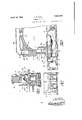
- the furnaces 12 are'fitted with "a bridge wall 20'0f suflicient height to direct the heat from the fire upwards towards the topof the chamber 1 inwhich they are formed and are each provided with fire and ash doors 21 and 22respectively, a dead plate 23 and an inclined perforate grate 24 which terminates at a substantial distance fromthe floor 25 of the furnace and thebridge wall 20 so as to define a space 26 therebetween in which'a compact body'of live coals and ash can build up, thusforming a mass capable of sustaining a substantially even temperature for relatively long periods.
- a pair of overhead heat duct s 27 Extending longitudinally above the side walls -2 is.
- each chamber'l and a plurality of transverse ducts 29 extend between. corresponding openings of each of said heat ducts, which connect through an opening 30 with the top of a chamber 1.
- lhe transverse ducts are provided with suitable dampers 31 to permit heat to flow from the ducts 27 into any desired chamber.
- the ducts 27 are in communication at both ends through pairs of vertical passages 32 with the intercommunicating flues 8A thereby serving when desired to transfer spent heat from the chamber 1A to the chamber lE.
- a dry wall 33 is erected, preferably with unburned bricks, which are burnedduring the firing of the chamber and become of com sharpal value.
- This dry wall is a temporary structure and is carried to the same height as the bridge walls 20 of thefurnaces 12.
- An arch bar 34 is placed across each door opening 11 and above it a brick closure 35 is constructed to seal the chamber.
- a removable plate 36 is placed normally to close the space between the floor of the chamber and the arch gar 34 to complete the closing of the chainer. It will be obvious that a kiln may consist of a battery of any number of chambers having flue intercommunication between adj oining chambers and also between the endmost chambers.
- the number of chambers under heat will vary according to the kind of material to be burned, but assuming commmon brick is the product dealt with one chamber would be open for withdrawal of the finished product and for the stacking of a fresh quantityof air dried bricks and four or five chambers would be under heat.
- the kiln consists of five chambers only i. e. 1A, 1B, 1C, 1D and 1E, all of which are filled, the chamber 1E would be coolingor in process of withdrawal or filling, with its several flues shut off from communication with any other chamber.
- the chamber 1D would be subjected to heat from the chamber 16 which would flow downwards from lC through its flue 60, the extension flues 7G andthe intercommunicating flues 8C up through the opening 91) behind the closure 35,, the slab 10 to said opening being outwardly withdrawn.
- the heat from the chamber 10 be properly directed, communication between the intercommunicating flues 8C and the main flues 15 is closed off by the. doors 18C or 19C.
- the material in chamber 1D during this initial heating or watersmoking process may be subjected also to heat from one or more of its furnaces 12.
- the chambers can be regulated with ease to providje'a progressive temperature increase as the burning proceeds. It will also be observed that the chambers can be fired separately or as a unit in a continuous kiln of a plura ity of chambers.
- a downdraft kiln comprising a plurality of adjoining chambers each having a loading opening, a furnace. and a smoke outlet through the floor of the chamber, a smoke flue communicating with the smoke outlet of each chamber and a smoke stack and; a pas.- sage from the intersection of each smoke out. let and the flue which communicates with; an adjoining chamber through its. loading open- In r
- a downdraft kiln comprising a.
- a downdraft kiln comprising a plurality of adjoining chambers each having a loading opening, a furnace and a smoke outlet through the floor of the chamber, a smoke flue communicating with the smoke outlet of each chamber and a smoke stack and a pas sage from the intersection of each smoke outlet and the flue which communicates with an adjoining chamber through its loading opening, a closure for the loading opening, vand means admitting air therethrough to combine with the flow from the passage to the adj oinv ing chamber.
Landscapes
- Engineering & Computer Science (AREA)
- Mechanical Engineering (AREA)
- General Engineering & Computer Science (AREA)
- Tunnel Furnaces (AREA)
Description
April 12, 1932. j W,/BA|
I IDOWNDRAFT KILN Filed July 29, 1930 2 Sheets-Sheet INVENTOR JAMES W. BALL TT'ORNEYS A ril 12, 1932. J. w. BALL DOWNDRAFT KILN Filed July 29,
1930 2 SheetsSheet 2 INVENTOR JAMES W. EA L!- ATTORNE Y5 Patented Apr. 12
PATENT OFFICE JAMES w. BALL, CLAYIBURN, BRITISH COLUMBIA, CANADA nownnanrr KILN Application filedJuly 29, 1930. Serial No. 471543.
My inventionrelates to improvements in the method of burning clay products and kilns therefor, having for their primary objects the economy of fuel, the control of heat throughout the entire watersmoking and burning period and the elimination of back firing. Further objects are to provide a continuous kiln having a plurality of separatechambers in which different products can be burned, and whereby'heat from one chamber may be utilized in another and if necessary fumes from one may bedischarged directly into the stack, also to provide means whereby each of the chambers can be fired and cooled 1 independently, or fired insequence and the 270 having a plurality of chambers progressively connected by flues and being in communication with a further flue connected to a suitable stack, as will be more fully described in the'following specification andshown in the 125 accompanying drawings,'in which Fig. 1 is'a plan view of the invention taken on the line 11 of'Figure 2. I Fig. 2 is alongitudinal section taken on the line 22 ofFigure 1.
Fi g. 3 is an enlarged transverse section taken on the line 3-3 of Figure 1. i Fig. 4 is an enlarged half'sectional view through one of the furnaces and an interconnecting flue. i Fig. 5 isa longitudinal section'taken on the line 5-5 of Figure 1. f
In the drawings like characters of referenceindicate corresponding parts in each figure.
- The numeral l indicates generally a plura'lity of chambers forming the kiln which are given reference letters A, B, C, D,"an d E respectively. The chambers are provlded with side walls 2 supporting an arched roof 3 and are separated from each other by partition walls 4. Each chamber is provided with a perforate floor 5 of any suitable type which communicates with a longitudinal flue Gtherebelow having extensions 7-leading di- 'agonally' back from each end and extending through opposite side walls 2 into a pair of intercommunicating flues 8, which in turn lead through to an opening 9 having a horizontally slidable slab 10. Each chamber is provided with a door opening 11 in the centre of its side walls-and a plurality of furnaces generallyindic'ated by the numeral 12 on opposite sides of each door opening 11. A pair of platforms 13 are formed onopposite sides of the kiln which are level with the perforate floors5 and are connected with said floors by runways 1a in which the slabs 10 are disposed. I
Extending on both sides of the kiln below the platform 13 are continuous flues 15 leading to a suitable smoke stack (not shown) and which connect with each of the flue extensions 7 through a passage 16. Each passage 16 is provided with'a removable manhole cover 17 fitted level with the platform 13, and a pair of doors 18 and 19 respectively, having suitable means of operation are provided to separate the passage from its intercommunicating flue' 8 and the continuous flue 15 respectively, so that communica-- tion may be established either directly between a chamber 1 and its intercommunicating flues 8, the chamber and the continuous flues 15, or access be obtained fromthe platform 13, by removing the manhole cover 17, with any of the said flues. I
The furnaces 12 are'fitted with "a bridge wall 20'0f suflicient height to direct the heat from the fire upwards towards the topof the chamber 1 inwhich they are formed and are each provided with fire and ash doors 21 and 22respectively, a dead plate 23 and an inclined perforate grate 24 which terminates at a substantial distance fromthe floor 25 of the furnace and thebridge wall 20 so as to define a space 26 therebetween in which'a compact body'of live coals and ash can build up, thusforming a mass capable of sustaining a substantially even temperature for relatively long periods. Extending longitudinally above the side walls -2 is. a pair of overhead heat duct s 27. which areprovided with top openings 28 adjacent the; longitudinal centre of each chamber'l and a plurality of transverse ducts 29 extend between. corresponding openings of each of said heat ducts, which connect through an opening 30 with the top of a chamber 1. lhe transverse ducts are provided with suitable dampers 31 to permit heat to flow from the ducts 27 into any desired chamber. The ducts 27 are in communication at both ends through pairs of vertical passages 32 with the intercommunicating flues 8A thereby serving when desired to transfer spent heat from the chamber 1A to the chamber lE.
Subsequent to the filling of any chamber 1 a dry wall 33 is erected, preferably with unburned bricks, which are burnedduring the firing of the chamber and become of com mercial value. This dry wall is a temporary structure and is carried to the same height as the bridge walls 20 of thefurnaces 12. An arch bar 34 is placed across each door opening 11 and above it a brick closure 35 is constructed to seal the chamber. A removable plate 36 is placed normally to close the space between the floor of the chamber and the arch gar 34 to complete the closing of the chainer. It will be obvious that a kiln may consist of a battery of any number of chambers having flue intercommunication between adj oining chambers and also between the endmost chambers. The number of chambers under heat will vary according to the kind of material to be burned, but assuming commmon brick is the product dealt with one chamber would be open for withdrawal of the finished product and for the stacking of a fresh quantityof air dried bricks and four or five chambers would be under heat. We will assume for the purpose of description that the kiln consists of five chambers only i. e. 1A, 1B, 1C, 1D and 1E, all of which are filled, the chamber 1E would be coolingor in process of withdrawal or filling, with its several flues shut off from communication with any other chamber. The chamber 1D would be subjected to heat from the chamber 16 which would flow downwards from lC through its flue 60, the extension flues 7G andthe intercommunicating flues 8C up through the opening 91) behind the closure 35,, the slab 10 to said opening being outwardly withdrawn. In order that the heat from the chamber 10 be properly directed, communication between the intercommunicating flues 8C and the main flues 15 is closed off by the. doors 18C or 19C. The material in chamber 1D during this initial heating or watersmoking process may be subjected also to heat from one or more of its furnaces 12. During the watersmoking process the moisture from the bricks is driven off as a vapour and passes down through the floor 5, the flues 6D and 7D, and the doors 18D and 191) which being open afford communication between said flues and the smoke flues 15 leading to. the stack. The. remaining doors 18 and 19 of the other chambers are left closed, so that the surplus heat from the chamber 1A will pass to the chamber 113 and the surplus heat from chamber 1B will pass to chamber 10 and so forth through the chambers included in the cycle.
Normally no firing is done in the watersmoking chamber 1D until the temperature of the bricks is materially raised by the heat from the next adjoining chamber 1C, where probably 2 to 4 furnaces are employed. In this chamber the product having been relieved of its moisture receives what is known as a preheating. In the chamber 1B a greater number of furnaces are fired to increase the temperature and carry out the oxidizing process and in chamber 1A a still greater num ber of furnaces are fired to bring the material up to a finishing heat. By this arrangement after the heat generated has been usefully employed in any chamber by passing first upwards along the side walls 2 and the roof 3 thence downwards through the bricks under treatment, it flows through to the next cham her which is under a lesser heat, so that no heat is wasted, a gradual increase of temperature is effected throughout. each chamber until the burning is completed. and by this rfnezins a very material saving is effected in Should it be desired to draw any chamber such for instance as 10, when chambers 1B and 1D are in use, heat transfer can be effect ed from chamber 1B through the roof opening 30, along a transverse duct. 29 to the overhea heat ducts 2'7 and through, another transverse duct and the openin 30 into the chamber 11). It will be obvious that since the heat genes ated in any chamber after being passed through the material to be hurned'is trans.
ferred to another chamber to. augment the heat from the furnaces of; that. chamber or to supply all the heat required for any process that extreme economy of fuel is obtained and also that through this interchange and the control of the passages through which the heat flows the temperature of the. chambers can be regulated with ease to providje'a progressive temperature increase as the burning proceeds. It will also be observed that the chambers can be fired separately or as a unit in a continuous kiln of a plura ity of chambers.
What I claim as my inventionis: I
1. A downdraft kiln comprising a plurality of adjoining chambers each having a loading opening, a furnace. and a smoke outlet through the floor of the chamber, a smoke flue communicating with the smoke outlet of each chamber and a smoke stack and; a pas.- sage from the intersection of each smoke out. let and the flue which communicates with; an adjoining chamber through its. loading open- In r A downdraft kiln comprising a. plurality of adjoining C mbers each having; aloading opening, a furnace and a smoke outlet through the floor of the chamber, a smoke flue communicating with the smoke outlet of each chamber and a smoke stack and a passage from the intersection of each smoke outlet and the flue which communicates with an adjoining chamber through its loading opening, means for closing off communication from the smoke outlet to the flue and from the smoke outlet to the adjoining chamber, said latter means being controllable from the exterior of the loading opening.
3. A downdraft kiln comprising a plurality of adjoining chambers each having a loading opening, a furnace and a smoke outlet through the floor of the chamber, a smoke flue communicating with the smoke outlet of each chamber and a smoke stack and a pas sage from the intersection of each smoke outlet and the flue which communicates with an adjoining chamber through its loading opening, a closure for the loading opening, vand means admitting air therethrough to combine with the flow from the passage to the adj oinv ing chamber.
Dated at Vancouver, B. C., this 24th day of June, 1930.
' JAMES W. BALL.
Priority Applications (1)
| Application Number | Priority Date | Filing Date | Title |
|---|---|---|---|
| US471543A US1853596A (en) | 1930-07-29 | 1930-07-29 | Downdraft kiln |
Applications Claiming Priority (1)
| Application Number | Priority Date | Filing Date | Title |
|---|---|---|---|
| US471543A US1853596A (en) | 1930-07-29 | 1930-07-29 | Downdraft kiln |
Publications (1)
| Publication Number | Publication Date |
|---|---|
| US1853596A true US1853596A (en) | 1932-04-12 |
Family
ID=23872010
Family Applications (1)
| Application Number | Title | Priority Date | Filing Date |
|---|---|---|---|
| US471543A Expired - Lifetime US1853596A (en) | 1930-07-29 | 1930-07-29 | Downdraft kiln |
Country Status (1)
| Country | Link |
|---|---|
| US (1) | US1853596A (en) |
-
1930
- 1930-07-29 US US471543A patent/US1853596A/en not_active Expired - Lifetime
Similar Documents
| Publication | Publication Date | Title |
|---|---|---|
| US1853596A (en) | Downdraft kiln | |
| US1585013A (en) | Tunnel kiln | |
| US379040A (en) | Brick-kiln | |
| US1386530A (en) | Brick-kiln construction | |
| US1471875A (en) | Tunnel kiln | |
| US1295650A (en) | Kiln. | |
| US1362158A (en) | Continuous muffle-kiln | |
| US553947A (en) | Downdraft-kiln | |
| US125832A (en) | Improvement in kilns for burning bricks, tiles | |
| US364240A (en) | Brick-kiln | |
| US1978602A (en) | Incinerator | |
| US1652570A (en) | Tunnel kiln | |
| US1732138A (en) | Furnace | |
| US566157A (en) | Brick-kiln | |
| US1226535A (en) | Ware-kiln. | |
| US644000A (en) | Continuous kiln for burning bricks or the like. | |
| US616415A (en) | Graves | |
| US685618A (en) | Kiln. | |
| US1102970A (en) | Double-stair-grate continuous kiln. | |
| US1594315A (en) | Kiln | |
| US2104781A (en) | Gas producing and smoke consuming firebox and down draft kiln | |
| US118364A (en) | Improvement in brick-kilns | |
| US1254421A (en) | Compartment-kiln. | |
| US1950375A (en) | Method of producing refractory brick and kiln therefor | |
| US1304831A (en) | And william b |