US1853593A - Instrument for exercising the fingers - Google Patents
Instrument for exercising the fingers Download PDFInfo
- Publication number
- US1853593A US1853593A US439433A US43943330A US1853593A US 1853593 A US1853593 A US 1853593A US 439433 A US439433 A US 439433A US 43943330 A US43943330 A US 43943330A US 1853593 A US1853593 A US 1853593A
- Authority
- US
- United States
- Prior art keywords
- keys
- units
- instrument
- fingers
- exercising
- Prior art date
- Legal status (The legal status is an assumption and is not a legal conclusion. Google has not performed a legal analysis and makes no representation as to the accuracy of the status listed.)
- Expired - Lifetime
Links
Images

Classifications
-
- G—PHYSICS
- G09—EDUCATION; CRYPTOGRAPHY; DISPLAY; ADVERTISING; SEALS
- G09B—EDUCATIONAL OR DEMONSTRATION APPLIANCES; APPLIANCES FOR TEACHING, OR COMMUNICATING WITH, THE BLIND, DEAF OR MUTE; MODELS; PLANETARIA; GLOBES; MAPS; DIAGRAMS
- G09B15/00—Teaching music
- G09B15/06—Devices for exercising or strengthening fingers or arms; Devices for holding fingers or arms in a proper position for playing
Definitions
- This invention has reference to instruments for exercising the fingers of the hands of players of pianoforte and other instruments played by the fingers, for the purpose as ofkeeping the muscles highly agile, or in a if) ing the keys of a pianoforte or the like.
- Qne of the primary objects and effects of the invention is to provide an instrument of the kind concerned, which while it is highly effective as regards the accomplishment of its purpose, is relatively inexpensive, simple, andlight, and one that is portable.
- the keys of the instrument are mounted at their back ends or hinges or joints on a base, and the portions in front of the joints rest on springs of a suitable strength, such as bow springs or their equivalent, which are supported on the base or carried by it, and which keep the keys in their upper nornial position; and a set of keys, say five or more white ones, with the usual accompanying black keys, are carried on the base as described, constitute a unit of the instrument.
- the units are placed and suitably held together in position, and they may be readily movable, so that a change of position may be accomplished in order that the position of the keys in relation to the hands may be varied to meet therequirements of practice.
- two units may be used, and they. will be spaced apart, one being placed and held at one end of the instrument, and the other at the other, and they will be held in thi's'relationshi'p; that is, when the units are placed in the position required, they will be held firmly together in such position.
- Any suitable d'etents or holding devices such as catches, hooks, studs orthe like may be used, and suitably fixed or mounted.
- the keys will be held as stated at the back ends by hinges of any suitable kind, whilst at the front they will be provided with a guidie device which operates in: connection with a parton the baseor thebase itself, and
- This construction of units according to this invention provides an exercising instrument which is very sensitive, light and quick in action in recovery of position, and also provides for the advantages and eifects hereinbefore specified.
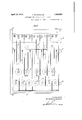
- Figure 1 is a plan of an instrument comprised of three units, held together, but readily detachable from one another; and Figure 2 is anoutside end view of the instrument.
- Figures 3 and 4 are plan and cross section, respectively, drawn to a larger scale, showing a single unit. I i
- 1 are the white keys of the instrument, and2 the black keys,
- 3 which are similar to those of an ordinary pianoforte; 3 .are the joints or hinges at the back ends of the keys, on which the keys are mounted and move; 4 are the guides at the front. part of the instrument, onwhich the keys work up and down; and 5 are the springs on which the keys rest, and by which normally they are held in their upper position.
- 6 is the base of the units, 7 the back board or wall, 8 the cover board, enclosing or covering the back parts of the keys, and 9 the front board.
- the hinges or joints 3 consist in they case shown of pins, the lower ends of which are fixed in a longitudinal bar 10 of wood or other suitable material, fixed on thebase 6.
- the keys are forked at their rear ends as shown, and the hinge pins 3 pass through holes in the lower part of the gapped end, so that it constitutes a fair free fit while the upper part of the key end above the gap, is
- the key guides 4 near the front are in the form of pins fixed in the base 6, and having round their bases washers or pads 13 of cork or similar semi-soft material, having on the upper surface a felt pad 14; and in action, the keys when depressed strike the pads 14-, and'so are cushioned and the contact rendered soft.
- the holes 15 in the keys, in which the guide pins 1 stand and work, are in slotted form, as seen in Figure 3 to allow for the circular movement of the keys about their hinges.
- the front board 9 which is attached to the base 6 encloses the space below the keys, and its upper edge extends inwards as. shown, and this part stands above the front edge of a projecting piece 16 on the underside of the ends of the keys 1, and so serves as a general stop to limit the upward movement and position of the keys 1, which keys and the keys 2, are normally pressed up by the wire springs 5, the lower ends of which are fixed in the base 6, while their upper curved ends lie and work in narrow slits, forming guides, in the lower surface of the keys.
- the black keys lie and work in gaps in the adjacent sides of the white keys 1, in the same manner as in a pianoforte; and they project up above the white keys as shown, so that the part near the cover board 8 stands about level with the top of this board.
- the back ends of the black keys 2 are of the same form and construction as those of the white keys; and the bottoms of both white and black keys are, in the construction shown, in the same horizontal plane.
- the units are each provided with rubber or soft feet 17 which will rest on the table or other surface on which they are placed.
- the meeting ends of the units are provided with devices which register or true the relative positions of the units, and this is accomplished in the case shown by the use of dowels 19 of wood, metal or the like on one edge of one unit, and corresponding holes 20 in the adjacent edge of the other unit, so that when two units are placed together, and the dowels 19 of one enter the holes 20 of the other, the true alignment of the units is produced, and the two units are engaged with one another; but they may be further secured together or locked, by catches, hooks, bolts or the like.
- hooks 21 are used, pivoted to the base 6, and the back 7, and the hooks are so adapted that when they are moved into engagement with an eye or pin 22 on the adjacent unit, they act on the eyes or pins and pull the units one towards the other and hold them together firmly.
- any other equivalent or suitable means of registering these different units in relation to one another, when placed together, and holding or locking them firmly in position together, may be used.
- one edge or face of the inter mediate unit will be provided with dowels 19, and the other with the holes 20.
- two or more units between the two end units may be used, according to requirements.
- the units may be secured together when placed together by pins which pass through the joint type of device fixed at suitable points on the case, one part of the device being on or near the edge of one unit, and the other part on or near the edge of the other unit, and through the eyes of these parts the pins are passed when connectin up the units; while when disconnecting and separating the units these pins are simply withdrawn.
- the units or instruments are light, and can be easily carried by hand; and the means for carrying the apparatus may consist of a small attache case made of any suitable material, such as papier-mach or any suitable artificial fabric, canvas or the like.
- each unit may be held in a case; and if desired a general case may be used to hold the several units, that is, the complete set of units, so that one, two or more units can be readily packed in a travelling case.
- the keys will be operated by the fingers in the usual way, and the limit of movement, when they are acted upon and pressed down is controlled by the pads 14, onto which their under surfaces come, and they are thus cushioned.
- the springs 5 are put under strain, and
- the key units may be adapted to be spaced apart, and a spacing device or dummy placed in between them and adapted to be connected together, so as to make the apparatus one in any of the manners herein described. This enables variation of position of the units to be differently placed for exercislng.
- An instrument for exercising the fingers comprising a plurality of readily connectible and disconnectible key units adapted to fit and be kept together in line, and having connected with the adjacent meeting ends a removable attachable and detachable device by which the units can be held firmly together and freed and separated at will, and the different units each having a plurality of pivoted black and white hinged keys normally pressed up by springs or elastic media.
- An instrument for exercising the fingers comprising a plurality of readily connectible and disconnectible key units, the adjacent ends of the units having parts adapted, when the ends of the units are placed together, to register same, so that in the assembled units they are all truly in line.
Description
April 12, 1932. G. WOODHOUSE 1,353,593
INSTRUMENT FOR EXERCISING THE FINGERS Filed March 27, 1930 2 Sheets-Sheet l G. WOODHOUSE 1,853,593
INSTRUMENT FOR EXERCISING THE FINGERS Filed March 27, 1950 2 Sheets-Sheet 2 April 12, 1932.
l l -llllllllulqlll -l 6. Ma /yaw:
Patented Apr. 12, 1932 UNITED STATES PATENT OFFICE GEORGE WOODHOUSE, OF LONDON, ENGLAND INSTRUMENT FOR EXERCISING THE FINGERS Application filed March 27, 1930, Serial No. 439,433, and in. Great Britain November 1, 1929.
This invention has reference to instruments for exercising the fingers of the hands of players of pianoforte and other instruments played by the fingers, for the purpose as ofkeeping the muscles highly agile, or in a if) ing the keys of a pianoforte or the like.
Qne of the primary objects and effects of the invention is to provide an instrument of the kind concerned, which while it is highly effective as regards the accomplishment of its purpose, is relatively inexpensive, simple, andlight, and one that is portable.
The keys of the instrument are mounted at their back ends or hinges or joints on a base, and the portions in front of the joints rest on springs of a suitable strength, such as bow springs or their equivalent, which are supported on the base or carried by it, and which keep the keys in their upper nornial position; and a set of keys, say five or more white ones, with the usual accompanying black keys, are carried on the base as described, constitute a unit of the instrument.
The units are placed and suitably held together in position, and they may be readily movable, so that a change of position may be accomplished in order that the position of the keys in relation to the hands may be varied to meet therequirements of practice.
As for instance, two units may be used, and they. will be spaced apart, one being placed and held at one end of the instrument, and the other at the other, and they will be held in thi's'relationshi'p; that is, when the units are placed in the position required, they will be held firmly together in such position.
Any suitable d'etents or holding devices such as catches, hooks, studs orthe like may be used, and suitably fixed or mounted.
The keyswill be held as stated at the back ends by hinges of any suitable kind, whilst at the front they will be provided with a guidie device which operates in: connection with a parton the baseor thebase itself, and
5 so that the keys are guided and kep t in their ,material.
This construction of units according to this invention, whether used in single or in multiple, provides an exercising instrument which is very sensitive, light and quick in action in recovery of position, and also provides for the advantages and eifects hereinbefore specified.
The invention, the nature of which is above described, is illustrated in the annexed drawings, in which Figure 1 is a plan of an instrument comprised of three units, held together, but readily detachable from one another; and Figure 2 is anoutside end view of the instrument. I
Figures 3 and 4 are plan and cross section, respectively, drawn to a larger scale, showing a single unit. I i
Referring to the drawings, 1 are the white keys of the instrument, and2 the black keys,
which are similar to those of an ordinary pianoforte; 3 .are the joints or hinges at the back ends of the keys, on which the keys are mounted and move; 4 are the guides at the front. part of the instrument, onwhich the keys work up and down; and 5 are the springs on which the keys rest, and by which normally they are held in their upper position. 6 is the base of the units, 7 the back board or wall, 8 the cover board, enclosing or covering the back parts of the keys, and 9 the front board.
' The hinges or joints 3 consist in they case shown of pins, the lower ends of which are fixed in a longitudinal bar 10 of wood or other suitable material, fixed on thebase 6.
The keys are forked at their rear ends as shown, and the hinge pins 3 pass through holes in the lower part of the gapped end, so that it constitutes a fair free fit while the upper part of the key end above the gap, is
provided with a longitudinal slot, so that this part can work to and fro over the hinge pin 3, whith extends up into the top or cover board 8 as shown.
Between the keys and the bed bar 10 washers or pads 10 of suitable felt or like material are introduced, and the back ends of the keys rest on these pads or cushions; while above the keys 1 and 2 and between them and the under side of the cover board 8, are similar pads 11 and 12, the hinge pin 3 passing through the pad 11, and the other pad 12 is suitably secured to the underside of the cover 8, above the keys 2, and so limits their upper movement and serves as a cushion stop.
The key guides 4 near the front are in the form of pins fixed in the base 6, and having round their bases washers or pads 13 of cork or similar semi-soft material, having on the upper surface a felt pad 14; and in action, the keys when depressed strike the pads 14-, and'so are cushioned and the contact rendered soft.
The holes 15 in the keys, in which the guide pins 1 stand and work, are in slotted form, as seen in Figure 3 to allow for the circular movement of the keys about their hinges.
The front board 9 which is attached to the base 6 encloses the space below the keys, and its upper edge extends inwards as. shown, and this part stands above the front edge of a projecting piece 16 on the underside of the ends of the keys 1, and so serves as a general stop to limit the upward movement and position of the keys 1, which keys and the keys 2, are normally pressed up by the wire springs 5, the lower ends of which are fixed in the base 6, while their upper curved ends lie and work in narrow slits, forming guides, in the lower surface of the keys.
The black keys 2.lie and work in gaps in the adjacent sides of the white keys 1, in the same manner as in a pianoforte; and they project up above the white keys as shown, so that the part near the cover board 8 stands about level with the top of this board. The back ends of the black keys 2 are of the same form and construction as those of the white keys; and the bottoms of both white and black keys are, in the construction shown, in the same horizontal plane.
The units are each provided with rubber or soft feet 17 which will rest on the table or other surface on which they are placed.
In the case shown in Figure 1, three units are employed, and theyare placed together side by side as shown so that the edges of the bases 6, and back and front boards 7, 9, and cover board 8 abut one another, and the units are in true alignment; and they are adapted to be fastened together so that they will be rigidly held together, and practically constitute a continuous single instrument. The two end units. as in the case shown, are
provided with end boards 18, which close the outer ends.
In order to have true alignment of the units when they are placed together, the meeting ends of the units are provided with devices which register or true the relative positions of the units, and this is accomplished in the case shown by the use of dowels 19 of wood, metal or the like on one edge of one unit, and corresponding holes 20 in the adjacent edge of the other unit, so that when two units are placed together, and the dowels 19 of one enter the holes 20 of the other, the true alignment of the units is produced, and the two units are engaged with one another; but they may be further secured together or locked, by catches, hooks, bolts or the like. In the case shown hooks 21 are used, pivoted to the base 6, and the back 7, and the hooks are so adapted that when they are moved into engagement with an eye or pin 22 on the adjacent unit, they act on the eyes or pins and pull the units one towards the other and hold them together firmly. But any other equivalent or suitable means of registering these different units in relation to one another, when placed together, and holding or locking them firmly in position together, may be used.
In the case shown, in which an intermediate unit or units is or are used between two end units, one edge or face of the inter mediate unit will be provided with dowels 19, and the other with the holes 20. In some cases two or more units between the two end units may be used, according to requirements.
In some cases the units may be secured together when placed together by pins which pass through the joint type of device fixed at suitable points on the case, one part of the device being on or near the edge of one unit, and the other part on or near the edge of the other unit, and through the eyes of these parts the pins are passed when connectin up the units; while when disconnecting and separating the units these pins are simply withdrawn.
The units or instruments are light, and can be easily carried by hand; and the means for carrying the apparatus may consist of a small attache case made of any suitable material, such as papier-mach or any suitable artificial fabric, canvas or the like. In some cases each unit may be held in a case; and if desired a general case may be used to hold the several units, that is, the complete set of units, so that one, two or more units can be readily packed in a travelling case.
In using the apparatus the keys will be operated by the fingers in the usual way, and the limit of movement, when they are acted upon and pressed down is controlled by the pads 14, onto which their under surfaces come, and they are thus cushioned. In the action the springs 5 are put under strain, and
upon the pressure of the fingers being removed, the springs react, and move the keys upwards about their hinges 3 quickly, so that the action of the keys is very sensitive and rapid, and a high rate of action or striking of the keys by the fingers is possible. In the return action of the keys their end projections 16 will strike the pad 23 on the overhanging edge of the front board 9.
In some cases the key units may be adapted to be spaced apart, and a spacing device or dummy placed in between them and adapted to be connected together, so as to make the apparatus one in any of the manners herein described. This enables variation of position of the units to be differently placed for exercislng.
What is claimed is 1. An instrument for exercising the fingers comprising a plurality of readily connectible and disconnectible key units adapted to fit and be kept together in line, and having connected with the adjacent meeting ends a removable attachable and detachable device by which the units can be held firmly together and freed and separated at will, and the different units each having a plurality of pivoted black and white hinged keys normally pressed up by springs or elastic media.
2. An instrument for exercising the fingers comprising a plurality of readily connectible and disconnectible key units, the adjacent ends of the units having parts adapted, when the ends of the units are placed together, to register same, so that in the assembled units they are all truly in line.
3. An instrument for exercising the fingers as defined in claim 2, wherein the adjacent edges of the casing in which the fingers lie and are fixed are provided alternatively with dowels and corresponding apertures which fit in one another and register the position of the respective units, and also with catch fasteners adapted to hold the sections together at the meeting faces.
4. An instrument for exercising the fingers as defined in claim 2, and wherein the keys are disposed within an open case provided with an overhanging upper partial lid at the back, and a pivot pin extending through the back ends of the keys and carried in the overhanging part and the base of the case.
In testimony whereof I have signed my name to this specification.
GEORGE WOODHOUSE.
Applications Claiming Priority (1)
| Application Number | Priority Date | Filing Date | Title |
|---|---|---|---|
| GB1853593X | 1929-11-01 |
Publications (1)
| Publication Number | Publication Date |
|---|---|
| US1853593A true US1853593A (en) | 1932-04-12 |
Family
ID=10892016
Family Applications (1)
| Application Number | Title | Priority Date | Filing Date |
|---|---|---|---|
| US439433A Expired - Lifetime US1853593A (en) | 1929-11-01 | 1930-03-27 | Instrument for exercising the fingers |
Country Status (1)
| Country | Link |
|---|---|
| US (1) | US1853593A (en) |
-
1930
- 1930-03-27 US US439433A patent/US1853593A/en not_active Expired - Lifetime
Similar Documents
| Publication | Publication Date | Title |
|---|---|---|
| US2720396A (en) | Exercising apparatus | |
| US1548849A (en) | Exercising apparatus | |
| US3113480A (en) | Practice drum pad | |
| US1853593A (en) | Instrument for exercising the fingers | |
| US1531670A (en) | Foot-exercising device | |
| US2072511A (en) | Piano teaching apparatus | |
| US3981221A (en) | Portable keyboard | |
| US4154135A (en) | Musical instrument | |
| US638632A (en) | Musician's finger-strengthener. | |
| GB290159A (en) | A new or improved portable desk and rest for use in railway coaches | |
| US2517896A (en) | Stand attachment for musical instruments | |
| US886591A (en) | Finger-spreading apparatus. | |
| Dennis | A block elevated maze for rats. | |
| US1854059A (en) | Exercising device | |
| US674604A (en) | Musical instrument. | |
| US231323A (en) | Mechanical musical instrument | |
| US1853728A (en) | Music table | |
| US173205A (en) | Improvement in hand-guides for pianos | |
| US2701497A (en) | Keyboard positioning control | |
| US2900862A (en) | Pedal extensions for organs | |
| US2128293A (en) | Auxiliary music rack for pianos | |
| US1665563A (en) | Foldable pocket piano keyboard | |
| US649174A (en) | Piano. | |
| US641800A (en) | Auxiliary pedal for musical instruments furnished with pedals. | |
| US2467086A (en) | Stringed musical instrument |