US1853591A - Crinkling machine - Google Patents
Crinkling machine Download PDFInfo
- Publication number
- US1853591A US1853591A US288342A US28834228A US1853591A US 1853591 A US1853591 A US 1853591A US 288342 A US288342 A US 288342A US 28834228 A US28834228 A US 28834228A US 1853591 A US1853591 A US 1853591A
- Authority
- US
- United States
- Prior art keywords
- cylinder
- crinkling
- roll
- machine
- doctor
- Prior art date
- Legal status (The legal status is an assumption and is not a legal conclusion. Google has not performed a legal analysis and makes no representation as to the accuracy of the status listed.)
- Expired - Lifetime
Links
- 238000010276 construction Methods 0.000 description 4
- 239000004744 fabric Substances 0.000 description 3
- PVNIIMVLHYAWGP-UHFFFAOYSA-N Niacin Chemical compound OC(=O)C1=CC=CN=C1 PVNIIMVLHYAWGP-UHFFFAOYSA-N 0.000 description 1
- 238000013459 approach Methods 0.000 description 1
- 230000003247 decreasing effect Effects 0.000 description 1
- 238000012986 modification Methods 0.000 description 1
- 230000004048 modification Effects 0.000 description 1
- 238000005192 partition Methods 0.000 description 1
- 230000002093 peripheral effect Effects 0.000 description 1
Images

Classifications
-
- B—PERFORMING OPERATIONS; TRANSPORTING
- B31—MAKING ARTICLES OF PAPER, CARDBOARD OR MATERIAL WORKED IN A MANNER ANALOGOUS TO PAPER; WORKING PAPER, CARDBOARD OR MATERIAL WORKED IN A MANNER ANALOGOUS TO PAPER
- B31F—MECHANICAL WORKING OR DEFORMATION OF PAPER, CARDBOARD OR MATERIAL WORKED IN A MANNER ANALOGOUS TO PAPER
- B31F1/00—Mechanical deformation without removing material, e.g. in combination with laminating
- B31F1/12—Crêping
Definitions
- FRANK e. wrxsrnom, or BROOKLYN, iv Ew Yonx, AssIGNonro BARTLETT ARKELL, or p NEW YORK, 1 .2.
- My invention relates to machines for gree of uniformity, fineness and stretchabili ty, which is capable of operation at high speed, and which may be easily adjusted' to meet different conditions. Still further ob jects of the invention are to provide a novel and improved crinkling cylinder and doctor for crinkling machines.
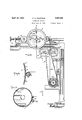
- Figure 1 is a plan viewof a portion of a" machine embodying the features of the invention in their preferred form;
- Fig. 2 is a sectional view taken on the line 22 of Fig. 1; V
- Fig. 3 is a detail transverse sectionalview of a portion of the crinkling cylinder, and doctor of the machine;
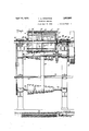
- Fig. f is a transverse sectional view taken on the line H of Fig. 2; h
- Fig. 5 is a detail side view of a portion of the doctor; and j v Fig. 6 is a transverse sectional view, partly diagrammatical, through the crinkling cylinder and doctor roll of the machineand showing the paper strip presented to the crinkling cylinder in a different manner than is shown in Figs. 1 and 2.
- the paper 2 to be crinkled is passed beneath a guide roll 4, over the upper half of a crinkling cylinder6, and is then stripped from the cylinder by means of a doctor 8 which delivers the crinkled paper to a suitablebelt conveyor 10 for conveying. b it from the machine; I l,
- the crinkling cylinder is of hollow construction its periphv eral surface is provided with perforations 12, and means is provided for exhausting air fromthe interior of the cylinder.
- the per? forations are preferably arranged in uniformly staggered relation as shown, sothat the paper; will resist the stripping action of l V the doctor at closely spaced diagonally or 1 zigzag varying points throughout the width of the paperr 1
- the doctor 8 is in the form of a roll of small diameter-with relation to the crinkling cylinder, the doctor in the machine at present constructed being three quarters of an inch in diameter while the crinkling cylinder is nine inches in diameter.
- the doctor roll is. grooved, or fluted, to provide a plurality of equally spaced radially projectinglribs 114,
- the doctor roll is arranged in substantial contact with the crinkling cylinder and is driven in the same direction as and at a less surface speed than the cylinder.
- the proper relative speeds of the cylinder and roll depend on thequality or thiclmess ofthe paper and the finenessand stretchability of the crinkling desired. Accordingly, means is provided in the illustrated machine for varying the relative surface speeds of the. cylinder and :doctor roll as desiredv to meet different conditions. ,i r
- the paper approaches the bite ofthe crinklingj cylinder and roll the .ribscontinuously and uniformly act on the paper at a plurality of I spirally. changing points throughout the width of the paper to strip 'thepaper from the.
- The-prinlding cylinder is' driven by a gear 34 formedon one end wa1l16whichis operatively'engaged by'a" gear 38'seeured on the main-shaft" 40026 the machine; which shaft maybe driven-*byabeltand pulley42;
- a pipe- 46 extends; axially through the crinklingcylinder with its ends secured in apertures 'in the endwalls' 16; one end thereofbeing: in
- wan-ans means are provided for in creasing'or decreasing the width of the perforated suction surface of the crinkling cylinder to accommodate different widths of paper to be operated upon, so as to ensure the paper completely covering all of the perfoyl rated upper portion ofthe crinkling cylinder incommunication with the air exhausting means; thus-"insuring the paperuniformlyad heringto the crinkling cylinder throughout its'widtlrs V
- the doctor roll 8' has-reduced ends thatare j ournaled in the ends of rearwardly "project'- ing bracket ari'n-s 56 on a cross ba r 58 secured onflthe machine fra'me;the cross-bar being'adj ustab-ly secured on the frame to permit the doctor roll to-be accurately adjustedwith relation to the 'crinkling cylinder.
- the driving connection between the doctor roll and the main shaft 450,"- comprises a sprocket'chain 60 which passes over sprocket wheels respectively secured” onone of the re;
- What I claim is a In a machine for crinklin paper and other fabric, a crinkling cylin er of hollow construction having its peripheral wall provided with perforations arranged in substantially staggered relation, means for creating a partial vacuum in the cylinder to cause the fabric to be held to the surface of the cylinder, and a doctor for stripping the fabric from the cylinder comprising a roll having radially projecting ribs arranged spirally longitudinally thereof.
Landscapes
- Engineering & Computer Science (AREA)
- Mechanical Engineering (AREA)
- Paper (AREA)
Description
April 12, 1932.
F. G. WIKSTROM CRINKLING MACHINE s Sheets-Sheet Filed June 26, 1928 v a. 5. f5
INVENTOR FRQ NK C-.W|KSTROM ATTORNE April 1932- F. G. WIKSTROM 1,853,591
- CRINKLING MACHINE FiledJune 26, 1928 3 Sheets-Sheet 2 [NVENTOR FRANK G. WIKSTROM ATTORNEY-I April 12,1932. F. G. WIKSTROM ,8 9
CRINKLING MACHINE Filed June 26, 1928 is Sheets-Sheet 3 TOR V RANK 6' WIKSTROM VEN Patented Apr. 12, I932 UNIE era's-Es PATENT OFFICE; I Y
FRANK e. wrxsrnom, or BROOKLYN, iv Ew Yonx, AssIGNonro BARTLETT ARKELL, or p NEW YORK, 1 .2.
cnnvxmne MACHINE.
rApplication filed June 26, 1928. Serial No. 288,342.
My invention relates to machines for gree of uniformity, fineness and stretchabili ty, which is capable of operation at high speed, and which may be easily adjusted' to meet different conditions. Still further ob jects of the invention are to provide a novel and improved crinkling cylinder and doctor for crinkling machines.
The several features of the invention, whereby the above-mentioned andother obj ects may be attained, will be clearly understood from the following description and accompanying drawings, in which:
Figure 1 is a plan viewof a portion of a" machine embodying the features of the invention in their preferred form;
Fig. 2 is a sectional view taken on the line 22 of Fig. 1; V
Fig. 3 is a detail transverse sectionalview of a portion of the crinkling cylinder, and doctor of the machine;
Fig. f is a transverse sectional view taken on the line H of Fig. 2; h
Fig. 5 isa detail side view of a portion of the doctor; and j v Fig. 6 is a transverse sectional view, partly diagrammatical, through the crinkling cylinder and doctor roll of the machineand showing the paper strip presented to the crinkling cylinder in a different manner than is shown in Figs. 1 and 2.
In myv improved machine as illustrated in the drawings, the paper 2 to be crinkled is passed beneath a guide roll 4, over the upper half of a crinkling cylinder6, and is then stripped from the cylinder by means of a doctor 8 which delivers the crinkled paper to a suitablebelt conveyor 10 for conveying. b it from the machine; I l,
In the illustrated machine the necessary adherence of the paper to the crinkling cyl-.
inder 6is accomplished by atmospheric pressure. To provide for this, the crinkling cylinder is of hollow construction its periphv eral surface is provided with perforations 12, and means is provided for exhausting air fromthe interior of the cylinder. 'The per? forations are preferably arranged in uniformly staggered relation as shown, sothat the paper; will resist the stripping action of l V the doctor at closely spaced diagonally or 1 zigzag varying points throughout the width of the paperr 1 The doctor 8 is in the form of a roll of small diameter-with relation to the crinkling cylinder, the doctor in the machine at present constructed being three quarters of an inch in diameter while the crinkling cylinder is nine inches in diameter. The doctor roll is. grooved, or fluted, to provide a plurality of equally spaced radially projectinglribs 114,
which extend spirally longitudinally of the roll. The doctor roll is arranged in substantial contact with the crinkling cylinder and is driven in the same direction as and at a less surface speed than the cylinder. The proper relative speeds of the cylinder and roll depend on thequality or thiclmess ofthe paper and the finenessand stretchability of the crinkling desired. Accordingly, means is provided in the illustrated machine for varying the relative surface speeds of the. cylinder and :doctor roll as desiredv to meet different conditions. ,i r
VViththis construction it will be apparent that due to the spiral form of the projecting ribs of the relatively small doctor roll, asf
the paper approaches the bite ofthe crinklingj cylinder and roll the .ribscontinuously and uniformly act on the paper at a plurality of I spirally. changing points throughout the width of the paper to strip 'thepaper from the.
the completed product.
to the nature of the crinkling action of;
in. The ends of this shell are closed by'iwans" 16 which are held in place by bolts-or rods 18, and are respectively secured by bolts 22 to axially arranged tubular trunnions 24 and 26. The trunnion 24 is tubular and is j0urnaled in a "stir-flingbox 28 mounted in one of The inner 'end'of thlstr-i'lnnion is 1n" communication Wlth the the niac'hiii'e side frames.
interior of the c'rinkling' cylinder, and its outer end is in a1inement with a pipe safer connection with a 'suitable suction fan or other suetion mean's for exhausting air from the ifiterior of the crinkl-in'g cylinder) The" righthand trunnion 26 is journaled inasuitablebearing in the machine frame and isheld from axial'movem'entso as to hold the crinkling cylinder from axial movement'by means of collars 32 secured thereon.
The-prinlding cylinder is' driven by a gear 34 formedon one end wa1l16whichis operatively'engaged by'a" gear 38'seeured on the main-shaft" 40026 the machine; which shaft maybe driven-*byabeltand pulley42; I
order to accommodate the crinkling cylinder for different widths of paper, the r interionthereofisdividedinto a plurality of shell is made in separateisections" 56 which compartments by' means of transverse parti tions 7 44*, and means is provided for shutting ofi -o'n'e or'inor'e of the' 'compartments from the air exhaustingmea ns' so thatonly those compartments overwhich the paper passes 'will bei in=communicationwith theair ex-' haifsting means. Toprovide'for this, a pipe- 46 extends; axially through the crinklingcylinder with its ends secured in apertures 'in the endwalls' 16; one end thereofbeing: in
communication with the" exhaust pipe 30' through the'i associated tubular trunnion 24';- The pipe/ 11:6 provided 'with apertures 48 leading into each of the compartmentsin the crinkling cylinder. The right-hand trunnion 26*is horedioutto receive an airtight piston 50 whichi's provided with an operating stem or rod'bQ'r'extending through a-stufling'box' 54" in the trunnion. Withthis'construction; by shiftingthe piston 50 longitudinally, one or more of the compartments" in the V crinkling cyliiider maybe shut-off from the aiiiexhaust pip -30? I In somefca'ses, however,' in orderito 'a'ccomf modatfe different" widths ofpaperrit maybe found desirable; to lengthen or' shorten v the crinklin bylinder; To this nd; the {cylinder .are arrangedefidtofend, andare'all'detachably held together by means of the bolts 18 so that the sections may be easily taken apart and a less number used or others substituted.
Also, it is sometimes desirable to substitute another cylinder of different diameter or havingaperforated surface of a diife'rentlength. This; of" course, may be easily accomplished upon, removing the bolts 24 so as to detach .the cylinder from its trunnions 24 and 26.
1 Thus wan-ans means are provided for in creasing'or decreasing the width of the perforated suction surface of the crinkling cylinder to accommodate different widths of paper to be operated upon, so as to ensure the paper completely covering all of the perfoyl rated upper portion ofthe crinkling cylinder incommunication with the air exhausting means; thus-"insuring the paperuniformlyad heringto the crinkling cylinder throughout its'widtlrs V The doctor roll 8' has-reduced ends thatare j ournaled in the ends of rearwardly "project'- ing bracket ari'n-s 56 on a cross ba r 58 secured onflthe machine fra'me;the cross-bar being'adj ustab-ly secured on the frame to permit the doctor roll to-be accurately adjustedwith relation to the 'crinkling cylinder.
The driving connection between the doctor roll and the main shaft 450,"- comprises a sprocket'chain 60 which passes over sprocket wheels respectively secured" onone of the re;
duced ends .of the'doctor roll'and a counter shaft 62' mounted-in bearings-in-the lower part of the machineframe- Thiscoun ter shaft is driven by a belt' 64' which passes over a conepulley 'thereon and an oppositely arranged cone pulley-011 a shaft 66 which is" driven'by a gear 68 Y thereon that engages" a gear 38 onthe main shaft 40.- Abelt' shifting rod 7 0 is provided'for shifting thebelt on the cone pulleys 'to vary thespeed of the" doctor 7 roll with relation t'o' th'e speed of the crifnklingcylinderasidesired;
;;T1 l belt conveyor 10 "is driven by when 72which passes over mpulleyon' the shaft 71L of the conveyor, and a Pulley orithecounter The guide roll tis secured'o'n'ar shaft? which has it's ends j'ournaled'in blocks The blocks are pressed forwardly by adjust'ahly';
mounted to slideontlie machine frame.
mounted coiled springs-80 to cause the guide .roll to tightly press the paper against the crinkling-roll.
The perforations in the under portion of the crinkling cylindermay beclosed from the suction device by any suitable means so as to V prevent-leakageof air through them If desired, this result may beia'cc'omplished by first passing the paper over a; guide 'roll 80,
(Fig. 6) spaced-a distance-below thedoctor r011 andjin close proximity to the crinklin cylinder and then mak over? the' crinkl-ing' cylinder to the 'doctorrollin Theperforation's between the guide roll 80 and the doctor roll may be closed by a suitable cover 82.
As will be evident to those skilled in the art my invention permits various modifications without departing from the spirit thereof or the scope of the appended claim.
What I claim is a In a machine for crinklin paper and other fabric, a crinkling cylin er of hollow construction having its peripheral wall provided with perforations arranged in substantially staggered relation, means for creating a partial vacuum in the cylinder to cause the fabric to be held to the surface of the cylinder, and a doctor for stripping the fabric from the cylinder comprising a roll having radially projecting ribs arranged spirally longitudinally thereof.
In testimony whereof, I have signed my name to this specification this 19th day of d June, 1928. FRANK G; WIKSTROM,
Priority Applications (1)
| Application Number | Priority Date | Filing Date | Title |
|---|---|---|---|
| US288342A US1853591A (en) | 1928-06-26 | 1928-06-26 | Crinkling machine |
Applications Claiming Priority (1)
| Application Number | Priority Date | Filing Date | Title |
|---|---|---|---|
| US288342A US1853591A (en) | 1928-06-26 | 1928-06-26 | Crinkling machine |
Publications (1)
| Publication Number | Publication Date |
|---|---|
| US1853591A true US1853591A (en) | 1932-04-12 |
Family
ID=23106691
Family Applications (1)
| Application Number | Title | Priority Date | Filing Date |
|---|---|---|---|
| US288342A Expired - Lifetime US1853591A (en) | 1928-06-26 | 1928-06-26 | Crinkling machine |
Country Status (1)
| Country | Link |
|---|---|
| US (1) | US1853591A (en) |
-
1928
- 1928-06-26 US US288342A patent/US1853591A/en not_active Expired - Lifetime
Similar Documents
| Publication | Publication Date | Title |
|---|---|---|
| US1437843A (en) | Machine for feeding corrugated board | |
| US1550084A (en) | Paper-crinkling machine | |
| US843781A (en) | Apparatus for cutting, folding, and interfolding sheets or units. | |
| US1853591A (en) | Crinkling machine | |
| US1170209A (en) | Paper-lubricating device for printing-presses. | |
| GB273610A (en) | Improvements in the dryer part of paper making machines | |
| US1548790A (en) | Paper crinkling | |
| US3061505A (en) | Method and apparatus for imparting enhanced stretchability to paper | |
| US724609A (en) | Cracker or biscuit machine. | |
| US1692720A (en) | Web-converting apparatus | |
| US3515780A (en) | Process for drying gel-regenerated cellulose film | |
| US1702166A (en) | Paper-crinkling machine | |
| US1548789A (en) | Paper-crinkling machine | |
| US2100522A (en) | Manufacture of printed paper articles | |
| US720593A (en) | Apparatus for producing perforated sheets of wood-pulp. | |
| US1315924A (en) | Production of heavy paper | |
| US1582839A (en) | Paper-crinkling machine | |
| US1196888A (en) | Process of softening paper. | |
| US1680797A (en) | Paper-crinkling apparatus | |
| US1283888A (en) | Automatic paper-machine. | |
| US860696A (en) | Apparatus for softening paper. | |
| US1606554A (en) | Construction of envelope flap gumming and drying machines | |
| US2896710A (en) | Suction couch roll device | |
| US2990013A (en) | Paper making machines | |
| US1519696A (en) | Paper machine |