US1853561A - Mechanical pencil - Google Patents
Mechanical pencil Download PDFInfo
- Publication number
- US1853561A US1853561A US756635A US75663524A US1853561A US 1853561 A US1853561 A US 1853561A US 756635 A US756635 A US 756635A US 75663524 A US75663524 A US 75663524A US 1853561 A US1853561 A US 1853561A
- Authority
- US
- United States
- Prior art keywords
- lead
- holder
- tube
- pencil
- ferrule
- Prior art date
- Legal status (The legal status is an assumption and is not a legal conclusion. Google has not performed a legal analysis and makes no representation as to the accuracy of the status listed.)
- Expired - Lifetime
Links
Images

Classifications
-
- B—PERFORMING OPERATIONS; TRANSPORTING
- B43—WRITING OR DRAWING IMPLEMENTS; BUREAU ACCESSORIES
- B43K—IMPLEMENTS FOR WRITING OR DRAWING
- B43K21/00—Propelling pencils
- B43K21/02—Writing-core feeding mechanisms
- B43K21/08—Writing-core feeding mechanisms with the writing-cores fed by screws
-
- Y—GENERAL TAGGING OF NEW TECHNOLOGICAL DEVELOPMENTS; GENERAL TAGGING OF CROSS-SECTIONAL TECHNOLOGIES SPANNING OVER SEVERAL SECTIONS OF THE IPC; TECHNICAL SUBJECTS COVERED BY FORMER USPC CROSS-REFERENCE ART COLLECTIONS [XRACs] AND DIGESTS
- Y10—TECHNICAL SUBJECTS COVERED BY FORMER USPC
- Y10T—TECHNICAL SUBJECTS COVERED BY FORMER US CLASSIFICATION
- Y10T29/00—Metal working
- Y10T29/49—Method of mechanical manufacture
- Y10T29/49826—Assembling or joining
- Y10T29/49908—Joining by deforming
- Y10T29/49925—Inward deformation of aperture or hollow body wall
- Y10T29/49927—Hollow body is axially joined cup or tube
- Y10T29/49929—Joined to rod
Definitions
- This invention relates to mechanical pencils and their method of manufacture.
- the present invention has reference to a pencil in which a spllt tube serves as a lead holder, the lead holder containing a leadv follower which is moved relatively to the pencil on rotation of the tube and by exerting a pressure on the leads, causing one of them to project from the pencil ti p
- the object of the invention is to provide a mechanical pencil which will effectively perform its intended purpose and which may be economically produced. This end is achieved in the pencil illustrated in the drawings which admirably lends itself to economical production because of the arrangement and character of the parts.
- composition casings are dilieult and costly to manufacture and do not simulate the ordinary non-mechanical ncil either in appearance or feel to a cient degree to easily make the habitual wood pencil user a convert tothe mechanical encil.
- the resent invention affords a mec anical pencll which looks and feels similar to the ordinary pencil and which may be produced at a cost not much exceeding the cost of the non-mechanical wood pencil. This end is partly achieved by utilizing a wood shell or casing consisting of two or more complementary shell parts which are united to each other along vertical edges on opposite sides of an element of a lead propelling mechanism.
- Another phase of the invention resides in the provision of a tip which nishes oif the end of the pencil and serves as a clutch to frictionally engage and support the writing end of the lead.
- a still further phase ofthe invention ref sides in the provision of an eraser ferrule which serves as a manually operable member to actuate the feed mechanism and is guided by a portion vof it.
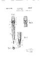
- Fig. 1 is a vertical section of the pencil partly fragmentary.
- Fig. 2 is a sectlon of Fig. 1 on the line 2 2.
- Fig. 3 is a fragmentary vertical section of Fig. 1, the section being taken at right angles to the section shown in Fig. l.
- Fig. 4 is a section of Fig. 3 on the line 4 4.
- Fig. 5 is a section of Fig. 1 on the line 5 5.
- Fig. 6 is a similar view to that shown in Fig. 5 with the lead removed and the parts in their normal position.
- 7 7 F7ig. 7 is a section of Fig. 5 on the line Fig. 8 shows the manner of assembling some of the parts.
- Fig. 9 is a fragmentary elevation partly so 1n section.
- Fig. 10 is an enlarged detail view of the tip partly in section of a modification of the invention.
- Fig. 11 is a section of Fig. 9 on the line u 11-11, and
- Fig. 12 is a fragmentary view of another modification of the connection between the ferrule.
- a shell or casing A preferably comprises a plurality of continuous shell strips A united along their vertical edges and enclosing the major portion of a lead feeding mechanism element. While the shell A in the preferred embodiment consists of a plurality of strips as indicated, the invention is not necessarily limited to the use of a plurality of shell parts since a unitary shell might be used as will be readily understood.
- a feed tube B having a thread B formed therein is located within the shell bore and is preferably held solel by frictional enga ement with the shell, alt ough of course an a hesive might be also used between the shell and the feed tube B.
- the writing end of the tube B is tapered to form a guide tip B", and is carried beyond the shell so as to give a iinished appearance to the pencil and to afford a means to effectively 1de and support the lead which is designe to project through its apertured end.
- a lead holder C adapted to be inserted in the threaded tube B has one end spun over an inner upstanding annular rim D ofa cu .D as shown in Fig. 1, thereby securely locEin the cup to the holder.
- the outer rim D ogf the cup D extends upwardly and flares outwardly and has an annular peripheral deression as shown to lock with a correspondingly shaped portion of an eraser ferrule E which in turn carries the eraser F in the usual manner.
- the ferrule, cup and holder are securely locked together so that the ferrule E may serve as a manually operable member to rotate the feed holder.
- cup D is shown as having upstanding rims nevertheless they might also be dependent, the cup in this case being forced over the inside of the dependent cup rim as will be readily understood
- the writing end of the holder or split tube C of the encil is split to form thejtripartite clutch in the ⁇ man ner shown more particularly in Figs. l, 5, 6 and 7, the split clutch parts due to their resiliency aifordin a substantial frictional enga ement with t e lead to firmly yet resilient y support the lead in conjunction with the apertured end of the tube B, particularly during the writin o eration.
- This clutch C has an annular gead) C on its internal periphe which is in actual contact with the lead, lthereby affording a slightly widened mouth G to facilitate the insertlon of thel leads into the holder C, which is loaded by pushin the requisite number of leads throng its end B and the clutch C. It will be observed from an inspection of Figs. 5 and 6 that when the segmentsof the clutch are expanded by the insertion of alead, the sharp vertical edges of the segment bite the lead (due to the fact that the radius of the arc of the segment is less than that of the lead) and effectively prevent any rotation of the lead relatively to t e pencil.
- the lead holder C also has a vertical ide slot H and contains a follower J which 1s ar ranged to bear against the rearmost lead contained in the holder to feed the series of leads toward the ti
- This follower may be and referably is ormed from a wire strip having a flattened bent sinuous portion to form the wings K which engage the threads B of the feed tube B.
- the rotation of the eraser ferrule E and its attached tube or holder C carries the follower J around due to the fact that the wings K project through the slot H and are constrained to rotate with the tube.
- the enga ement of the follower wings K in the tube t reads B' feeds the follower toward the writing end of the pencil, the motion of the follower ejecting the lead or the foremost lead of the series in case a pluralit of leads are utilized from the tip the desire distance.
- the holder tube C 1s preferably formed from a lat ribbon which results in a tube having a slit the entire length of the tube.
- the ends are then closed and shaped by suitable methods to form ⁇ a clutch and a seatin for a locking member or as shown in modi cation Fig. 12, a seating for the eraser ferrule.
- a solid tube with a slot H cut into it may be used for the same purpose.
- the threaded feed tube B is held relatively stationary in the shell or casing A, as before indicated, and has the end remote from the v Writing end projecting above the shell flared or spread outwardly to freely engage a correspondingly iared reentrant end L formed by turning in the lower end of the ferrule E.
- This arrangement holds the ferrule in posi- 4*tion on the pencil and yet permits it to rotate freely relatively to the threaded tube B and shell A when the ferrule E and holder C are manually rotated to regulate the exposure of the writing lead L'.
- the shell or casing A consists of a plurality of shell parts united to each other alon vertical edges and this construction is pre erred as peculiarly lending itself to the expeditious method of production shown in Fig. 8.
- the lead feeding mechanism consists of a unitary assemblage of elements cooperating with a feed tube
- a pluralit of preferably parallel recesses or grooves are simultaneous] formed in a rough shell part M' by a suita le grooving tool.
- the feed tube B is then preferably inserted in each of these recesses.
- a plurality of parallel recesses are formed in a second rough shell part N and the two shell parts are united. These united rough shell parts are then shaped to give the desired cross sectional conliguration to the individual pencil.
- the shaping operation may simply consist of running a V shaped groove between the recesses M to form faces O, as shown in Fi 8.
- the spacing of the grooves or recesses is preferably so arrangedthat the shaping operation will also se arate the individual pencils as will be readily understood.
- the separation of the pencils from each other by a V shaped groove in the manner indicated retogether, the
- the resent invention is obviously not limited to t e pro duction of a pencil having any particular cross section but the shape of the grooving tool may be so selected as to ail'ord other shapes of pencil, and, zof course, instead of forming the ooves M by a groovmg tool, the rough she l parts M and N might be laid opening M drilled, the rough arts separate an the tube B inserted.
- the shell B instead of using two rough parts, the shell B might be inserted in a single drilled block.
- the pencil tip In the modification shown in Fig. 9 instead of the clutch being located within an extension of the threaded feed tube which forms the pencil tip, the pencil tip itself serves as a clutch and because of its accessibility from the outside enabling the clutch to be readily adjusted for perfect action.
- the shell construction of the modilication shown in Figs. 9, l0, 1l and 12 is similar to that shown in Fig. 1 as is the arrangement of the split tube follower and threaded tube.
- the threaded tube P in the modification shown in Fig. 9 is formed in a tip of novel design.
- the portion P immediately projecting from the shell is shaped into a bearing for the holder tube S or C. This bearing provides for correct alignment of the holder S with tip P" at all times, even should the holder tube S fail to be perfectly straight.
- the bearing portion P is connected with tip P" through the taper portion P".
- the portion P" is the guide tip proper, which supports the lead during writing.
- the inside diameter of P" is a little larger than the diameter of the lead to facilitate the loading of the holder which is done through the tip.
- the outside diameter of P'" is made as small as is practical without decreasing too much the stren h of the tip.
- the outside diameter of the tubular tip P will, therefore, closely approach the diameter of the lead andl by making the length of P" equal to or several times the diameter of the lead, a tip of novel proportion appears'which gives to the Writer the illusion that the lead projects much further outside of the tip than in tips of conventional design, which are simply tapered and do not have the tubular extension P.
- This tip P has a plurality of lon'tudinal slits which begin at a point slig tly remote from its writing end and extend along the tip a sufficient distance so as to aiford a slightly expansble portion behind the writing end of the tip. In order that this expansible portion may become slightly distended when the lead is inserted.
- an annular shoulder or constriction R is formed on the inner lperiphery of the tip, this constriction or shou der rmittin the writing end of the ti to lit t e lead point loosely to facilitate loa ing.
- connection between the ferrule and holder tube in the modication shown in Fig. 9 utilizes an auxiliary connecting element between the ferrule and holder tube as in the case of the constriction shown in Fig. 1.
- the holder tube in the present modification is slightly shouldered at T and its upper extremity T is crimped over the upper extremitv U of the auXlli ary connecting element U.
- his connecting element has a dependent annular apron U" which locks with the wall of the eraser ferrule V so that a rotation of theferrule causes the magazine tube to rotate in a manner similar to that shown in Fig. l.
- the lower end of the eraser ferrule is turned up to form a reentrant sleeve V which rides freely on the extended portion V" of the threaded tube, the upper end of the tube being loosely spun over the upper edge of the sleeve V' with sufficient clearance to permit respect to the threaded tube and shell
- the threaded tube terminates with the shell and the eraser ferrule has a reentrant sleeve similar to the reentrant eraser sleeve shown in Fig. 9 the sleeve bein slightly longer however and serving to e ectively maintain the split tube and eraser ferrule in alignment.
- a mechanical pencil comprising a turning ferrule having a reentrant part, a locking cup having a reentrant part corresponding to the reentrant part of the ferrule and a lead holder carried by the cup.
- a mechanical pencll comprising a turning ferrule having a reentrant part, a locking cup having a reentrant part correspondin to the reentrant part of the ferrule and loc ed thereto and having a rim and a lead holder having one end turned over the rim.
- a pencil comprising a turning ferrule, a locking cup aiiixed thereto, a lead holder carried by said cu and adapted to be rotated by said ferrule, sald holder presenting a slot, a threaded feed tube embracing said holder and a follower carried in the holder and having a attened bent portion forming a wing, said wing passing through said slot and engaging the thread of the feed tube.
- a mechanical pencil combining a turning ferrule having a reentrant part, a lead holder, and a locking cup having a reentrant part adapted to lock with a part of the ferrule and having a rim over which one end of the holder is turned.
- a lead holder for mechanical pencils the sleeve V to rotate freely with 4 :,suasex having a s lit end forming a plurality of flexible lea gripping tongues, havin lon tudinally disposed lead engaging e ges t e lead engaging edges of said ngers normally 5 forming an opening which is of smaller d1- ameter than the lead whereby when the fingers are forced apart by the insertion of a lead, and the lead is grip ed by the inwardly projecting edges of said ngers.
- a lead holder for mechanical pencils having its lead ejecting end split longitudinally to form a plurality of tongues, each of the ton ues having an interna bead for engaging t e lead spaced from the end of the l5 tongue.
- a mechanical pencil combinjn a turning fer-rule, a lead holder, and a loc ing cup adapted to lock with a part of the ferrule and having a portion over which one end of the holder 1s turned.
- a pencil comprising a turning ferrule, a cup snugly fitting the inside of the fer-rule, a lead holder carried by said cup and adapted. to be rotated by said errule, said holder presenting a slot, a threaded feed tube embracing said holder and a follower carried in the holder and having a flattened bent ortion forming a wing, said wing passing t rough said slot and engaging the thread of the feed tube.
Description
April l2, 1932. P. s. HAUTON MECHANICAL PENCIL Filed Dec. 18l 1924 2 Sheets-Sheet WN no NT EU VH WH S L W P Filed Dec. 18I 1924 2 Sheets-Sheet 2 INVENTOR /JHr/L HEL/TON ATTORNEYS Patented Apr. 12, 11932 UNITED STATES PAUL B. ELUTON, 0I ATLANTA, GEOBIIA )TECHNICAL YENUIL applicativa med December is, me. smal no. 75am.
This invention relates to mechanical pencils and their method of manufacture.
Comprehensively stated, the present invention has reference to a pencil in which a spllt tube serves as a lead holder, the lead holder containing a leadv follower which is moved relatively to the pencil on rotation of the tube and by exerting a pressure on the leads, causing one of them to project from the pencil ti pThe object of the invention is to provide a mechanical pencil which will effectively perform its intended purpose and which may be economically produced. This end is achieved in the pencil illustrated in the drawings which admirably lends itself to economical production because of the arrangement and character of the parts.
Heretofore mechanical pencils have in general comprehended a feed mechanism eno closed in a composition casing. These composition casings are dilieult and costly to manufacture and do not simulate the ordinary non-mechanical ncil either in appearance or feel to a cient degree to easily make the habitual wood pencil user a convert tothe mechanical encil.` The resent invention affords a mec anical pencll which looks and feels similar to the ordinary pencil and which may be produced at a cost not much exceeding the cost of the non-mechanical wood pencil. This end is partly achieved by utilizing a wood shell or casing consisting of two or more complementary shell parts which are united to each other along vertical edges on opposite sides of an element of a lead propelling mechanism.
Another phase of the invention resides in the provision of a tip which nishes oif the end of the pencil and serves as a clutch to frictionally engage and support the writing end of the lead.
A still further phase ofthe invention ref sides in the provision of an eraser ferrule which serves as a manually operable member to actuate the feed mechanism and is guided by a portion vof it.
Other objects and advantages of the present construction will become apparent from lo the detailed description of the illustrated embodiment and while one embodiment of the invention is illustrated in the accompanying drawings it is to be understood that this embodiment merely serves asan illustration of the underlying principles of the invention so that they may be readily comprehended by those skilled in the art and is not intended as limiting the invention to the specific form disclosed therein.
In said drawings:
Fig. 1 is a vertical section of the pencil partly fragmentary.
Fig. 2 is a sectlon of Fig. 1 on the line 2 2.
Fig. 3 is a fragmentary vertical section of Fig. 1, the section being taken at right angles to the section shown in Fig. l.
Fig. 4 is a section of Fig. 3 on the line 4 4.
Fig. 5 is a section of Fig. 1 on the line 5 5.
Fig. 6 is a similar view to that shown in Fig. 5 with the lead removed and the parts in their normal position. 7 7 F7ig. 7 is a section of Fig. 5 on the line Fig. 8 shows the manner of assembling some of the parts. Fig. 9 is a fragmentary elevation partly so 1n section.
Fig. 10 is an enlarged detail view of the tip partly in section of a modification of the invention.
Fig. 11 is a section of Fig. 9 on the line u 11-11, and
Fig. 12 is a fragmentary view of another modification of the connection between the ferrule.
Continuing now by way of a detailed description, a shell or casing A preferably comprises a plurality of continuous shell strips A united along their vertical edges and enclosing the major portion of a lead feeding mechanism element. While the shell A in the preferred embodiment consists of a plurality of strips as indicated, the invention is not necessarily limited to the use of a plurality of shell parts since a unitary shell might be used as will be readily understood. Irrespective as to whether the shell or casing is unitary or built up from a number of strips, a feed tube B having a thread B formed therein is located within the shell bore and is preferably held solel by frictional enga ement with the shell, alt ough of course an a hesive might be also used between the shell and the feed tube B. The writing end of the tube B is tapered to form a guide tip B", and is carried beyond the shell so as to give a iinished appearance to the pencil and to afford a means to effectively 1de and support the lead which is designe to project through its apertured end.
A lead holder C, adapted to be inserted in the threaded tube B has one end spun over an inner upstanding annular rim D ofa cu .D as shown in Fig. 1, thereby securely locEin the cup to the holder. The outer rim D ogf the cup D extends upwardly and flares outwardly and has an annular peripheral deression as shown to lock with a correspondingly shaped portion of an eraser ferrule E which in turn carries the eraser F in the usual manner. By this arrangement the ferrule, cup and holder are securely locked together so that the ferrule E may serve as a manually operable member to rotate the feed holder. While the cup D is shown as having upstanding rims nevertheless they might also be dependent, the cup in this case being forced over the inside of the dependent cup rim as will be readily understood, The writing end of the holder or split tube C of the encil is split to form thejtripartite clutch in the `man ner shown more particularly in Figs. l, 5, 6 and 7, the split clutch parts due to their resiliency aifordin a substantial frictional enga ement with t e lead to firmly yet resilient y support the lead in conjunction with the apertured end of the tube B, particularly during the writin o eration. This clutch C has an annular gead) C on its internal periphe which is in actual contact with the lead, lthereby affording a slightly widened mouth G to facilitate the insertlon of thel leads into the holder C, which is loaded by pushin the requisite number of leads throng its end B and the clutch C. It will be observed from an inspection of Figs. 5 and 6 that when the segmentsof the clutch are expanded by the insertion of alead, the sharp vertical edges of the segment bite the lead (due to the fact that the radius of the arc of the segment is less than that of the lead) and effectively prevent any rotation of the lead relatively to t e pencil.
. The lead holder C also has a vertical ide slot H and contains a follower J which 1s ar ranged to bear against the rearmost lead contained in the holder to feed the series of leads toward the ti This follower may be and referably is ormed from a wire strip having a flattened bent sinuous portion to form the wings K which engage the threads B of the feed tube B. The rotation of the eraser ferrule E and its attached tube or holder C carries the follower J around due to the fact that the wings K project through the slot H and are constrained to rotate with the tube. The enga ement of the follower wings K in the tube t reads B' feeds the follower toward the writing end of the pencil, the motion of the follower ejecting the lead or the foremost lead of the series in case a pluralit of leads are utilized from the tip the desire distance.
The holder tube C 1s preferably formed from a lat ribbon which results in a tube having a slit the entire length of the tube. The ends are then closed and shaped by suitable methods to form `a clutch and a seatin for a locking member or as shown in modi cation Fig. 12, a seating for the eraser ferrule. Of course, a solid tube with a slot H cut into it may be used for the same purpose.
The threaded feed tube B is held relatively stationary in the shell or casing A, as before indicated, and has the end remote from the v Writing end projecting above the shell flared or spread outwardly to freely engage a correspondingly iared reentrant end L formed by turning in the lower end of the ferrule E. This arrangement holds the ferrule in posi- 4*tion on the pencil and yet permits it to rotate freely relatively to the threaded tube B and shell A when the ferrule E and holder C are manually rotated to regulate the exposure of the writing lead L'.
As has already. been indicated, the shell or casing A consists of a plurality of shell parts united to each other alon vertical edges and this construction is pre erred as peculiarly lending itself to the expeditious method of production shown in Fig. 8.
In view of the fact that the lead feeding mechanism consists of a unitary assemblage of elements cooperating with a feed tube, it is contemplated simultaneously forming the shell parts for a plurality of pencils, instead of forming each shell individually in order to expedite and cconomize production. To this end a pluralit of preferably parallel recesses or grooves are simultaneous] formed in a rough shell part M' by a suita le grooving tool. The feed tube B is then preferably inserted in each of these recesses. A plurality of parallel recesses are formed in a second rough shell part N and the two shell parts are united. These united rough shell parts are then shaped to give the desired cross sectional conliguration to the individual pencil. The shaping operation may simply consist of running a V shaped groove between the recesses M to form faces O, as shown in Fi 8. The spacing of the grooves or recesses is preferably so arrangedthat the shaping operation will also se arate the individual pencils as will be readily understood. The separation of the pencils from each other by a V shaped groove in the manner indicated retogether, the
assasei sults in the conventional pencil having a hexagonal cross section. However, the resent invention is obviously not limited to t e pro duction of a pencil having any particular cross section but the shape of the grooving tool may be so selected as to ail'ord other shapes of pencil, and, zof course, instead of forming the ooves M by a groovmg tool, the rough she l parts M and N might be laid opening M drilled, the rough arts separate an the tube B inserted.
lso, instead of using two rough parts, the shell B might be inserted in a single drilled block.
In the modification shown in Fig. 9 instead of the clutch being located within an extension of the threaded feed tube which forms the pencil tip, the pencil tip itself serves as a clutch and because of its accessibility from the outside enabling the clutch to be readily adjusted for perfect action. The shell construction of the modilication shown in Figs. 9, l0, 1l and 12 is similar to that shown in Fig. 1 as is the arrangement of the split tube follower and threaded tube. The threaded tube P in the modification shown in Fig. 9 is formed in a tip of novel design. The portion P immediately projecting from the shell is shaped into a bearing for the holder tube S or C. This bearing provides for correct alignment of the holder S with tip P" at all times, even should the holder tube S fail to be perfectly straight. The bearing portion P is connected with tip P" through the taper portion P". The portion P" is the guide tip proper, which supports the lead during writing. The inside diameter of P" is a little larger than the diameter of the lead to facilitate the loading of the holder which is done through the tip. The outside diameter of P'" is made as small as is practical without decreasing too much the stren h of the tip. The outside diameter of the tubular tip P will, therefore, closely approach the diameter of the lead andl by making the length of P" equal to or several times the diameter of the lead, a tip of novel proportion appears'which gives to the Writer the illusion that the lead projects much further outside of the tip than in tips of conventional design, which are simply tapered and do not have the tubular extension P. The failure of mechanical pencils to contest successfully with the old style wood pencil in popularity has to a great extent been due to faulty design of the tip. Due to the bulkiness of these tips, the user was inclined to project the lead too far from the tip, which caused the leads to break under slight Writing pressure. This tip P" has a plurality of lon'tudinal slits which begin at a point slig tly remote from its writing end and extend along the tip a sufficient distance so as to aiford a slightly expansble portion behind the writing end of the tip. In order that this expansible portion may become slightly distended when the lead is inserted. an annular shoulder or constriction R is formed on the inner lperiphery of the tip, this constriction or shou der rmittin the writing end of the ti to lit t e lead point loosely to facilitate loa ing.
The connection between the ferrule and holder tube in the modication shown in Fig. 9 utilizes an auxiliary connecting element between the ferrule and holder tube as in the case of the constriction shown in Fig. 1. The holder tube in the present modification is slightly shouldered at T and its upper extremity T is crimped over the upper extremitv U of the auXlli ary connecting element U. his connecting element has a dependent annular apron U" which locks with the wall of the eraser ferrule V so that a rotation of theferrule causes the magazine tube to rotate in a manner similar to that shown in Fig. l. In the present modification the lower end of the eraser ferrule is turned up to form a reentrant sleeve V which rides freely on the extended portion V" of the threaded tube, the upper end of the tube being loosely spun over the upper edge of the sleeve V' with sufficient clearance to permit respect to the threaded tube and shell In the modification shown in Fig. 12 the threaded tube terminates with the shell and the eraser ferrule has a reentrant sleeve similar to the reentrant eraser sleeve shown in Fig. 9 the sleeve bein slightly longer however and serving to e ectively maintain the split tube and eraser ferrule in alignment.
I claim 1. A mechanical pencil comprising a turning ferrule having a reentrant part, a locking cup having a reentrant part corresponding to the reentrant part of the ferrule and a lead holder carried by the cup.
2. A mechanical pencll comprising a turning ferrule having a reentrant part, a locking cup having a reentrant part correspondin to the reentrant part of the ferrule and loc ed thereto and having a rim and a lead holder having one end turned over the rim.
3. A pencil comprising a turning ferrule, a locking cup aiiixed thereto, a lead holder carried by said cu and adapted to be rotated by said ferrule, sald holder presenting a slot, a threaded feed tube embracing said holder and a follower carried in the holder and having a attened bent portion forming a wing, said wing passing through said slot and engaging the thread of the feed tube.
4. A mechanical pencil combining a turning ferrule having a reentrant part, a lead holder, and a locking cup having a reentrant part adapted to lock with a part of the ferrule and having a rim over which one end of the holder is turned.
5. A lead holder for mechanical pencils the sleeve V to rotate freely with 4 :,suasex having a s lit end forming a plurality of flexible lea gripping tongues, havin lon tudinally disposed lead engaging e ges t e lead engaging edges of said ngers normally 5 forming an opening which is of smaller d1- ameter than the lead whereby when the fingers are forced apart by the insertion of a lead, and the lead is grip ed by the inwardly projecting edges of said ngers.
6. A lead holder for mechanical pencils having its lead ejecting end split longitudinally to form a plurality of tongues, each of the ton ues having an interna bead for engaging t e lead spaced from the end of the l5 tongue.
7. A mechanical pencil combinjn a turning fer-rule, a lead holder, and a loc ing cup adapted to lock with a part of the ferrule and having a portion over which one end of the holder 1s turned.
8. A pencil comprising a turning ferrule, a cup snugly fitting the inside of the fer-rule, a lead holder carried by said cup and adapted. to be rotated by said errule, said holder presenting a slot, a threaded feed tube embracing said holder and a follower carried in the holder and having a flattened bent ortion forming a wing, said wing passing t rough said slot and engaging the thread of the feed tube.
Signed at New York city, New York, this 29th day of November A. D. 1924.
PUL s. HAUTON.
4 :,suasex having a s lit end forming a plurality of flexible lea gripping tongues, havin lon tudinally disposed lead engaging e ges t e lead engaging edges of said ngers normally 5 forming an opening which is of smaller d1- ameter than the lead whereby when the fingers are forced apart by the insertion of a lead, and the lead is grip ed by the inwardly projecting edges of said ngers.
6. A lead holder for mechanical pencils having its lead ejecting end split longitudinally to form a plurality of tongues, each of the ton ues having an interna bead for engaging t e lead spaced from the end of the l5 tongue.
7. A mechanical pencil combinjn a turning fer-rule, a lead holder, and a loc ing cup adapted to lock with a part of the ferrule and having a portion over which one end of the holder 1s turned.
8. A pencil comprising a turning ferrule, a cup snugly fitting the inside of the fer-rule, a lead holder carried by said cup and adapted. to be rotated by said errule, said holder presenting a slot, a threaded feed tube embracing said holder and a follower carried in the holder and having a flattened bent ortion forming a wing, said wing passing t rough said slot and engaging the thread of the feed tube.
Signed at New York city, New York, this 29th day of November A. D. 1924.
PUL s. HAUTON.
Priority Applications (1)
| Application Number | Priority Date | Filing Date | Title |
|---|---|---|---|
| US756635A US1853561A (en) | 1924-12-18 | 1924-12-18 | Mechanical pencil |
Applications Claiming Priority (1)
| Application Number | Priority Date | Filing Date | Title |
|---|---|---|---|
| US756635A US1853561A (en) | 1924-12-18 | 1924-12-18 | Mechanical pencil |
Publications (1)
| Publication Number | Publication Date |
|---|---|
| US1853561A true US1853561A (en) | 1932-04-12 |
Family
ID=25044372
Family Applications (1)
| Application Number | Title | Priority Date | Filing Date |
|---|---|---|---|
| US756635A Expired - Lifetime US1853561A (en) | 1924-12-18 | 1924-12-18 | Mechanical pencil |
Country Status (1)
| Country | Link |
|---|---|
| US (1) | US1853561A (en) |
Cited By (3)
| Publication number | Priority date | Publication date | Assignee | Title |
|---|---|---|---|---|
| US3916504A (en) * | 1973-10-02 | 1975-11-04 | Universal Oil Prod Co | Method of making spiral tube mixing device |
| US20070134049A1 (en) * | 2005-10-24 | 2007-06-14 | Terri Petrillo | Musical liquid dispensing apparatus |
| US20100061792A1 (en) * | 2006-11-30 | 2010-03-11 | Kores Holding Zug Ag | Writing implement comprising elastic lamellae to prevent against twisting |
-
1924
- 1924-12-18 US US756635A patent/US1853561A/en not_active Expired - Lifetime
Cited By (3)
| Publication number | Priority date | Publication date | Assignee | Title |
|---|---|---|---|---|
| US3916504A (en) * | 1973-10-02 | 1975-11-04 | Universal Oil Prod Co | Method of making spiral tube mixing device |
| US20070134049A1 (en) * | 2005-10-24 | 2007-06-14 | Terri Petrillo | Musical liquid dispensing apparatus |
| US20100061792A1 (en) * | 2006-11-30 | 2010-03-11 | Kores Holding Zug Ag | Writing implement comprising elastic lamellae to prevent against twisting |
Similar Documents
| Publication | Publication Date | Title |
|---|---|---|
| US1853561A (en) | Mechanical pencil | |
| US3192904A (en) | Writing instrument | |
| US2823796A (en) | Lipstick holder | |
| US2565556A (en) | Ball point fountain pen | |
| US2264463A (en) | Mechanical pencil | |
| US3234916A (en) | Combined writing implement and pipe tool | |
| US1580183A (en) | Erasive means for writing implements | |
| US2845898A (en) | Writing instrument chuck | |
| US2029731A (en) | Self-feeding pencil | |
| US2025938A (en) | Multiple pencil | |
| US1697437A (en) | Automatic pencil | |
| US1910552A (en) | Mechanical pencil | |
| US2182846A (en) | Mechanical pencil | |
| US3025833A (en) | Multicolor pen or pencil | |
| US3135242A (en) | Ball-point pens | |
| US1849210A (en) | Mechanical pencil | |
| US2149705A (en) | Magazine pencil | |
| US2035225A (en) | Pencil | |
| US1780405A (en) | Pencil | |
| US1853560A (en) | Mechanical pencil | |
| US1310260A (en) | Propeller-pencil | |
| US2293621A (en) | Mechanical pencil | |
| US2411975A (en) | Pencil-like implement | |
| US1576146A (en) | Pencil | |
| US1664071A (en) | Writing implement |