US1853560A - Mechanical pencil - Google Patents
Mechanical pencil Download PDFInfo
- Publication number
- US1853560A US1853560A US627188A US62718823A US1853560A US 1853560 A US1853560 A US 1853560A US 627188 A US627188 A US 627188A US 62718823 A US62718823 A US 62718823A US 1853560 A US1853560 A US 1853560A
- Authority
- US
- United States
- Prior art keywords
- feed tube
- pencil
- casing
- lead
- shell
- Prior art date
- Legal status (The legal status is an assumption and is not a legal conclusion. Google has not performed a legal analysis and makes no representation as to the accuracy of the status listed.)
- Expired - Lifetime
Links
- 238000004519 manufacturing process Methods 0.000 description 5
- 239000000853 adhesive Substances 0.000 description 4
- 230000001070 adhesive effect Effects 0.000 description 4
- 239000011324 bead Substances 0.000 description 3
- 238000000034 method Methods 0.000 description 3
- 238000007493 shaping process Methods 0.000 description 3
- 239000011248 coating agent Substances 0.000 description 2
- 238000000576 coating method Methods 0.000 description 2
- 108010085990 projectin Proteins 0.000 description 2
- 241001633262 Anillus Species 0.000 description 1
- 240000002317 Camassia leichtlinii Species 0.000 description 1
- 235000000459 Camassia leichtlinii Nutrition 0.000 description 1
- 235000009467 Carica papaya Nutrition 0.000 description 1
- 240000006432 Carica papaya Species 0.000 description 1
- JOCBASBOOFNAJA-UHFFFAOYSA-N N-tris(hydroxymethyl)methyl-2-aminoethanesulfonic acid Chemical compound OCC(CO)(CO)NCCS(O)(=O)=O JOCBASBOOFNAJA-UHFFFAOYSA-N 0.000 description 1
- 230000000295 complement effect Effects 0.000 description 1
- 238000010276 construction Methods 0.000 description 1
- 230000001419 dependent effect Effects 0.000 description 1
- 101150012763 endA gene Proteins 0.000 description 1
- 210000002569 neuron Anatomy 0.000 description 1
- 229920000136 polysorbate Polymers 0.000 description 1
- 238000000926 separation method Methods 0.000 description 1
Images
Classifications
-
- B—PERFORMING OPERATIONS; TRANSPORTING
- B43—WRITING OR DRAWING IMPLEMENTS; BUREAU ACCESSORIES
- B43K—IMPLEMENTS FOR WRITING OR DRAWING
- B43K21/00—Propelling pencils
- B43K21/02—Writing-core feeding mechanisms
- B43K21/08—Writing-core feeding mechanisms with the writing-cores fed by screws
Definitions
- This invention relates to mechanical pencils and their method of manufacture.
- one phase of the present invention resides in the provision of '5, a pencil shell or casing which 4consists Vof 10 ProPeirmg u tion -magazine ⁇ to, an eraser ferruqle by distorting two or more complementary 'parts united tof leach other along vertical edges on opposite. sides of an'element of a lead propelling mechf anism the. remainder of-the' elements'of the mechanism being ⁇ preferably unitary and separable. rom'the element united to the Vshell parts.
- a major' phase of the present invention resides in the provision of arctatable of juxtaposed leads and containing a follower :adapted to bear on yone end of one ofthe leads and simultaneously move all the leads in the magazine towards the writing end of the enciland successively bring a succeeding ead to awriting position after the preceding lead has been exhausted y' or otherwise dis-- posed of. 4
- Fig. 5 is a fragmentary Iplg. ⁇ 1,. I Fig. 6 -shows the manner of assembling someof the parts.'
- the magazine has a vertical ide slot H and a follower J is arranged to ar against the rearmost lead to ⁇ feed the series of leads toward the tip.
- This follower preferably consists of a cylinder havin one or more win J projecting through t e s lot and engaging the threads of the feed tube B.
- the rotation of the eraser ferrule and the attached tube C .carries the follower around, and the en agement of the follower wings in the tube t reads feeds the follower toward the writing end of the neil which inturn xects the foremost l of the series from etip B the desired distance.V
- the eraser ferrule, magazine and follower form a unitary structure which may be removed bodily from the feed tube by rotating the tube and follower until the follower wings become disengaged from the tube.
- the magazine on removal from the shell may be filled with the requisite number of leads.
- the shell or casing consists of a plurali-ty of shell parts united to each other along vertical edges and this construction is preferred as peculiarly lending litself to the expgditious method of production shown in n view of the fact that the lead feeding mechanism consists of a unitary assemblage ⁇ of elements cooperating with a feed tube it is contemplated ⁇ simultaneously forming the shell parts for a plurality of pencils instead of forming each shell individually.
- the present invention contemplates forming a plurality of preferably parallel recesses or ⁇ grooves in a rough shell part L, inserting a eed tube B preferably in each of these Vrecesses, forming a plurality of parallel recesses in a second rough shell part L, uniting the two and then shaping the Arough shell to give the desired shape to the individual pencil.
- the shaping operation may simply consist of running a V shaped groove between the recesses to orm faces M.
- the spacing of the grooves or recesses is preferably so arranged that the shaping operation will also separate the individual pencils.
- the separation of the pencils from each other by a V shaped oove vin results in e conventional pencil having a hexagonal cross section.
- the resent invention is obviously not limited to t e production of a pencil having a hexagonal cross section but e shape of the grooving tool a threaded feed tube secure the may be so selected as to afford other shapes of pencil.
- the lead propelling mechanism is assembled by inserting the lead follower J in the magazine C, then forcing the donnef D over the bipartite end and then 'a pl ing/pressure on the dome cap to spread tlie ipartite end, the annular rim or shoulder N formed in the magazine serving to limit the downward movement of the dome so that a sli ht clearance remains between the end of t e m azineand dome and permitting the bipartlte ends t'o be readily spread to lock with the dome.
- the assembled feedy mechanism may be then readily inserted in the feed tube g and removed as desired to refill the magazine vthrough the clutch G altho h it is quite evident that the magazinemig t be refilled b pushing the leads through the apertured en s of thetip B of the assembled pencil.
- the method of manufacturing a mechanical pencil which compri the ⁇ step of first forming a recess in a shell part, coating said recess with an adhesive and then forcing an internally and externally grooved feed tube into said recess to force the adhesive into the grooves of the feed tube to form shell having grooves pressed in to the tube to form threads on the interior and grooves on the exterior, the feed tube tapered at the forward end and the tapered part projecting beyond the shell, and an adhesive inder be tween the tube and the shell.
- a mechanical pencil comprising a shell consistin of longitudinally divided shell parts united along their lon itudinal edges, in the shell, ⁇ a tubular lead holder havin a guide slot within the feed tube, a rotata le member having a reentrant part to receive the rear end of the tubular lead holder, a lead follower within the lead holder having a wing engaging the guide slot and in threaded engagement with threads of the feed tube, one end of the feed tub being tapered to form a guide tip and the other end being spread into the reentrant part and locked thereto.
- a method of manufacturing mechanical pencils the steps of rst forming a recess in a shell part, coating the recess with an adhesive, then forcing a feed tube having an external spiral lgroove into the recess and then applying a second shell part to the Y 5.
- the method of assembling the parts of a mechanical pencil which comprises the step of first placing the end of a tubular lead magazine in a flared re-entrant .part of an eraser holder, then spreading the lead magazine diametrically Within the re-entrant part of the eraser holder to lockthe two together and means comprising a manually operable member at the end of the pencil remote from the writing end for moving the lead.
- a mechanical pencil combining a cas- Y ing, a feed tube having displaced portions forming an external groove in the feed tube and an internal bead on the interior thereof snugly fitted in the casing and held against rotation thereby, a slotted rotatable lead holder located Within the feed tube, and a manually operable member at the end of the tube remote from the Writing end the rotatable lead holder extending beyond the end of the feed tube and casing.
- a mechanical pencil combining a casing having a longitudinal bore, a feed tube snugly fitted in the bore having portions thereof displaced, the displaced portions forming an external groove in the feed tube and an internal bead on the interior thereof, a slotted rotatable feed member concentrically, located Within the feed tube and projecting beyond said feed tube at the end of the pencil remote from the Writing end, a manually operable member secured to the projecting end of the feed member remote from the Writing end, and an exposed guide tip at the writing end of the pencil.
- a mechanical pencil combining a casing having a longitudinal bore coextensive therewith, an ⁇ exposed guide tip at the Writing end of the pencil, a feed tube having portions thereof displaced, the displaced portions forming ⁇ an external groove and an internal bead, the feed tube being snugly fitted in a portion of the bore, a rotatable lead holder within the feed tube projecting beyond the end of the tube at the end of the pencil remote from the writing end, the end 0f the writing end of the lead holder being located Within the tapered guide tip, and a manually operable member secured to the end of the lead holder remote from the Writing end and in sliding contact with a portion of the casing and one end of the threaded feed tube and guided thereby.
- a mechanical pencil combining a casing, a feed tube having displaced portions to form threads Within the casing, a rotatable lead holder having a slot and located Withinv the feed tube and a member having a Wing projecting through the slot of the lead holder and engaging the threads of the feed tube to move the lead, the rotatable lead holder being in sliding contact with the threads of the feed tube and being guided thereby.
- a mechanical pencil combining a casing, a non-rotatable tapered lead guide tip at the Writing end of the pencil, a feed tube having displaced portions forming threads Within the casing bore and coextensive therewith, a slotted rotatable lead holder Within said threaded feed tube and projecting beyond the feed tube and a manually operable membei ⁇ at the end of the pencil remote from the Writing end secured to the projecting end of the rotatable slotted lead holder to rotate the same.
- a threaded feed tube Within the casing bore, a slotted rotatable lead holder projecting beyond the end of the casing bore, and a manually operable member at the end of the pencil remote from the Writing end secured to the cud of the rotatable slotted lead holder projecting beyond the casing bore to rotate the same.
- a mechanical pencil combining a casing having a longitudinal opening, a feed tube within the bore and relatively stationary with respect to the casing, a rotatable feed tube slotted on one side only concentrically located within the feed tube, a manually operable member secured to the rotatable feed tube at the end of the tube remote from the Writing end, and a rigid stationary tapered exposed guide tip at the writing end of the pencil, the end of the slotted tube at the writing end of the pencil being wholly located Within the guide tip.
- a mechanical pencil combining a casing, having a longitudinal opening, a feed tube having displaced portions forming threads, the feed tube terminating in a tapered rigid exposed guide tip at the writing end of the pencil, and projecting beyond the casing, a rotatable member having a slot within the feed tube, a member having a wing projecting through the slot of the last named member and engaging the threads of the feed tube, to move the lead on rotation of the rotatable member.
- a mechanical pencil combining a casing having a longitudinal opening, a feed tube having a displaced portion forming threads on the interior thereof, a4 rotatable lead holder ⁇ having a slot on one side thereof .van
- a mechanical pencil combining a casing having a longitudinal opening, a stationary tapered guide tip at the Writing end of the casing, a feed tube having portions thereof displaced, the displaced portions forming an external groove and internal thread, the feed tube being located within a portion of the casing opening, a rotatable lead holder having one end located Within the guide tip and the other end projecting beyond the feed tube, and a manually operable member secured to the projecting end of the lead holder remote from the Writing end and in sliding contact with a portion of the casing and adapted to be guided thereby.
- a mechanical pencil comprising a casing having a longitudinal internally-threaded bore and terminating in a tapered rigid guide tip at the Writing end of the pencil, a rotatable member having a slot Within the bore, a member having a wing projectin through the slot ofthe rotatable member an enga 'ng the threads of the bore to move the lea on rotation of the rotatable member.
Landscapes
- Mechanical Pencils And Projecting And Retracting Systems Therefor, And Multi-System Writing Instruments (AREA)
Description
-April l2, 1932. P. s. HAUToN MECHANICAL PENClL Filed March 23, 1923 Patented Apr. 12, 19.32
raux. s.V neuron.
0F NEWARK, NEW JERSEY, ABBlGrNOR T O 'I'Hlll ATLANTIC HZAN'IIIT` Facaxmme OOMPANY., a oonronarron or encuen i mamon simon; application med Maron' as, was. sel-mno.' camas.-
This invention relates to mechanical pencils and their method of manufacture.
In its broader aspect, one phase of the present invention resides in the provision of '5, a pencil shell or casing which 4consists Vof 10 ProPeirmg u tion -magazine `to, an eraser ferruqle by distorting two or more complementary 'parts united tof leach other along vertical edges on opposite. sides of an'element of a lead propelling mechf anism the. remainder of-the' elements'of the mechanism being `preferably unitary and separable. rom'the element united to the Vshell parts. A Another major' phase of the present invention resides in the provision of arctatable of juxtaposed leads and containing a follower :adapted to bear on yone end of one ofthe leads and simultaneously move all the leads in the magazine towards the writing end of the enciland successively bring a succeeding ead to awriting position after the preceding lead has been exhausted y' or otherwise dis-- posed of. 4
` Another mal or phase of .the present'invenresides in 4'uniting'the lead containing 4 one or both of these elements, the eraser ferrule serving as -a manuallf *torotate-the magazine a its appurtenances u and move the leads to a writin' position.
:may 4rea ycoinprehended'by those showing 'some of. t :n
.Another-major phase of the 'invention resides' in Vormin a'tapered of an'elemento the lead f to form a and {i1-)ish the' shell or casing. ,1
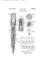
Whileone embodiment of the invention is illustrated -in the accompanying drawings lit ing mechanism isf to be understood that'this 'embodiment merely as anillus'trfation ofthe under- Aprimilespf the' inventionso 'that they in the art 'and is' not intended as Imiitin the invention' to the specific form disclose therein. 'L t' Imsaid drawings:
pa y fragmentary, y
'e position from that shown 'mEig 1 [of the elements shown in lead magazine adapted to Vreceive a plurality unitary shell may operable memben the tube partite. .end C art at one end ide tip' to support part of thelead l 'servesas amanual y o 4v.tate the magazine.
shown' `as upstanding nevertheless it might alsobe dependent,4 the skilled' ent dome f the dome-is'within thecontem f w -invnhicn', F1 1 '1s a v'ertlcal `section 'of thepencl" v#themagasin Fig; -2 1s a fragmentary sectionalyiew Fig` 3. is a section of Fig; 1 on the line `3 8. l Fig.4 is a section of'Fig. l on the line 4-4.
Fig. 5 is a fragmentary Iplg.` 1,. I Fig. 6 -shows the manner of assembling someof the parts.'
o Contn prises a plurality of she strips A'- 'united along their vertical edagles and enclosing the major portion of a le fee in element. 'While the shell A in e preferred embodiment consists ofa plurality of strips as indicated, the invention-is not to the use of`a plurality of 4 shell'4 parts since a be used as wlllbe readily understood. irrespective as. to whether the shell or casing is unita or built u :from a number of strips a feed tube 4B avin -a thread B' formed. shammi-is 10eme wie 'n the shell bore.
detail view of one ynow by way oft-a detailed -.de scripton, a s ell or casnglll preferably coml The writing endA of the tube B 'is tapered to form a guide tip BQ'the tube bein carried beyond the shell so as to give a finis ed appearance to the pencil and to de and support the lead which turedzend. Q
. A' lead ma azlne C, adapted'to be inserted adapted t0 be :distorted by s reading thej split-,parts a reentrant. ome sha rule E, 'w the usual manner.- `of thenraga'zine zine and ferrule'to ther s0 at the ferrule table member to -ro- "le' the dome D -is m e 41n beingforced over the outside of the as will b y; 'und rstood.
'Olflthe -has one end splitto'form a bi-` espesa! e isdesigned to project through its apered part D formed in the eraser ferich in turncarlies the eraser F in The distortion of the end' securely locks the maga-l` ofthe: pencil elements in a differentalso one .end split to the bipartite clutch Gif-in themanner shown'm Figli, the
parts being shaped to fit the leads and t0 aford a substantial frictional enlga ement with the lead to firmly yet resilient y supthe magazine through this clutch.
The magazine has a vertical ide slot H and a follower J is arranged to ar against the rearmost lead to `feed the series of leads toward the tip. This follower preferably consists of a cylinder havin one or more win J projecting through t e s lot and engaging the threads of the feed tube B. The rotation of the eraser ferrule and the attached tube C .carries the follower around, and the en agement of the follower wings in the tube t reads feeds the follower toward the writing end of the neil which inturn xects the foremost l of the series from etip B the desired distance.V
It will be observed that the eraser ferrule, magazine and follower form a unitary structure which may be removed bodily from the feed tube by rotating the tube and follower until the follower wings become disengaged from the tube. The magazine on removal from the shell, may be filled with the requisite number of leads. As has already been indicated the shell or casing consists of a plurali-ty of shell parts united to each other along vertical edges and this construction is preferred as peculiarly lending litself to the expgditious method of production shown in n view of the fact that the lead feeding mechanism consists of a unitary assemblage `of elements cooperating with a feed tube it is contemplated `simultaneously forming the shell parts for a plurality of pencils instead of forming each shell individually. The present invention contemplates forming a plurality of preferably parallel recesses or `grooves in a rough shell part L, inserting a eed tube B preferably in each of these Vrecesses, forming a plurality of parallel recesses in a second rough shell part L, uniting the two and then shaping the Arough shell to give the desired shape to the individual pencil. The shaping operation may simply consist of running a V shaped groove between the recesses to orm faces M. The spacing of the grooves or recesses is preferably so arranged that the shaping operation will also separate the individual pencils. The separation of the pencils from each other by a V shaped oove vin the manner indicated results in e conventional pencil having a hexagonal cross section. However the resent invention is obviously not limited to t e production of a pencil having a hexagonal cross section but e shape of the grooving tool a threaded feed tube secure the may be so selected as to afford other shapes of pencil.
The lead propelling mechanism is assembled by inserting the lead follower J in the magazine C, then forcing the donnef D over the bipartite end and then 'a pl ing/pressure on the dome cap to spread tlie ipartite end, the annular rim or shoulder N formed in the magazine serving to limit the downward movement of the dome so that a sli ht clearance remains between the end of t e m azineand dome and permitting the bipartlte ends t'o be readily spread to lock with the dome. The assembled feedy mechanism ma be then readily inserted in the feed tube g and removed as desired to refill the magazine vthrough the clutch G altho h it is quite evident that the magazinemig t be refilled b pushing the leads through the apertured en s of thetip B of the assembled pencil.
When I speak in my claims of uniting a shell pant to another shell part it is to be understood that either oreach of the shell parts ma consist of a plurality of shell parts.
t is claimed:
l. The method of manufacturing a mechanical pencil which compri the `step of first forming a recess in a shell part, coating said recess with an adhesive and then forcing an internally and externally grooved feed tube into said recess to force the adhesive into the grooves of the feed tube to form shell having grooves pressed in to the tube to form threads on the interior and grooves on the exterior, the feed tube tapered at the forward end and the tapered part projecting beyond the shell, and an adhesive inder be tween the tube and the shell.
3. A mechanical pencil comprising a shell consistin of longitudinally divided shell parts united along their lon itudinal edges, in the shell, `a tubular lead holder havin a guide slot within the feed tube, a rotata le member having a reentrant part to receive the rear end of the tubular lead holder, a lead follower within the lead holder having a wing engaging the guide slot and in threaded engagement with threads of the feed tube, one end of the feed tub being tapered to form a guide tip and the other end being spread into the reentrant part and locked thereto.
4. In a method of manufacturing mechanical pencils, the steps of rst forming a recess in a shell part, coating the recess with an adhesive, then forcing a feed tube having an external spiral lgroove into the recess and then applying a second shell part to the Y 5. The method of assembling the parts of a mechanical pencil which comprises the step of first placing the end of a tubular lead magazine in a flared re-entrant .part of an eraser holder, then spreading the lead magazine diametrically Within the re-entrant part of the eraser holder to lockthe two together and means comprising a manually operable member at the end of the pencil remote from the writing end for moving the lead.
8. A mechanical pencil combining a cas- Y ing, a feed tube having displaced portions forming an external groove in the feed tube and an internal bead on the interior thereof snugly fitted in the casing and held against rotation thereby, a slotted rotatable lead holder located Within the feed tube, and a manually operable member at the end of the tube remote from the Writing end the rotatable lead holder extending beyond the end of the feed tube and casing.
9. A mechanical pencil combining a casing having a longitudinal bore, a feed tube snugly fitted in the bore having portions thereof displaced, the displaced portions forming an external groove in the feed tube and an internal bead on the interior thereof, a slotted rotatable feed member concentrically, located Within the feed tube and projecting beyond said feed tube at the end of the pencil remote from the Writing end, a manually operable member secured to the projecting end of the feed member remote from the Writing end, and an exposed guide tip at the writing end of the pencil.
10. A mechanical pencil combining a casing having a longitudinal bore coextensive therewith, an` exposed guide tip at the Writing end of the pencil, a feed tube having portions thereof displaced, the displaced portions forming` an external groove and an internal bead, the feed tube being snugly fitted in a portion of the bore, a rotatable lead holder within the feed tube projecting beyond the end of the tube at the end of the pencil remote from the writing end, the end 0f the writing end of the lead holder being located Within the tapered guide tip, and a manually operable member secured to the end of the lead holder remote from the Writing end and in sliding contact with a portion of the casing and one end of the threaded feed tube and guided thereby.
11. A mechanical pencil combining a casing, a feed tube having displaced portions to form threads Within the casing, a rotatable lead holder having a slot and located Withinv the feed tube and a member having a Wing projecting through the slot of the lead holder and engaging the threads of the feed tube to move the lead, the rotatable lead holder being in sliding contact with the threads of the feed tube and being guided thereby.
l2. A mechanical pencil combining a casing, a non-rotatable tapered lead guide tip at the Writing end of the pencil, a feed tube having displaced portions forming threads Within the casing bore and coextensive therewith, a slotted rotatable lead holder Within said threaded feed tube and projecting beyond the feed tube and a manually operable membei` at the end of the pencil remote from the Writing end secured to the projecting end of the rotatable slotted lead holder to rotate the same.
13. In a mechanical pencil combining a casing having a longitudinal bore, a tapered lead guide tip at the ivriting end of the pencil,
a threaded feed tube Within the casing bore, a slotted rotatable lead holder projecting beyond the end of the casing bore, and a manually operable member at the end of the pencil remote from the Writing end secured to the cud of the rotatable slotted lead holder projecting beyond the casing bore to rotate the same.
la. A mechanical pencil combining a casing having a longitudinal opening, a feed tube within the bore and relatively stationary with respect to the casing, a rotatable feed tube slotted on one side only concentrically located within the feed tube, a manually operable member secured to the rotatable feed tube at the end of the tube remote from the Writing end, and a rigid stationary tapered exposed guide tip at the writing end of the pencil, the end of the slotted tube at the writing end of the pencil being wholly located Within the guide tip.
15. A mechanical pencil combining a casing, having a longitudinal opening, a feed tube having displaced portions forming threads, the feed tube terminating in a tapered rigid exposed guide tip at the writing end of the pencil, and projecting beyond the casing, a rotatable member having a slot within the feed tube, a member having a wing projecting through the slot of the last named member and engaging the threads of the feed tube, to move the lead on rotation of the rotatable member.
1G. A mechanical pencil combining a casing having a longitudinal opening, a feed tube having a displaced portion forming threads on the interior thereof, a4 rotatable lead holder` having a slot on one side thereof .van
which tapers to a slot of smaller Width near the writing end of the pencil located Within the feed tube and projecting beyond the casing, and a manually operable member secured to the projecting end of the rotatable lead hoider at the end of the pencil remote from the writing end.
17. A mechanical pencil combining a casing having a longitudinal opening, a stationary tapered guide tip at the Writing end of the casing, a feed tube having portions thereof displaced, the displaced portions forming an external groove and internal thread, the feed tube being located within a portion of the casing opening, a rotatable lead holder having one end located Within the guide tip and the other end projecting beyond the feed tube, and a manually operable member secured to the projecting end of the lead holder remote from the Writing end and in sliding contact with a portion of the casing and adapted to be guided thereby.
18. A mechanical pencil comprising a casing having a longitudinal internally-threaded bore and terminating in a tapered rigid guide tip at the Writing end of the pencil, a rotatable member having a slot Within the bore, a member having a wing projectin through the slot ofthe rotatable member an enga 'ng the threads of the bore to move the lea on rotation of the rotatable member.
Signed at New York city in the county of New York and State of `New York this 27th day of March, A. D. 1923.
PAUL S. HAUTON.
ADISCLJMMEF! 1,853,560r-Ifaul S. Hautoa, Newark, N. J. MECHANICAL PENCIL. Patent dated April 12, 1932. Dlsclauner filed November 2, 1935, by the assignee, Scripta llflanufactur'ing Company. Hereby'entors this disclaimer to claim 5 of said Letters Patent. [Qcwl GazetteA November 26, 1.935.]
Priority Applications (1)
| Application Number | Priority Date | Filing Date | Title |
|---|---|---|---|
| US627188A US1853560A (en) | 1923-03-23 | 1923-03-23 | Mechanical pencil |
Applications Claiming Priority (1)
| Application Number | Priority Date | Filing Date | Title |
|---|---|---|---|
| US627188A US1853560A (en) | 1923-03-23 | 1923-03-23 | Mechanical pencil |
Publications (1)
| Publication Number | Publication Date |
|---|---|
| US1853560A true US1853560A (en) | 1932-04-12 |
Family
ID=24513588
Family Applications (1)
| Application Number | Title | Priority Date | Filing Date |
|---|---|---|---|
| US627188A Expired - Lifetime US1853560A (en) | 1923-03-23 | 1923-03-23 | Mechanical pencil |
Country Status (1)
| Country | Link |
|---|---|
| US (1) | US1853560A (en) |
-
1923
- 1923-03-23 US US627188A patent/US1853560A/en not_active Expired - Lifetime
Similar Documents
| Publication | Publication Date | Title |
|---|---|---|
| US1853560A (en) | Mechanical pencil | |
| US2565556A (en) | Ball point fountain pen | |
| US10974539B2 (en) | Rotary feeding mechanism for rod-shaped body | |
| US1679382A (en) | Pencil | |
| US2287364A (en) | Mechanical pencil | |
| US2182846A (en) | Mechanical pencil | |
| US1853561A (en) | Mechanical pencil | |
| US1849210A (en) | Mechanical pencil | |
| US2129655A (en) | Pencil | |
| US1540018A (en) | Pencil | |
| US3135242A (en) | Ball-point pens | |
| US1372354A (en) | Pencil | |
| US1693578A (en) | Magazine pencil | |
| US1806632A (en) | Pencil | |
| US2624313A (en) | Mechanical pencil and collet therefor | |
| US2406171A (en) | Mechanical pencil | |
| US1910552A (en) | Mechanical pencil | |
| US1556701A (en) | Mechanical pencil | |
| US3072102A (en) | Mechanical pencil | |
| US2184864A (en) | Mechanical pencil | |
| US1913662A (en) | Pencil | |
| US1590330A (en) | Writing-lead-pointing device | |
| US1410666A (en) | Pencil | |
| US1369347A (en) | Lead-pencil | |
| US1574457A (en) | Mechanical pencil |