US1853559A - Car door opener - Google Patents
Car door opener Download PDFInfo
- Publication number
- US1853559A US1853559A US375691A US37569129A US1853559A US 1853559 A US1853559 A US 1853559A US 375691 A US375691 A US 375691A US 37569129 A US37569129 A US 37569129A US 1853559 A US1853559 A US 1853559A
- Authority
- US
- United States
- Prior art keywords
- door
- car
- shaft
- car door
- door opener
- Prior art date
- Legal status (The legal status is an assumption and is not a legal conclusion. Google has not performed a legal analysis and makes no representation as to the accuracy of the status listed.)
- Expired - Lifetime
Links
- 241001155961 Baris Species 0.000 description 1
- 238000010276 construction Methods 0.000 description 1
Images
Classifications
-
- E—FIXED CONSTRUCTIONS
- E05—LOCKS; KEYS; WINDOW OR DOOR FITTINGS; SAFES
- E05F—DEVICES FOR MOVING WINGS INTO OPEN OR CLOSED POSITION; CHECKS FOR WINGS; WING FITTINGS NOT OTHERWISE PROVIDED FOR, CONCERNED WITH THE FUNCTIONING OF THE WING
- E05F11/00—Man-operated mechanisms for operating wings, including those which also operate the fastening
- E05F11/53—Man-operated mechanisms for operating wings, including those which also operate the fastening for sliding windows, e.g. vehicle windows, to be opened or closed by horizontal movement
Definitions
- the invention relates to improvements in car door openers and an object of the invention is to provide-a device which can be readily applied on the well known type of box car 5 and which will permit an attendant to easily and quickly open the outer sliding door of the car without having to resort to utilizing the customary too-ls employed and without inL any way mutilating or otherwise damaging the 10 door.
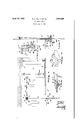
- Fig. 1 is a side View of a car door equipped with our invention.
- Fig. 2 is an enlarged detailed verticalsec- 20 tional view at 2-2 Figure 1.
- Fig. 3 is an enlarged detailed horizontal sectional view at 3 3 Figure 1.
- Fig. 4 is a perspective View of the guide shoe employed. f
- Fig. 5 is an enlarged detailed vertical sectional view through the hand wheel and associated parts, the shaft and lever being shown in side elevation.
- the box car 1 is provided with the customary outer door 2 which is slidably guided for opening and closing movement between the tracks 3 and 4. It is quite often found that after a car has been in use for a period of time the outer door does not slide freely and in such. cases, crow bars or pinch'bars have been resortedto to force the'dooropen.: I
- a hand wheell 18 which permits the shaft to be readily rotated by an attend-E85 ant and if the door will open readily one simply turns the hand wheel in the propelI direction andy the rack bar pulls the door open.
- a lever 19 whichhas the upper end thereof forkedA and spanning a collar 20 rotatably mounted on the lower end of the shaftythe collar being supported by a pin 21:;95 passing through the shaft and being connected to the forked ends of the lever by side pins 22 and23. ⁇ f .l v Y f Y
- the lever normally hangs down in the vertical position so that it will not rbe in the road-21.100
- the lever when the car is in transit.
- the lever can be used like aratchet as the upper end thereoi can l'ireely turn on the shaft and the lever can be droppeddown when desired to escape Vfrom one set of pins and then raised to enter between another set of pins.
- the variousgparts have f all vbeen designed so that they do not project very far from the side wallfof the car and consequently there i is no possibilit-y of them beingin the road -whenvthe car is in transit.
Landscapes
- Elevator Door Apparatuses (AREA)
Description
April 12, 1932.
R. L. HALPIN ET AL CAR DOOR OPENER Filed July 3, 1929 Patented Apr. 12, 1932 ROBERT L. HALPIN AND HARRY E. Brani), or WINNIPEG. MANITOBA, cANAiin'.
UNITED STATES 'PATE N Tfl OFFICE( GAR Doon- OPENER Application led July 3, 1929, Serial No. 375,691, and 'in Canada, May 13`, 1329.-
The invention relates to improvements in car door openers and an object of the invention is to provide-a device which can be readily applied on the well known type of box car 5 and which will permit an attendant to easily and quickly open the outer sliding door of the car without having to resort to utilizing the customary too-ls employed and without inL any way mutilating or otherwise damaging the 10 door.
With the above more important object in view the invention consists essentially in the arrangement and construction of parts hereinafter more particularly described, reference 15 being had to the accompanying drawings in which Fig. 1 is a side View of a car door equipped with our invention. y
Fig. 2 is an enlarged detailed verticalsec- 20 tional view at 2-2 Figure 1.
Fig. 3 is an enlarged detailed horizontal sectional view at 3 3 Figure 1.
Fig. 4 is a perspective View of the guide shoe employed. f
Fig. 5 is an enlarged detailed vertical sectional view through the hand wheel and associated parts, the shaft and lever being shown in side elevation.
In the drawings like characters of reference indicate corresponding parts in the several figures. p
Difficulty is experienced at the present time in opening the outer door of box cars and according kto present practice crow bars and other tools are used to do the work and very often both the door and the side of the ciar are mutilated or damaged. According to our invention we equip the carwith a manually operated device embodying a hand wheel which when turned in the proper direction, will open the door easily and quickly and without any possibility of damaging either the car or the door.
The box car 1 is provided with the customary outer door 2 which is slidably guided for opening and closing movement between the tracks 3 and 4. It is quite often found that after a car has been in use for a period of time the outer door does not slide freely and in such. cases, crow bars or pinch'bars have been resortedto to force the'dooropen.: I
These are usually applied at the lower right handcorner of the door and they have a natural tendency to 'cant the door so that it binds-"1355 This brings a heavy strain on the wooden parts of the door when it isbeing openedand the crow baris apt to puncture the car which allows 'a commodity such as grainto escape crit is apt'to damage'either the-car or the door.v i t In carrying out'our invention .we vprovide a shaft 5 placed at some distance from the door as shown, the shaft havingits lower end rotatably mountedk in a sleeveilike bearingffi securely ybolted to the under side ofthe outer .sill 8 of the car floor 9v and the upperl end thereof-rotatably mounted in similar bearings'lO and 11 suitablyy bolted to the walll of the car. On the shaft between the bearings-imp 10 .and 11, wemountfa shoe 12, the base ofy which is spaced from the wall of they car to permitthe shoetorotate aV limited amount on'V the shaft'. This slice receives slidably-one end ofa rackbarf 13.which has the teeth 1435115 thereof extending away from the face of the car and continuously. in mesh with the pinion 15 permanently secured'to the shaft. The other end of the rack bar is lconnectedby a pivot bolt 16 to opposing lugs 17 suitably andzliso hrmlyrattached to the adjacent side of the door 2. K
To the lower end of the shaft we secure permanently a hand wheell 18 which permits the shaft to be readily rotated by an attend-E85 ant and if the door will open readily one simply turns the hand wheel in the propelI direction andy the rack bar pulls the door open. However, in practice, it is found that some doors are heavier to open than othersio and in order to open such a door we have provided a lever 19 whichhas the upper end thereof forkedA and spanning a collar 20 rotatably mounted on the lower end of the shaftythe collar being supported by a pin 21:;95 passing through the shaft and being connected to the forked ends of the lever by side pins 22 and23.` f .l v Y f Y The lever normally hangs down in the vertical position so that it will not rbe in the road-21.100
2f v k1,853,559
when the car is in transit. One can readily swing the lever upwardly to the horizontal position and in such position, it is adapted to pass between adjacent spaced stop pins 24 5 extending downwardly from the under side of the hand wheel. By utilizing the lever, one can easily open a tight door and according to the arrangement, the lever can be used like aratchet as the upper end thereoi can l'ireely turn on the shaft and the lever can be droppeddown when desired to escape Vfrom one set of pins and then raised to enter between another set of pins.
The variousgparts have f all vbeen designed so that they do not project very far from the side wallfof the car and consequently there i is no possibilit-y of them beingin the road -whenvthe car is in transit.
What we claim as our invention is The combinationy with the outer laterally slidabledoor of'fa boX car, of a vertically eX- tending'shaiitv rotatably carried -by the side waill of the car andlocated a distance away from the -dooropening greater than the width 1 '2b-of the fdoor, ka pinion permanently secured to the upper end of the shaft, a shoe pivotally mountedv on the shaft and vspanning the pinion,- a horizontally disposed rack bar having one end entered between the. shoe and the `:"1` pinion-andY .slidably carried by the shoe with the teeth .thereof engaged with the pinion Y and thewother endpivotally fastened by a vertical .pivot pin tothe adjacent end of the door in a locationtowards the upper end of 85 'thedoorand` means carried by the lower end ofthe shaft in a locationl beneath the car sill for manually turning `the same.
Y ruary 1929. y v 40' ROBERT L. HALPIN.V
.,HARRY `EABI'ERD.. Y
Bil.
Applications Claiming Priority (1)
| Application Number | Priority Date | Filing Date | Title |
|---|---|---|---|
| CA1853559X | 1929-05-13 |
Publications (1)
| Publication Number | Publication Date |
|---|---|
| US1853559A true US1853559A (en) | 1932-04-12 |
Family
ID=4174319
Family Applications (1)
| Application Number | Title | Priority Date | Filing Date |
|---|---|---|---|
| US375691A Expired - Lifetime US1853559A (en) | 1929-05-13 | 1929-07-03 | Car door opener |
Country Status (1)
| Country | Link |
|---|---|
| US (1) | US1853559A (en) |
Cited By (4)
| Publication number | Priority date | Publication date | Assignee | Title |
|---|---|---|---|---|
| US2640440A (en) * | 1949-11-18 | 1953-06-02 | Entpr Railway Equipment Co | Closure for hopper of hopper type railway cars |
| US3468063A (en) * | 1968-04-19 | 1969-09-23 | Hennessy Products | Double sliding door actuator |
| US4541202A (en) * | 1984-03-16 | 1985-09-17 | Daryl Dockery | Sliding door operator and lock |
| US20070107588A1 (en) * | 2005-11-17 | 2007-05-17 | Jay Menefee | Method and apparatus for manufacturing wad-less ammunition |
-
1929
- 1929-07-03 US US375691A patent/US1853559A/en not_active Expired - Lifetime
Cited By (5)
| Publication number | Priority date | Publication date | Assignee | Title |
|---|---|---|---|---|
| US2640440A (en) * | 1949-11-18 | 1953-06-02 | Entpr Railway Equipment Co | Closure for hopper of hopper type railway cars |
| US3468063A (en) * | 1968-04-19 | 1969-09-23 | Hennessy Products | Double sliding door actuator |
| US4541202A (en) * | 1984-03-16 | 1985-09-17 | Daryl Dockery | Sliding door operator and lock |
| US20070107588A1 (en) * | 2005-11-17 | 2007-05-17 | Jay Menefee | Method and apparatus for manufacturing wad-less ammunition |
| US7814820B2 (en) | 2005-11-17 | 2010-10-19 | Jay Menefee | Method and apparatus for manufacturing wad-less ammunition |
Similar Documents
| Publication | Publication Date | Title |
|---|---|---|
| US2142236A (en) | Load discharging car | |
| US1615120A (en) | Grain-car-door latch | |
| US1853559A (en) | Car door opener | |
| US1892589A (en) | Decking structure | |
| US3796007A (en) | Door moving structure | |
| US3468063A (en) | Double sliding door actuator | |
| US3079987A (en) | Door construction | |
| US433256A (en) | Car-door | |
| DE641943C (en) | Door for motor vehicles | |
| US1489959A (en) | Car door | |
| US1355874A (en) | Grain-door | |
| US2206599A (en) | Sliding vehicle door | |
| US1041901A (en) | Operating mechanism for car-doors. | |
| GB384631A (en) | Locks for hinged doors of vehicles | |
| WO2007036345A2 (en) | Refrigerator | |
| US935450A (en) | Box-car door. | |
| DE807282C (en) | Handlebar swing door, especially for rail or road vehicles | |
| US1440107A (en) | Car door | |
| US4189869A (en) | Railway car door moving means | |
| DE448875C (en) | Side window for closed cars | |
| US1628920A (en) | Door closure for railway cars | |
| US1569029A (en) | Grain door for railway cars | |
| DE835450C (en) | Horizontally divided window for rail vehicles | |
| US603362A (en) | Car-door fastening | |
| US1584289A (en) | Sliding door |