US1853553A - Spacing strip - Google Patents
Spacing strip Download PDFInfo
- Publication number
- US1853553A US1853553A US512414A US51241431A US1853553A US 1853553 A US1853553 A US 1853553A US 512414 A US512414 A US 512414A US 51241431 A US51241431 A US 51241431A US 1853553 A US1853553 A US 1853553A
- Authority
- US
- United States
- Prior art keywords
- protuberances
- strip
- spacing
- film
- perforations
- Prior art date
- Legal status (The legal status is an assumption and is not a legal conclusion. Google has not performed a legal analysis and makes no representation as to the accuracy of the status listed.)
- Expired - Lifetime
Links
- 125000006850 spacer group Chemical group 0.000 description 13
- 239000007788 liquid Substances 0.000 description 5
- 238000004049 embossing Methods 0.000 description 4
- 239000000463 material Substances 0.000 description 4
- 238000010276 construction Methods 0.000 description 2
- 239000012530 fluid Substances 0.000 description 2
- 238000000034 method Methods 0.000 description 2
- 229920002160 Celluloid Polymers 0.000 description 1
- 230000006978 adaptation Effects 0.000 description 1
- 230000006866 deterioration Effects 0.000 description 1
- 230000000266 injurious effect Effects 0.000 description 1
- 239000000126 substance Substances 0.000 description 1
- XLYOFNOQVPJJNP-UHFFFAOYSA-N water Substances O XLYOFNOQVPJJNP-UHFFFAOYSA-N 0.000 description 1
Images
Classifications
-
- G—PHYSICS
- G03—PHOTOGRAPHY; CINEMATOGRAPHY; ANALOGOUS TECHNIQUES USING WAVES OTHER THAN OPTICAL WAVES; ELECTROGRAPHY; HOLOGRAPHY
- G03D—APPARATUS FOR PROCESSING EXPOSED PHOTOGRAPHIC MATERIALS; ACCESSORIES THEREFOR
- G03D13/00—Processing apparatus or accessories therefor, not covered by groups G11B3/00 - G11B11/00
- G03D13/02—Containers; Holding-devices
- G03D13/08—Devices for holding exposed material; Devices for supporting exposed material
- G03D13/14—Devices for holding exposed material; Devices for supporting exposed material for holding films in spaced convolutions
- G03D13/142—Devices for holding exposed material; Devices for supporting exposed material for holding films in spaced convolutions with a spacing strip
Definitions
- Patented Apr. 12, 1932 PATENT OFFICE LE ROY C. DAVIDGE, F HOLLYWOOD, CALIFORNIA SPACING STRIP Application led January 30, 1931.
- My invention relates to means for spacing the layers ofcoiled or otherwise superposed j j films and the like, for the purpose of treating them in liquid baths.
- first to provide an improved type of spacing strip that has protuberances on each face thereof at each of its edges, and which is otherwise particularly suitable for the purpose mentioned;
- second to provide a spacer of the above character wherein the contacts between the protuberances and the surfaces being treated, cannot have any injurious effect;
- fourth to provide a spacer of the above na- 3 ture wherein the protuberances cannot close the sprocket perforations of a motion picture film used therewith, to more than a slight extent, thereby permitting all of said holes to materially assist in maintaining a free circulation of fluid to all parts of the film;
- fifth to provide a spacer of the character
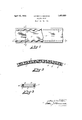
- Figure 1 is a plan view of a portion of my improved spacing strip associated with an ordinary type of motion picture film therebeneath, the two being in the relative position Serial No. 512,414.
- FIG. 2 is a longitudinal section of the 5 above film and spacer taken on the line 2-2 of Fig. 1, and with an additional film on top of the other two in the same relative position, thereby illustrating how two superposed films Y magy be separated by my improved means; 6'3 an Figure 8 is a cross-section taken on the line 3--3 of F ig. l, with said additional photographic film on top of the other two, as in Fig. 2.
- My method of spacing such films includes the use of a spacing strip 7 having a longitudinal series of spaced protuberances 8 upon each face, adjacent each of its edges.
- the protuberances of each series, on each face of the film are positioned between corresponding protuberances of the same dimensions on the other face. They may be formed, most conveniently, by embossing a strip of suitable material. n this way the protuberances of one face will appear as depressions 9, when viewing the other face of the film.
- the two series of protuberances on each face of the spacer are staggered in transverse relation to each other, in order to enable them to break up transverse How paths of liquid circulating between the spacer and films 5 and l0 that are spaced thereby.
- Each of the two series of protuberances, on each face of the spacer may be so located that, when the spacer is placed between layers of a motion picture film, the contacts between the protuberances andthe film will lie only in the track of sprocket perforations 6.
- This track is not useful for any photographic purpose other than for affording means for causing mechanical movement of the film, and any differences or variations of treatment by reason of these contacts in said track is of no importance.
- protuberances 8 at the points where they contact with the surface of motion picture films being spaced, is made such that they cannot enter perforations 6', or more than partially close them.
- longitudinal dimension of the protuberances at the points of contact is made greater than the width (longitudinal dimension) of the perforations.
- transverse width of the protuberances at the points of Contact is made less than the length (transverse dimension) of the perforations. Therefore, if any protuberance happens to lie opposite a sprocket perforation, it will bridge the latter longitudinally, and leave an open space for circulation of fluid through-the perforations at each side of the protuberance.
- spacer 7 is preferably made the same as that of the film being treated.
- a plain celluloid strip is very light, strong, cheap, and inert to the chemicals used in photographic processes.
- the softened strip cools and sets almost immediately after passing through the embossing rolls, and it may be used many times in the treatment ofy photographic films without deterioration.
- a n article of the character described comprising.; a spacing strip having on a face thereof opposed longitudinal rows of spaced protuberances adjacent its lateral edges, whereby it is adapted to maintain a spaced relation to a superposed strip; the protuberances of said rows being staggered with respect to each other, transversely of the strip, thus adapting them to break up currents flowing transversely between said two strips.
- An article of the character described comprising; a spacing strip having opposed longitudinal rows of spaced protuberances adjacent its lateral edges on each of its faces, whereby it is adapted to maintain a spaced relation to a superposed strip at each side; the protuberances of said rows on each face being staggered with respect to each other, transversely of the strip, thus adapting them to break up currents flowing transversely between said faces and said superposed strips.
- a spacing strip having a longitudinal row of spaced protuberances on a face thereof adjacent each of its lateral edges whereby it is adapted to maintain a spaced relation to a superposed film strip having correspondingly positioned rows of sprocket perforations therethrough; said protuberances being so shaped, and being of such dimensions, as to render them incapable of engaging said perforations.
- a spacing strip having a longitudinal row of spaced protuberances on a face thereof adjacent cach of its lateral edges, where by it is adapted to maintain a spaced relation to a superposed film strip having correspondingly positioned rows of sprocket perforations therethrough; said protuberances having rounded surfaces, and longitudinal and transverse dimensions that differ materially from the corresponding dimensions of the perforations.
- a spacing strip having a longitudinal row of spaced protuberances on a face thereof acent each of its lateral edges, whereby it is adapted to maintain a spaced relation to CTL a superposed film strip having correspondingl7 positioned rows of sprocket perforations therethrough; said protuberances having rounded surfaces, and having longitudinal dimensions greater than, and lateral dimensions less than, the corresponding dimensions of said perforations.
Description
April 12, 1932. LE ROY c. DAVIDGE SPACING STRIP Filed Jan. 30, 1931 INI/ENTo/e; Z'efoy CLDavLoQe, By l/eff' A TORNEY.
Patented Apr. 12, 1932 PATENT OFFICE LE ROY C. DAVIDGE, F HOLLYWOOD, CALIFORNIA SPACING STRIP Application led January 30, 1931.
In this specification, and the accompanying drawings, I shall describe and show a preferred form of my invention, and specifically mention certain of its more important ob- V jects.` I do not limit myself to the forms disclosed, since various changes and adaptations may be made therein without departing from the essence of my invention as hereinafter claimed; and objects and advantages,
other than those specifically mentioned, are
included within its scope.
My invention relates to means for spacing the layers ofcoiled or otherwise superposed j j films and the like, for the purpose of treating them in liquid baths. Among its principal objects are first, to provide an improved type of spacing strip that has protuberances on each face thereof at each of its edges, and which is otherwise particularly suitable for the purpose mentioned; second, to provide a spacer of the above character wherein the contacts between the protuberances and the surfaces being treated, cannot have any injurious effect; third, to provide such a spacer wherein the spacing means cannot engage the sprocket perforations of a motion picture film, thereby avoiding any possibility of such films and spacer becoming locked together; fourth, to provide a spacer of the above na- 3 ture wherein the protuberances cannot close the sprocket perforations of a motion picture film used therewith, to more than a slight extent, thereby permitting all of said holes to materially assist in maintaining a free circulation of fluid to all parts of the film; fifth, to provide a spacer of the character described, wherein the protuberances are so shaped and so located as to adapt them to break up the Y. flow paths of liquid that is forced between it and the layers of an associated lm; and, sixth, to accomplish the above by means of a very simple, inexpensive, and thoroughly practical device.
My objects are attained in the manner illustrated in the accompanying drawings, in
which Figure 1 is a plan view of a portion of my improved spacing strip associated with an ordinary type of motion picture film therebeneath, the two being in the relative position Serial No. 512,414.
they assume when they are coiled together, or when they are otherwise superposed for helpurpo-se of treating the film in a liquid Figure 2 is a longitudinal section of the 5 above film and spacer taken on the line 2-2 of Fig. 1, and with an additional film on top of the other two in the same relative position, thereby illustrating how two superposed films Y magy be separated by my improved means; 6'3 an Figure 8 is a cross-section taken on the line 3--3 of F ig. l, with said additional photographic film on top of the other two, as in Fig. 2.
Similar reference numerals refer to similar parts throughout the several views.
In a joint application filed January 23,
1929 (Serial No. 334,438), by Arthur E. Reeves and myself, we disclosed, but did not claim per se, a form of spacing st-rip having certain features in common with the spacer herein disclosed for the first time. Subsequently I became the sole owner of said prior invention, and of all rights to accrue under said application, as per an assignment duly recorded in the Patent Office. I now desire to secure protection upon the spacing strip disclosed in said prior application, as well as upon the subsequent improvements made thereon, as herein set forth and claimed. My present invention will be found to be particularly applicable to the treatment of coiled photographic films in liquid baths, but may be used in connection with the treatment of superposed uncoiled films. By far the greater part of the films that are handled and treated superposed, comprise motion picture films having spaced sprocket perforations at each edge. Such a film is shown in the drawings at 5, the sprocket perforations being indicated at 6.
My method of spacing such films, includes the use of a spacing strip 7 having a longitudinal series of spaced protuberances 8 upon each face, adjacent each of its edges. The protuberances of each series, on each face of the film, are positioned between corresponding protuberances of the same dimensions on the other face. They may be formed, most conveniently, by embossing a strip of suitable material. n this way the protuberances of one face will appear as depressions 9, when viewing the other face of the film. The two series of protuberances on each face of the spacer are staggered in transverse relation to each other, in order to enable them to break up transverse How paths of liquid circulating between the spacer and films 5 and l0 that are spaced thereby.
Each of the two series of protuberances, on each face of the spacer, may be so located that, when the spacer is placed between layers of a motion picture film, the contacts between the protuberances andthe film will lie only in the track of sprocket perforations 6. This track is not useful for any photographic purpose other than for affording means for causing mechanical movement of the film, and any differences or variations of treatment by reason of these contacts in said track is of no importance. y
The dimensions of protuberances 8, at the points where they contact with the surface of motion picture films being spaced, is made such that they cannot enter perforations 6', or more than partially close them. Thus the longitudinal dimension of the protuberances at the points of contact is made greater than the width (longitudinal dimension) of the perforations.; and the transverse width of the protuberances at the points of Contact is made less than the length (transverse dimension) of the perforations. Therefore, if any protuberance happens to lie opposite a sprocket perforation, it will bridge the latter longitudinally, and leave an open space for circulation of fluid through-the perforations at each side of the protuberance.
I prefer to make the spacing of the protuberances a considerable multiple of the perforation spacing. By the use of this expedient the protuberances cannot come opposite the perforations, except at considerable in tervals. The width of spacer 7 is preferably made the same as that of the film being treated. v i I have foundv that my improved form of spacer can be made very conveniently from a plain celluloid strip, by embossing it im mediately after it has been passed through hot water, and become softened thereby. Such a strip is very light, strong, cheap, and inert to the chemicals used in photographic processes. The softened strip cools and sets almost immediately after passing through the embossing rolls, and it may be used many times in the treatment ofy photographic films without deterioration.
Having thus fully described my invention, ina manner that will make its construction and operation clear to those familiarY with the art involved, I claim:
1. A n article of the character described, comprising.; a spacing strip having on a face thereof opposed longitudinal rows of spaced protuberances adjacent its lateral edges, whereby it is adapted to maintain a spaced relation to a superposed strip; the protuberances of said rows being staggered with respect to each other, transversely of the strip, thus adapting them to break up currents flowing transversely between said two strips.
2. An article of the character described, comprising; a spacing strip having opposed longitudinal rows of spaced protuberances adjacent its lateral edges on each of its faces, whereby it is adapted to maintain a spaced relation to a superposed strip at each side; the protuberances of said rows on each face being staggered with respect to each other, transversely of the strip, thus adapting them to break up currents flowing transversely between said faces and said superposed strips.
3. An article as set forth in claim 2, wherein the respective rows of protuberances on opposite faces of the spacing strip are o posed, and the protuberances are staggered; and wherein the protuberances are embossed from the material of the strip.
4. An article as set forth in claim 2, wherein the respective rows of protuberances on opposite faces of the spacing strip are o posed, and the protuberances are staggered); and wherein the protuberances are formed with surfaces of double curvature embossed from the material of the strip.
5. An article as set forth in claim 2, wherel in the respective rows of protuberances on opposite faces of the spacing strip are opposed, and the protuberances are staggered; and wherein the protuberances are ellipsoidal with their major axes approximately parallel to the edges of the strip, and are formed by embossing from the material of the strip.
6. A spacing strip having a longitudinal row of spaced protuberances on a face thereof adjacent each of its lateral edges whereby it is adapted to maintain a spaced relation to a superposed film strip having correspondingly positioned rows of sprocket perforations therethrough; said protuberances being so shaped, and being of such dimensions, as to render them incapable of engaging said perforations.
7 A spacing strip having a longitudinal row of spaced protuberances on a face thereof adjacent cach of its lateral edges, where by it is adapted to maintain a spaced relation to a superposed film strip having correspondingly positioned rows of sprocket perforations therethrough; said protuberances having rounded surfaces, and longitudinal and transverse dimensions that differ materially from the corresponding dimensions of the perforations.
8. A spacing strip having a longitudinal row of spaced protuberances on a face thereof acent each of its lateral edges, whereby it is adapted to maintain a spaced relation to CTL a superposed film strip having correspondingl7 positioned rows of sprocket perforations therethrough; said protuberances having rounded surfaces, and having longitudinal dimensions greater than, and lateral dimensions less than, the corresponding dimensions of said perforations.
9. A construction as set forth in claim 6 wherein the longitudinal spacing of the protuberances is materially different from Jche longitudinal spacing of said perforations of corresponding rows.
LE ROY C. DAVIDGE.
Priority Applications (2)
| Application Number | Priority Date | Filing Date | Title |
|---|---|---|---|
| US512414A US1853553A (en) | 1931-01-30 | 1931-01-30 | Spacing strip |
| GB32437/31A GB392907A (en) | 1931-01-30 | 1931-11-23 | A spacing strip for treating films in a liquid |
Applications Claiming Priority (1)
| Application Number | Priority Date | Filing Date | Title |
|---|---|---|---|
| US512414A US1853553A (en) | 1931-01-30 | 1931-01-30 | Spacing strip |
Publications (1)
| Publication Number | Publication Date |
|---|---|
| US1853553A true US1853553A (en) | 1932-04-12 |
Family
ID=24038980
Family Applications (1)
| Application Number | Title | Priority Date | Filing Date |
|---|---|---|---|
| US512414A Expired - Lifetime US1853553A (en) | 1931-01-30 | 1931-01-30 | Spacing strip |
Country Status (2)
| Country | Link |
|---|---|
| US (1) | US1853553A (en) |
| GB (1) | GB392907A (en) |
Cited By (1)
| Publication number | Priority date | Publication date | Assignee | Title |
|---|---|---|---|---|
| EP0456210A3 (en) * | 1990-05-09 | 1992-12-23 | Fuji Photo Film Co., Ltd. | Method for processing a silver halide photographic material and light-sensitive material for photographing |
-
1931
- 1931-01-30 US US512414A patent/US1853553A/en not_active Expired - Lifetime
- 1931-11-23 GB GB32437/31A patent/GB392907A/en not_active Expired
Cited By (2)
| Publication number | Priority date | Publication date | Assignee | Title |
|---|---|---|---|---|
| EP0456210A3 (en) * | 1990-05-09 | 1992-12-23 | Fuji Photo Film Co., Ltd. | Method for processing a silver halide photographic material and light-sensitive material for photographing |
| US5234802A (en) * | 1990-05-09 | 1993-08-10 | Fuji Photo Film Co., Ltd. | Method for processing a silver halide photographic material and light-sensitive material for photographing |
Also Published As
| Publication number | Publication date |
|---|---|
| GB392907A (en) | 1933-05-23 |
Similar Documents
| Publication | Publication Date | Title |
|---|---|---|
| SE7612131L (en) | DIAPOSITIVRAMAR | |
| US1853553A (en) | Spacing strip | |
| US3177793A (en) | Processor for photographic paper | |
| US1373493A (en) | Film-clip | |
| US1593301A (en) | Album | |
| US1549095A (en) | Game device | |
| US1598445A (en) | Spliced photographic film | |
| US3731349A (en) | Zip fastener chain | |
| US1852419A (en) | Film advancing appliance | |
| US626356A (en) | Photographic-film roll | |
| US1664855A (en) | Antisqueak device for vehicle brakes | |
| GB279594A (en) | Improvements in kinematograph film strips | |
| DE589199C (en) | Shutters made of metal supports that are flanged to the hinge on the edges and covered with insulating material | |
| SU25853A1 (en) | Fixture for restoring spoiled perforation in film | |
| US1457045A (en) | Apron for photographic developing equipment | |
| US1188824A (en) | Film holder and tray. | |
| SU1518A1 (en) | Gasket for flexible film processing | |
| DE457458C (en) | Metal film with protected image area | |
| USD69783S (en) | Design for a vanity case | |
| FR2354581A1 (en) | Microfilm destroying system by marking film surface - using two surfaced rollers between which film is passed | |
| DE439374C (en) | Multicolored grid and carrier of light-sensitive layer for the production of photographic or cinematographic images and process for their production | |
| GB190705762A (en) | Improvements in and relating to Closet Seat Guards. | |
| US1922725A (en) | Film coloring machine and method of coloring film | |
| DE371319C (en) | Focal plane shutter for photographic apparatus | |
| USD68522S (en) | Design for a shingle strip |