US1853552A - Treating hydrocarbons - Google Patents
Treating hydrocarbons Download PDFInfo
- Publication number
- US1853552A US1853552A US150630A US15063026A US1853552A US 1853552 A US1853552 A US 1853552A US 150630 A US150630 A US 150630A US 15063026 A US15063026 A US 15063026A US 1853552 A US1853552 A US 1853552A
- Authority
- US
- United States
- Prior art keywords
- tubes
- tube
- oil
- liquid
- heat
- Prior art date
- Legal status (The legal status is an assumption and is not a legal conclusion. Google has not performed a legal analysis and makes no representation as to the accuracy of the status listed.)
- Expired - Lifetime
Links
- 229930195733 hydrocarbon Natural products 0.000 title description 11
- 150000002430 hydrocarbons Chemical class 0.000 title description 11
- 239000003921 oil Substances 0.000 description 32
- 239000007788 liquid Substances 0.000 description 18
- 150000003839 salts Chemical class 0.000 description 16
- 238000005336 cracking Methods 0.000 description 14
- 239000012530 fluid Substances 0.000 description 13
- 239000007787 solid Substances 0.000 description 11
- 238000006243 chemical reaction Methods 0.000 description 10
- 239000002904 solvent Substances 0.000 description 9
- 239000004215 Carbon black (E152) Substances 0.000 description 8
- 239000002245 particle Substances 0.000 description 8
- 238000005452 bending Methods 0.000 description 7
- 239000000725 suspension Substances 0.000 description 7
- 229910052799 carbon Inorganic materials 0.000 description 6
- 230000008021 deposition Effects 0.000 description 6
- 230000002349 favourable effect Effects 0.000 description 6
- 239000007921 spray Substances 0.000 description 6
- OKTJSMMVPCPJKN-UHFFFAOYSA-N Carbon Chemical compound [C] OKTJSMMVPCPJKN-UHFFFAOYSA-N 0.000 description 5
- 230000008020 evaporation Effects 0.000 description 5
- 238000001704 evaporation Methods 0.000 description 5
- 230000000694 effects Effects 0.000 description 4
- 238000000034 method Methods 0.000 description 4
- 239000000243 solution Substances 0.000 description 4
- XLYOFNOQVPJJNP-UHFFFAOYSA-N water Substances O XLYOFNOQVPJJNP-UHFFFAOYSA-N 0.000 description 4
- 238000001246 colloidal dispersion Methods 0.000 description 3
- 238000010276 construction Methods 0.000 description 3
- 238000010438 heat treatment Methods 0.000 description 3
- 230000004048 modification Effects 0.000 description 3
- 238000012986 modification Methods 0.000 description 3
- 239000012266 salt solution Substances 0.000 description 3
- PMZURENOXWZQFD-UHFFFAOYSA-L Sodium Sulfate Chemical compound [Na+].[Na+].[O-]S([O-])(=O)=O PMZURENOXWZQFD-UHFFFAOYSA-L 0.000 description 2
- VSCWAEJMTAWNJL-UHFFFAOYSA-K aluminium trichloride Chemical compound Cl[Al](Cl)Cl VSCWAEJMTAWNJL-UHFFFAOYSA-K 0.000 description 2
- 239000000839 emulsion Substances 0.000 description 2
- 239000011344 liquid material Substances 0.000 description 2
- 238000004519 manufacturing process Methods 0.000 description 2
- 230000001737 promoting effect Effects 0.000 description 2
- 239000000126 substance Substances 0.000 description 2
- 102000010029 Homer Scaffolding Proteins Human genes 0.000 description 1
- 108010077223 Homer Scaffolding Proteins Proteins 0.000 description 1
- 229940037003 alum Drugs 0.000 description 1
- 229940063656 aluminum chloride Drugs 0.000 description 1
- UQMRAFJOBWOFNS-UHFFFAOYSA-N butyl 2-(2,4-dichlorophenoxy)acetate Chemical compound CCCCOC(=O)COC1=CC=C(Cl)C=C1Cl UQMRAFJOBWOFNS-UHFFFAOYSA-N 0.000 description 1
- 150000001721 carbon Chemical class 0.000 description 1
- 238000005266 casting Methods 0.000 description 1
- 239000003795 chemical substances by application Substances 0.000 description 1
- 239000011248 coating agent Substances 0.000 description 1
- 238000000576 coating method Methods 0.000 description 1
- 239000000084 colloidal system Substances 0.000 description 1
- 238000001816 cooling Methods 0.000 description 1
- 239000000498 cooling water Substances 0.000 description 1
- 239000006185 dispersion Substances 0.000 description 1
- 108010082357 dividin Proteins 0.000 description 1
- 230000008030 elimination Effects 0.000 description 1
- 238000003379 elimination reaction Methods 0.000 description 1
- 238000010348 incorporation Methods 0.000 description 1
- 230000007775 late Effects 0.000 description 1
- 239000006193 liquid solution Substances 0.000 description 1
- 230000002093 peripheral effect Effects 0.000 description 1
- 229910052938 sodium sulfate Inorganic materials 0.000 description 1
- 235000011152 sodium sulphate Nutrition 0.000 description 1
- 238000005507 spraying Methods 0.000 description 1
- 239000006200 vaporizer Substances 0.000 description 1
Images
Classifications
-
- C—CHEMISTRY; METALLURGY
- C10—PETROLEUM, GAS OR COKE INDUSTRIES; TECHNICAL GASES CONTAINING CARBON MONOXIDE; FUELS; LUBRICANTS; PEAT
- C10G—CRACKING HYDROCARBON OILS; PRODUCTION OF LIQUID HYDROCARBON MIXTURES, e.g. BY DESTRUCTIVE HYDROGENATION, OLIGOMERISATION, POLYMERISATION; RECOVERY OF HYDROCARBON OILS FROM OIL-SHALE, OIL-SAND, OR GASES; REFINING MIXTURES MAINLY CONSISTING OF HYDROCARBONS; REFORMING OF NAPHTHA; MINERAL WAXES
- C10G11/00—Catalytic cracking, in the absence of hydrogen, of hydrocarbon oils
- C10G11/02—Catalytic cracking, in the absence of hydrogen, of hydrocarbon oils characterised by the catalyst used
- C10G11/08—Halides
-
- B—PERFORMING OPERATIONS; TRANSPORTING
- B01—PHYSICAL OR CHEMICAL PROCESSES OR APPARATUS IN GENERAL
- B01J—CHEMICAL OR PHYSICAL PROCESSES, e.g. CATALYSIS OR COLLOID CHEMISTRY; THEIR RELEVANT APPARATUS
- B01J2229/00—Aspects of molecular sieve catalysts not covered by B01J29/00
- B01J2229/10—After treatment, characterised by the effect to be obtained
- B01J2229/26—After treatment, characterised by the effect to be obtained to stabilize the total catalyst structure
Definitions
- My invention relates to a method of treating liquid hydrocarbon for the purpose of promoting cracking and the production of the lighter distillates, particularly gasoline, or for the purpose of lightening the quality, and reducing the viscosity of the hydrocarbon, or for otherwise beneficially influencing and promoting the cracking operation in ways which will more fully appear from the following specification.
- Favorable conditions for the carrying out of the present process are the following, to-wit: a temperature above 450 F., but preferably in practice between 750 F. and 1000 F., and a pressure sufficient to keep the hydrocarbons which are heavier than gasoline liquid at the temperature used, said pressures ordinarily running between 100 pounds and 1500 pounds to the square inch.
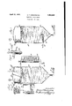
- WhlCll- Figure 1 is a diagrammatic view showing the apparatus in vertical section
- Fig. 2 is an enlarged partial vertical section of the spray nozzle shown in Fig. 1;
- Fig. 3 is a similar view of a reaction chamber similar to that of Fig. 1 showing a modified form of the spray device.
- a reaction chamber 10 is heated by means of a pipe coil 11 through which oil is circulated by means of a pump P, the oil 11 being heated in a well known manner by means of a suitable furnace 12.
- Fresh oil may be introduced into the system through a pipe 13.
- a suitable dephlegmator or the like 14 connects with the top of the reaction chamber above the normal level of the oil therein, and is controlled by means of a valve 15. Vapors, as gasoline or the like, passing the valve 15 are condensed in suitable condensing coils 16 which are cooled in a well known manner, the liquid as gasoline or the like being stored in a suitable tank 17. Residual oil is withdrawn preferably from the bottom of the reaction chamber 10 through a draw-off pipe 18 which is controlled by means of a valve 19.
- the temperature is sufiiciently high to cause the liquid solvent or ve hicle to become very quickly vaporized, thereb leaving the salt solid in the form of finely go into colloidal dispersion or suspension therein.
- the nozzle 20 is so situated as to preclude the possibility of spraying any of the liquid partlcles containing the salt directly against the walls of the reaction chamber 10.
- the stream of the liquid particles is so directed as to cause, the liquid to be vaporized before the particles can come in contact with a wall of the vessel.
- no deposition of the salt can be made upon the walls of the vessel, inasmuch as the salt or other solid being in colloidal suspension in the oil will not adhere to the walls of the vessel, as would be the case if the liquid solution were to be allowed to come in contact with the walls of the vessel before evaporation of the liquid solvent or carrier took place.
- Fig. 3 is shown a modification of the construction in which the reaction chamber 10a is supplied with the same kinds of salts or other solids for solution or suspension in liquid through a spray nozzle 24, which is located beneath the surface of the hydrocarbon oil to be treated and preferably near the bottom.
- This nozzle is preferably surrounded with a suitable heat insulating covering 25, the effect of which is to prevent evaporation, to a large extent at least, of the liquid solvent or vehicle.
- the nozzle 20 of Figs. 1 and 2 may also be provided with an insulating covering for the same reason;
- steam may be added, if desired, but the device will operate quite effectually if the nozzle is supplied only with a salt solution or with a solid in suspension in a liquid under suflicient pressure to cause it to be forced into the reaction chamber against the pressure therein, and also sufficient to prevent clogging of the nozzle due to the deposition of the solute or other solid which is carried thereby.
- This liquid solvent or carrier preferably asauua action chamber is treated, so that when this liquid material is injected into the reaction chamber through either the nozzle 20 or the nozzle 24, the liquid solvent or vehicle will rapidly be evaporated leaving the solid behind in the hydrocarbon oil.
- this liquid material is injected through the nozzle 24 the steam orvapor thus formed in the hot oil causes the solid particles, which are simultaneously formed, to be separated from each other in a finely divided state of colloidal dispersion in the hot oil.
- the steam or ve or of the liquid thus generated assists great y in removing the vapors-of gasoline and other light hydrocarbons from the oil through which they rise.
- the discrete solid particles thus dispersed throughout the body of oil under treatment act as nuclei for the deposition of carbon, and at the same time provide surfaces where cracking of the oil can readily occur, the deposition of carbon being an incident to the cracking of the oil.
- this carbon continues to be deposited upon these solid particles, it will no longer remain in suspension, unless agitated, but sinks and is drawn ofi from the body of the oil, either continuously or intermittently through the pipe 18, fresh cracking stock being supplied through the pipe 13 and fresh solid particles are supplied to the oil through the nozzles 20 or 24, so as to maintain the level of the oil substantially constant.
- the solution should be added sufiiciently far from the sides of the apparatus and commingled with the hydrocarbon therethe sprinklers 28, by means of a pump (not shown) which is disposed'between the pipes 33 and 34 which are respectively connected to the trough and the sprinklers.
- the water passes from the sprinklers down through the screens 29, bein cooled in its downward path, as in usual practice by the passage of air through the tower.
- the cooling water falls over the perforated distributin pan 31 and'is distributed over the tubes of changer tube unit 30, passing on to thecollecting trough 32, whereupon the cycle is repeated.
- Fig. 8 there is illustrated an application of the. heat exchanger tube unit of this in-' vention to a standard type of evaporator.
- the evaporator comprises an outer shell indicated generally by, the numeral 40, which shell is provided with inlet ports 41 and outlet port 42.
- the heat exchanger tube unit is horizontally disposedwithin the shell 40, an opening 43 being provided in one end of the shell through which the tube unit is inserted and removed.
- a flanged collar 44 is provided around the periphery of the opening 43.
- the head 46 comprises a dome shaped casting having a transverse wall 47 formed therein, dividing the'head'into relatively large and small respective upper and lower compartments.
- An inlet port 48 is provided in the upper compartment and an outlet port 49 is provided in the lower compartment.
- the head 46, tube sheet 45 and collar 44 are secured together by bolts not shown.
- a dome shapedhead' 50 is provided at the opposite end of the tube unit.
- the head'50 is formedwith a peripheral flange 51 and is secured to the tube sheet 52 by bolts not shown. A compartment is thus provided at this end of the unit into which all of the tubes open.
- Transverse beams 53 and 54 are provided for supporting the unit while permitting the same to slide longitudinally thereon.
- a port 55 having a suitable removable cover 56 is provided in the lower portion of the tank, as in usual practice, for removing deposits and affording access to the interior of the shell.
- heating fluid is introduced to the exchanger tube unit through the port 48 and passes through the tubes in substantially the same manner as described with reference to the former struceat ex-' the heating fluid while at its highest temperature wlll be passing through the tubes toward the head 50, and while at its lowest tem? perature'will be passing back toward. the head 46, and thus the fluid while at a high temperature will be passin through a greater number of tubes than vihile at a lowered one, thereby effecting the greatest possible heat exchange.
- Liquid to be vaporized is introduced into the shell through the inlet ports 41 where it circulates around the tubes 3, and vapor which is formed by the exchange of heat, passes out through the outlet'port 42.
- Bowing of the tubes for the purpose of removin deposit formed thereon may be effected either by introducing steam into the tubes, through the opening 48 or by simply varying the temperature of the heating fluid passed therethrough.
- a separate port similar to port 21, may be formed in the head 46 for separately introducing steam.
- a straight tube adapted for the circulation of fluid therethrough; and means for automatically effecting curvature of said tube when the same is elongated by the application of heat thereto.
- a normally straight tube adapted for the circulation of fluid therethrough; bending means adjacent said tube normally held in an angular position; means connecting said tubes and said bending means at the respective ends thereof; and means operatively connecting said tube with said bending means between said respective ends, whereby said bending means will be moved from angular position to straight line position and will eflect a curvature of said tubes when the same between said tubes and said bending means atthe respective ends thereof; and means op-' eratively connecting said tubes with said bending meansbetween the said respective ends,- whereby said bending. means will be moved from angular to straight line position and will effect a curvature of said tubes when elongation of said tubes is caused by the application of heat thereto.
- a heat exchanger the combination of a plurality of normally, straight tubes, adapted for the circulation of fluid therethrough; a tubeplate at each of the opposite ends of said tubes securing thesame in their relative positions; tie members secured to said tube plates said tie membersbeing normally held in angular positions; and'means disposed between the said tube plates. operatively connecting said tubes and said tie members, whereby upon elongation of said tubes caused by the application of heat thereto. said tube plates will be moved outwardly efiecting a straightening of said tie members and causing curvature of said tubes,.and whereby said tube lation,
- each fr'd t t.co"r" tb lt-,, 0 gm compar men q mp 15mg a u a e will be moved outwardly to efiect the straighton its innerend in which the ends of said tubes are secured, a substantially box shaped bodyportion, and a cover disposed over its outer end, tie members having ends secured in said compartments and normally held in angular positions; and means.
- a heat exchanger In a heat exchanger, the combination of a plurality of spaced, parallel, normally straight tubes'adapted for the circulation of fluid therethrough; a tube plate disposed at each ofthe opposite ends of said tubes securing the same in "their relative positions; a
- a-pluralit of spaced, parallel, normally straight tu es the combination of a-pluralit of spaced, parallel, normally straight tu es; tube plates disposed at the opposite ends ofsaid, tubes holding the same in their relative positions; a plurality of tie members connected to said tube plates and normally held in angular positions; and means disposed between said tube plates connecting said tie members with said tubes whereby upon elongation of said tubes b the application of heat thereto, said tube p ates relative spaced positions; tie members for each group-of tubes connected to the tube plates and normally held in angular positions; and means for each group of tubes operatively connecting its said guide member and said tie member, whereby upon elongationof said tubes by the application of heat thereto, said tube plates will be moved apart and said tie members will be moved to straight line positions and curvature of said tubes will be efi'ected thereby.
- a heat exchanger the combination of a plurality of groups of parallel, spaced, normally straight tubes; a tube plate disposed at each of the'opposite ends of said tubes, securing the same in their relative positions; a guide plate for the tubes of each of said groups, said guide plate havinga.
- a heat exchanger the combination of a plurality of spaced, parallel, normally straight tubes; substantially box shaped head members disposed at the opposite ends of said tubes having tube plates on their inner sides, said tube plates holding the ends of said tubes in their relative positions, and said head members having cover plates disposed on their outer sides, one of said head members having a transverse wall formed therein dividin the interior of same into two sections, an an inlet port formed in one section of said head member and an outlet port formed inv theother section, whereby a fluid may be circulated through said head members and 7 tubes; and tie members secured to said tube plates normally held in an angular position and operatively connected to the central portions of said tubes, whereby upon elongation of said tubes by the application of heat thereto, said head members will be moved apart and said tie members will be moved to straight line position effecting thecurvature of said tubes.
- a heat exchanger the combination of a plurality of spaced, parallel, normally straight tubes; substantially box shaped head members disposed at the opposite ends of said tubes, havlng tube plates secured on their inner sides, said tube plates holding the ends of the tubes in their relative positions, and said head members having cover lates disposed on their outer sides, one of sai headmembers having a transverse wall formed therein dividing the interior of same into two sections, and an inlet porttformed in one section of said head member and an outlet port .formed in the other section, whereby fluid may be circulated through said head members and tubes; and tie members secured to said tube plates normally held in an angular position and operatively connected-to the
Landscapes
- Chemical & Material Sciences (AREA)
- Oil, Petroleum & Natural Gas (AREA)
- Engineering & Computer Science (AREA)
- Chemical Kinetics & Catalysis (AREA)
- General Chemical & Material Sciences (AREA)
- Organic Chemistry (AREA)
- Heat-Exchange Devices With Radiators And Conduit Assemblies (AREA)
Description
.April 12, 1932. I H. T. DARLINGTON i" I m IIllI I I II Filed Nov. 24, 1926 Patented Apr. 12, 1932 UNITED A STATES PATENT OFFICE HOMER T. DAR-LINGTON, OF WEST CHESTER, PENNSYLVANIA, ASSIGNOR TO MARTIN B. SCHUSTER, TRUSTEE, OF JOLIET, ILLINOIS TREATING HYDROGARBON S Application filed November 24, 1926. Serial No. 150,630.
My invention relates to a method of treating liquid hydrocarbon for the purpose of promoting cracking and the production of the lighter distillates, particularly gasoline, or for the purpose of lightening the quality, and reducing the viscosity of the hydrocarbon, or for otherwise beneficially influencing and promoting the cracking operation in ways which will more fully appear from the following specification.
In carrying out the art of my invention, I
- bring together hydrocarbon and ordinary salt, alum, sodium-sulphate, aluminum-chloride (dissolved in water), or other chemical salts, or -any combination of one or more of them, in aqueous or other solution into hydrocarbon oil under conditions of temperature and pressure conducive to cracking oil, in such a manner that on evaporation of the solvent named above the agent is left as favorable colloid nuclei incorporated or dispersed, or both, in the hydrocarbon being treated, bringing about cracking and changes favorable for the elimination of carbon as a suspension in the residue oil. Favorable conditions for the carrying out of the present process are the following, to-wit: a temperature above 450 F., but preferably in practice between 750 F. and 1000 F., and a pressure sufficient to keep the hydrocarbons which are heavier than gasoline liquid at the temperature used, said pressures ordinarily running between 100 pounds and 1500 pounds to the square inch.
I find it favorable to emulsify. or homogenize the salt solution in oil and spray the emulsion into the hot chamber; for instance, into a gas space above the oil in a reaction chamber or a cracking still, or spray as above through gas into hot oil, or force it directly into the hot oil, preferably through an insulated nozzle, or to bring together hot oil from the cracking still with the oil emulsion, in which cases the evaporation of the solvent leaves the salts in a dispersed or incorporated form which for practical purposes is equivalent or nearly so to a colloidal dispersion or incorporation, though not necessarily chemically so, where, upon acting as an aid in cracking, the nuclei salts become coated with carbon and can be removed from the still continually or intermittently.
shown in the accompanying drawings, in WhlCll- Figure 1 is a diagrammatic view showing the apparatus in vertical section;
Fig. 2 is an enlarged partial vertical section of the spray nozzle shown in Fig. 1; and
Fig. 3 is a similar view of a reaction chamber similar to that of Fig. 1 showing a modified form of the spray device.
In the embodiment illustrated, a reaction chamber 10 is heated by means of a pipe coil 11 through which oil is circulated by means of a pump P, the oil 11 being heated in a well known manner by means of a suitable furnace 12. Fresh oil may be introduced into the system through a pipe 13. A suitable dephlegmator or the like 14 connects with the top of the reaction chamber above the normal level of the oil therein, and is controlled by means of a valve 15. Vapors, as gasoline or the like, passing the valve 15 are condensed in suitable condensing coils 16 which are cooled in a well known manner, the liquid as gasoline or the like being stored in a suitable tank 17. Residual oil is withdrawn preferably from the bottom of the reaction chamber 10 through a draw-off pipe 18 which is controlled by means of a valve 19.
The foregoing apparatus is well known in the oil cracking art. To this I have added a spray nozzle, which consists of an outer shell 20, to which is supplied through a pipe 21 a suitable salt solution or the like, as will hereinafter be described. For properly atomizing the liquid passing the nozzle 20, I have provided a steam pipe 22 with steam supplied thereto at a suitable pressure for prop- Apparatus for carrying out this process is against the surface of the liquid in the reacdivided particles which enter the oil and 4 tion chamber 10. Since this reaction cham:
her is maintained under conditions of temrature and superatmospheric pressure conucive to cracking, the temperature is sufiiciently high to cause the liquid solvent or ve hicle to become very quickly vaporized, thereb leaving the salt solid in the form of finely go into colloidal dispersion or suspension therein.
The nozzle 20 is so situated as to preclude the possibility of spraying any of the liquid partlcles containing the salt directly against the walls of the reaction chamber 10. In other words, the stream of the liquid particles is so directed as to cause, the liquid to be vaporized before the particles can come in contact with a wall of the vessel. In this way, no deposition of the salt can be made upon the walls of the vessel, inasmuch as the salt or other solid being in colloidal suspension in the oil will not adhere to the walls of the vessel, as would be the case if the liquid solution were to be allowed to come in contact with the walls of the vessel before evaporation of the liquid solvent or carrier took place.
In Fig. 3 is shown a modification of the construction in which the reaction chamber 10a is supplied with the same kinds of salts or other solids for solution or suspension in liquid through a spray nozzle 24, which is located beneath the surface of the hydrocarbon oil to be treated and preferably near the bottom. This nozzle is preferably surrounded with a suitable heat insulating covering 25, the effect of which is to prevent evaporation, to a large extent at least, of the liquid solvent or vehicle. If desired, the nozzle 20 of Figs. 1 and 2 may also be provided with an insulating covering for the same reason;
namely, to prevent the deposition of solids within the nozzle due to evaporation of the liquid solvent 'or vehicle.
In the form shown in Fig. 3 steam may be added, if desired, but the device will operate quite effectually if the nozzle is supplied only with a salt solution or with a solid in suspension in a liquid under suflicient pressure to cause it to be forced into the reaction chamber against the pressure therein, and also sufficient to prevent clogging of the nozzle due to the deposition of the solute or other solid which is carried thereby.
This liquid solvent or carrier preferably asauua action chamber is treated, so that when this liquid material is injected into the reaction chamber through either the nozzle 20 or the nozzle 24, the liquid solvent or vehicle will rapidly be evaporated leaving the solid behind in the hydrocarbon oil. When this liquid material is injected through the nozzle 24 the steam orvapor thus formed in the hot oil causes the solid particles, which are simultaneously formed, to be separated from each other in a finely divided state of colloidal dispersion in the hot oil. At the same time. the steam or ve or of the liquid thus generated assists great y in removing the vapors-of gasoline and other light hydrocarbons from the oil through which they rise.
The discrete solid particles thus dispersed throughout the body of oil under treatment act as nuclei for the deposition of carbon, and at the same time provide surfaces where cracking of the oil can readily occur, the deposition of carbon being an incident to the cracking of the oil. As this carbon continues to be deposited upon these solid particles, it will no longer remain in suspension, unless agitated, but sinks and is drawn ofi from the body of the oil, either continuously or intermittently through the pipe 18, fresh cracking stock being supplied through the pipe 13 and fresh solid particles are supplied to the oil through the nozzles 20 or 24, so as to maintain the level of the oil substantially constant.
I have found that when'salts are favorable to the production of cracking, deposition of carbon, decolorizing, or other purposes, I am enabled to get the maximum amount of efficiency by bringing them to the smallest size possible, and that by putting them in solution and treating them in the manner described, these particles do not again coalesce, but are held separate from each other and expose the largest possible surface for effective use to the desired end.
Attention is called to the fact that in the past, particularly in distillin oils containing salt water have brought a out expensive operating conditions, as the salt has crystallized on the sides of thestills, forming an objectionable coating. I obviate this trouble by bringing such oils containing natural salt or chemical salts in suspension or dispersion, directly into the presence of hot oil, and commingling and incorporating them therewith, at a temperature and pressure suflicient to almost immediately evaporate the water or other solvent, thus leaving the salt or salts in a dispersed or incorporated form, accomplishing by means of my discovery a favorable way of influencing the treatment of oils under conditions of heat and pressure conducive to cracking. The solution should be added sufiiciently far from the sides of the apparatus and commingled with the hydrocarbon therethe sprinklers 28, by means of a pump (not shown) which is disposed'between the pipes 33 and 34 which are respectively connected to the trough and the sprinklers. The water passes from the sprinklers down through the screens 29, bein cooled in its downward path, as in usual practice by the passage of air through the tower. The cooling water falls over the perforated distributin pan 31 and'is distributed over the tubes of changer tube unit 30, passing on to thecollecting trough 32, whereupon the cycle is repeated. In the cooling tower illustrated, four heat exchanger tube units are employed, the fluid to be cooled being circulated through the units and the bowing of the tubes for the purpose of removing deposits therefrom being eflected when desired, as described with reference to Figs. 1 to 5.
In Fig. 8 there is illustrated an application of the. heat exchanger tube unit of this in-' vention to a standard type of evaporator. The evaporator comprises an outer shell indicated generally by, the numeral 40, which shell is provided with inlet ports 41 and outlet port 42. The heat exchanger tube unit is horizontally disposedwithin the shell 40, an opening 43 being provided in one end of the shell through which the tube unit is inserted and removed. A flanged collar 44 is provided around the periphery of the opening 43. The periphery of the tube sheet 45 at the,
outer end of the tube unit, is adjacent the flanged collar 44. In this construction of the tube unit, modified forms of heads are employed. The head 46 comprises a dome shaped casting having a transverse wall 47 formed therein, dividing the'head'into relatively large and small respective upper and lower compartments. An inlet port 48 is provided in the upper compartment and an outlet port 49 is provided in the lower compartment. The head 46, tube sheet 45 and collar 44 are secured together by bolts not shown. At the opposite end of the tube unit a dome shapedhead' 50 is provided. The head'50 is formedwith a peripheral flange 51 and is secured to the tube sheet 52 by bolts not shown. A compartment is thus provided at this end of the unit into which all of the tubes open. This end of the unit is free for longitudinal motion as the tubes expandor contract. Transverse beams 53 and 54 are provided for supporting the unit while permitting the same to slide longitudinally thereon. A port 55 having a suitable removable cover 56 is provided in the lower portion of the tank, as in usual practice, for removing deposits and affording access to the interior of the shell.
In the operation of the vaporizer, heating fluid is introduced to the exchanger tube unit through the port 48 and passes through the tubes in substantially the same manner as described with reference to the former struceat ex-' the heating fluid while at its highest temperature wlll be passing through the tubes toward the head 50, and while at its lowest tem? perature'will be passing back toward. the head 46, and thus the fluid while at a high temperature will be passin through a greater number of tubes than vihile at a lowered one, thereby effecting the greatest possible heat exchange. Liquid to be vaporized is introduced into the shell through the inlet ports 41 where it circulates around the tubes 3, and vapor which is formed by the exchange of heat, passes out through the outlet'port 42. Bowing of the tubes for the purpose of removin deposit formed thereon may be effected either by introducing steam into the tubes, through the opening 48 or by simply varying the temperature of the heating fluid passed therethrough. When desired a separate port, similar to port 21, may be formed in the head 46 for separately introducing steam.
While there. has been hereinbefore described specific embodimentsof the instant invention it will be understood that many and various changes and modifications in form, procedure, details of construction and ap lications of the invention may be made w1th-- o'ut departing from the spirit of the invention, and it will be'understood that all and any such changes and modifications as fall within the scope of the appended claims are contemplated and are to be considered as a part of the instant invention. L
What we claim as new and desire to secure by Letters Patent is: i
1. In a heat exchanger, the combination of a straight tube, adapted for the circulation of fluid therethrough; and means for automatically effecting curvature of said tube when the same is elongated by the application of heat thereto.
2. In a heat exchanger, the combination of a plurality of straight, parallel, spaced tubes, adapted for the circulation of fluid therethrough; and means operatively connected to said tubes for automatically effecting curvature of the same when said tubes are elongated by the application of heat thereto. 3. In a heat exchanger, the combination of a normally straight tube adapted for the circulation of fluid therethrough; bending means adjacent said tube normally held in an angular position; means connecting said tubes and said bending means at the respective ends thereof; and means operatively connecting said tube with said bending means between said respective ends, whereby said bending means will be moved from angular position to straight line position and will eflect a curvature of said tubes when the same between said tubes and said bending means atthe respective ends thereof; and means op-' eratively connecting said tubes with said bending meansbetween the said respective ends,- whereby said bending. means will be moved from angular to straight line position and will effect a curvature of said tubes when elongation of said tubes is caused by the application of heat thereto.
5. In a heat exchanger, the combination of a plurality of normally, straight tubes, adapted for the circulation of fluid therethrough; a tubeplate at each of the opposite ends of said tubes securing thesame in their relative positions; tie members secured to said tube plates said tie membersbeing normally held in angular positions; and'means disposed between the said tube plates. operatively connecting said tubes and said tie members, whereby upon elongation of said tubes caused by the application of heat thereto. said tube plates will be moved outwardly efiecting a straightening of said tie members and causing curvature of said tubes,.and whereby said tube lation,
plates willbe heldin fixed spaced relation when said-tie members have reached straight line positions and further elongation of said tubes will effect further curvature of the same while their ends are held in fixed spaced re- '6. In a, heat exchanger, the combination of a plurality of spaced. parallel, normally straight tubes; compartments disposed at the opposite ends of said tubes,adapting the same for the circulation of fluid therethrough, each fr'd t t.co"r" tb lt-,, 0 gm compar men q mp 15mg a u a e =will be moved outwardly to efiect the straighton its innerend in which the ends of said tubes are secured, a substantially box shaped bodyportion, and a cover disposed over its outer end, tie members having ends secured in said compartments and normally held in angular positions; and means. disposed betweenthe tube plates, operatively connecting the tubes and tie members, whereby upon elongation of said tubes, caused by the application of heat thereto, said tube'plates will be moved outwardly to effect they straightening of said tie members from their angular -posi-.
tions and curvature of said tubes will be effected.
7 In a heat exchanger, the combination of a plurality of spaced, parallel, normally straight tubes'adapted for the circulation of fluid therethrough; a tube plate disposed at each ofthe opposite ends of said tubes securing the same in "their relative positions; a
angular: positions and guide plate disposedbetween said tube plates I O straightening of said tie' members from their curvature of said tubes In 'a'heat 'exchanger, the combination of a-normally straight tube adapted for the circulation- -offluidtherethrough; tying means adj accentv said tube normally held in an connecting means will-be moved apart and said angular tying means will be moved to a straight line position effecting a curvature of said tubes. v
9. In a heat exchanger, the combination of a-pluralit of spaced, parallel, normally straight tu es; tube plates disposed at the opposite ends ofsaid, tubes holding the same in their relative positions; a plurality of tie members connected to said tube plates and normally held in angular positions; and means disposed between said tube plates connecting said tie members with said tubes whereby upon elongation of said tubes b the application of heat thereto, said tube p ates relative spaced positions; tie members for each group-of tubes connected to the tube plates and normally held in angular positions; and means for each group of tubes operatively connecting its said guide member and said tie member, whereby upon elongationof said tubes by the application of heat thereto, said tube plates will be moved apart and said tie members will be moved to straight line positions and curvature of said tubes will be efi'ected thereby.
11. In a heat exchanger, the combination of a plurality of groups of parallel, spaced, normally straight tubes; a tube plate disposed at each of the'opposite ends of said tubes, securing the same in their relative positions; a guide plate for the tubes of each of said groups, said guide plate havinga. plurality of orifices formed therein through which said tubes are passed; tie members for each group of tubes connected with said tube plates, said tie members having hinged concentral portions of said tubes, whereby upon elongatlon of said tubes, by the application of heat thereto, said head members will be moved apart and said tie members will be moved to straight line position efiecting the curvature of said tubes, and said divided head member havin a steam port formed therein for the intro notion of steam into the same.-
GEORGE T. JACOCKS.
JOHN L. KRIEG.
nections adjacent said guide plates and being normally held in angular positions; and means on said guide plates operatively connecting the same to the tie members of their respective groups, whereby upon elongation of said tubes by the application of heat thereto, said tube plates will be outwardly moved and said tie members will be moved to straight line positions, effecting the curvature of said tubes.
12. In a heat exchanger, the combination of a plurality of spaced, parallel, normally straight tubes; substantially box shaped head members disposed at the opposite ends of said tubes having tube plates on their inner sides, said tube plates holding the ends of said tubes in their relative positions, and said head members having cover plates disposed on their outer sides, one of said head members having a transverse wall formed therein dividin the interior of same into two sections, an an inlet port formed in one section of said head member and an outlet port formed inv theother section, whereby a fluid may be circulated through said head members and 7 tubes; and tie members secured to said tube plates normally held in an angular position and operatively connected to the central portions of said tubes, whereby upon elongation of said tubes by the application of heat thereto, said head members will be moved apart and said tie members will be moved to straight line position effecting thecurvature of said tubes.
13. In a heat exchanger, the combination of a plurality of spaced, parallel, normally straight tubes; substantially box shaped head members disposed at the opposite ends of said tubes, havlng tube plates secured on their inner sides, said tube plates holding the ends of the tubes in their relative positions, and said head members having cover lates disposed on their outer sides, one of sai headmembers having a transverse wall formed therein dividing the interior of same into two sections, and an inlet porttformed in one section of said head member and an outlet port .formed in the other section, whereby fluid may be circulated through said head members and tubes; and tie members secured to said tube plates normally held in an angular position and operatively connected-to the
Priority Applications (1)
| Application Number | Priority Date | Filing Date | Title |
|---|---|---|---|
| US150630A US1853552A (en) | 1926-11-24 | 1926-11-24 | Treating hydrocarbons |
Applications Claiming Priority (1)
| Application Number | Priority Date | Filing Date | Title |
|---|---|---|---|
| US150630A US1853552A (en) | 1926-11-24 | 1926-11-24 | Treating hydrocarbons |
Publications (1)
| Publication Number | Publication Date |
|---|---|
| US1853552A true US1853552A (en) | 1932-04-12 |
Family
ID=22535367
Family Applications (1)
| Application Number | Title | Priority Date | Filing Date |
|---|---|---|---|
| US150630A Expired - Lifetime US1853552A (en) | 1926-11-24 | 1926-11-24 | Treating hydrocarbons |
Country Status (1)
| Country | Link |
|---|---|
| US (1) | US1853552A (en) |
Cited By (2)
| Publication number | Priority date | Publication date | Assignee | Title |
|---|---|---|---|---|
| US2938852A (en) * | 1956-09-20 | 1960-05-31 | Standard Oil Co | Coking process |
| US3133014A (en) * | 1960-12-30 | 1964-05-12 | Air Prod & Chem | Quench system for synthetic crude |
-
1926
- 1926-11-24 US US150630A patent/US1853552A/en not_active Expired - Lifetime
Cited By (2)
| Publication number | Priority date | Publication date | Assignee | Title |
|---|---|---|---|---|
| US2938852A (en) * | 1956-09-20 | 1960-05-31 | Standard Oil Co | Coking process |
| US3133014A (en) * | 1960-12-30 | 1964-05-12 | Air Prod & Chem | Quench system for synthetic crude |
Similar Documents
| Publication | Publication Date | Title |
|---|---|---|
| US2805981A (en) | Process and apparatus for flash distillation | |
| US1853552A (en) | Treating hydrocarbons | |
| US2868714A (en) | Apparatus and method for flash evaporating oils | |
| US1836004A (en) | Apparatus for treating gas | |
| US1972948A (en) | Hydrogenation of oils | |
| US2093588A (en) | Process of cracking heavy hydrocarbon oils | |
| US1616209A (en) | Method of and means for treating oils | |
| US2479267A (en) | Apparatus for promoting recirculation and reducing ebullition and priming in evaporators | |
| US2204062A (en) | Water deaerator and purifier | |
| US1427626A (en) | Ernest v | |
| US1868462A (en) | Process for producing oil gas | |
| US1766863A (en) | Separating substances of dissimilar volatilities | |
| US2332215A (en) | Distillation apparatus | |
| US1885716A (en) | Oil converter | |
| US1656710A (en) | Refining oils | |
| US1664977A (en) | Art of distilling lubricating oils | |
| US1781872A (en) | Process for making motor fuel | |
| US1456419A (en) | Process and apparatus for the production of low boiling point hydrocarbons | |
| US2404677A (en) | Fractional distillation | |
| US1262875A (en) | Process of treating petroleum. | |
| US1916205A (en) | Apparatus for converting petroleum hydrocarbons | |
| US1420832A (en) | Process for cracking oils | |
| US1462678A (en) | Oil-converting apparatus | |
| US1774228A (en) | Process for cracking hydrocarbon oil | |
| US1220504A (en) | Apparatus for dehydrating hydrocarbon-oils. |