US2332215A - Distillation apparatus - Google Patents
Distillation apparatus Download PDFInfo
- Publication number
- US2332215A US2332215A US414993A US41499341A US2332215A US 2332215 A US2332215 A US 2332215A US 414993 A US414993 A US 414993A US 41499341 A US41499341 A US 41499341A US 2332215 A US2332215 A US 2332215A
- Authority
- US
- United States
- Prior art keywords
- vapors
- still
- scrubber
- liquid
- line
- Prior art date
- Legal status (The legal status is an assumption and is not a legal conclusion. Google has not performed a legal analysis and makes no representation as to the accuracy of the status listed.)
- Expired - Lifetime
Links
Images


Classifications
-
- B—PERFORMING OPERATIONS; TRANSPORTING
- B01—PHYSICAL OR CHEMICAL PROCESSES OR APPARATUS IN GENERAL
- B01D—SEPARATION
- B01D1/00—Evaporating
- B01D1/16—Evaporating by spraying
Definitions
- the preheated liquid or solution then is spray vaporized or atomized Within a still maintained at a temperature at which, under the pressure conditions existing therein, the liquid is quickly vaporized.
- the resultant vapors promptly thereafter pass into intimate contact with a mass of inert contact material maintained at approximtely the temperature of the still, the said contact material preferably consisting of a mineral wool or glass wool so loosely packed that it offers little or no resistance to the passage therethrough of the vapors.
- the liquid particles in the vapors or mist are deposited or coalesce upon the surfaces of this inert material, while the true vapors freely pass therethrough.
- the arrangement of parts preferably is such that the fluids fiow downwardly through the scrubber material.
- the scrubber or immediately upon leaving the latter, the vapors change direction sharply, while still being maintained at substantially their distillation temperature, whereby any coalesced liquid particle still present therein are thrown out.
- the vapors then flow quickly from the still to the first of a series of condensers. In each of the latter the vapors flow downwardly,diiferent fractions thereof being condensed in the respective condensers depending upon the conditions maintained therein, and upon the nature of the vapors beingcondensed, and are withdrawn from the bottomof the condenser in which condensed.
- means are provided for maintaining the still and condenser system under high vacuum to facilitate operation of the still-scrubber unit at a temperature at which, during the extremely short period of existence of the vapors at'such temperatures, no decomposition of the heat-sensitive materials occur, even in the. presence ofthe highly heated contact materials mentioned.
- means are provided forintroducingan inertgas such as carbon dioxide, nitrogen, natural, gas, methane or hydrogen into the. still with the atomized solution in order. to facilitate the distillation of the solution at temperatures suificiently low to prevent decomposition of the organic compounds.
- the advantage :of this partial pressure r effect may be secured in operations conducted under atmospheric pressure as well as under .vacuum. a
- a petroleum oil to be refined such as in crude petroleum or a used lubricating grade of hydrocarbon oil, preferably after filtration or othertreatment to remove insoluble material, is preheated to an elevated temperature below that at which decomposition occurs, and preferably below about 570 F.
- the preheated oil then is spray-atomized into a still within a flowing stream of a suitable highly heated gas which is substantially inert or resistant to decomposition at the oil distillation temperature, such as methane, natural gas or'nitrogen.
- the inert gas is at a temperature which may be sufficiently high to superheat the preheated oil entering the still.
- the still may be under approximatelyatmospheric pressure, and at a temperature at which theoil is quickly vaporized Within the body of hot inert gas.
- the resultant vapors promptly contact a coalescing and stripping means hereinafter described which is maintained at ap roximately the distillation tempera- .ture of the oil.' Unvaporized oil particles are Within coalesced and separated from the mixed vapors and gases under conditions whereby countercurrent flow of the stripped vapors and the coalesced material is prevented.
- the stripped vapors then flow through a series of condensers such as hereinafter described and are fractionally condensed, the lubricating fractions being separately recovered.
- the uncondensed carrier and heating gas is withdrawn from the last condenser, and is reheated and recycled to the still under a selected uniform pressure and flow rate.
- the centrifugal type of scrubbing means shown in Fig. 5 of the accompanying drawings preferably is used when distilling hydrocarbon oils or other liquids at pressures around atmospheric or above, using circulating heating and carrier gas.
- coalescence of the liquid and solid particles present in the spray or mist delivered within the still be efiectedpromptly after the spraying operation by suitable means, such as a contact mass which itself is at a temperature substantially that of the mixed vapors, so that such coalescenceis accomplished while condensationof all vapors is prevented.
- suitable means such as a contact mass which itself is at a temperature substantially that of the mixed vapors, so that such coalescenceis accomplished while condensationof all vapors is prevented.
- the contact mass in the scrubber shouldbe so arranged as to offer substantially little or no resistance to the downward flow of the vapors therethrough.
- the subsequent sharp change of direction of therapidly flowing vapors assists to separate therefrom any traces of liquids and solids coalesced in the scrubher or dripping from the latter. No true filtering action is manifested.
- the solution of rosin and oily substances may be then treated in the cold with strong sulphuric acid to remove objectionable unsaturated compounds in wellknown manner, following which the residual acid and Water soluble reaction products are Washed from the solution of rosin with water. The solution is then filtered in the cold to remove precipitated matter or nigger therein.
- the filtered solution is then heated by suitable means to a'temperature suificiently high to vaporize the volatile constituents at the pressure existing in the distillation zone, but below the temperature at which substantial cracking and decomposition of the volatilized components can occur under the conditions of operation.
- suitable means to a'temperature suificiently high to vaporize the volatile constituents at the pressure existing in the distillation zone, but below the temperature at which substantial cracking and decomposition of the volatilized components can occur under the conditions of operation.
- the solution is preheated to a temperature below around 315 C., and prefseal with the flanged margins 31 of the still wall and with an interposed gasket of suitable material, these parts being secured together by bolts or their equivent.
- a closure plate 41 having a central opening and carrying an outlet conduit 49 in alignment with conduit 43 also is secured to the plate 46 and still 3
- Conduit- 49 has a lateral member I extending through the wall of the furnace housing.
- the front end of the furnace has a stack 53 for Waste furnace gases.
- the rear end of the housing is provided at the top with an insulated, removable capor cover 55 adapted to house the upper end of the still, scrubber and associated parts. The cover 55 is removed whenever the scrubber is taken out for inspection or treatment of the contact material.
- a series of condensers 51, 59, BI, 62 and 63 so arranged and constructed that the vapors to be condensed flow downwardly in each successive condenser. Liquids condensed in the respective condensers flow from the. lower outlets thereof into corresponding receivers .65,
- Each of said receivers is connected with a vacuum pump 55 through the conduit 81 and branch-controlled conduits asshown, and each has a valve-controlled liquid discharge line 88.
- Vapor conduits 89 connect the lower portion of each condenser with the upper portion of the next successive condenser.
- , 92 from the last receivers H, 8I lead to a vacuum pump (not shown) past valve 93, and conduct uncondensed gases from the system.
- valve 93 is closed, and a gas circulating pump 94 conducts the said gases to the spray nozzle in the still, from lines 9
- the line 98 passes through the furnace where the recirculated gases are again heated; and the line conducts the heated gases to the still and discharges them into the latter through an annular passage IElI surrounding the nozzle 35.
- a vessel 95 having an inlet line 97 for'the crude material and solvent, and a bottom outlet line having a valve-controlled waste discharge line 99, and a solution discharge line connected with a second vessel I03 by a valve-controlled conduit I94 having therein a pump I95.
- a liquid outlet line ill! from vessel I03 has therein a valve-controlled waste discharge line I99 and a pump III.
- Line IGl is connected with the upper inlet end of condenser 63, the construction of the latter being such that the liquid from line IIl'I flows downwardly and then upwardly through the tubes therein in indirect heat-exchange relation with the vapors flowing through the condenser from the still.
- the thus-heated liquid then flows successively through the lin s M3 to the other condensers of the series, and finally flows from condenser 51 through line II5 to the preheater 29.
- a valve-controlled line II! leads liquid from the preheater to the liquid inlet-line 33 at the still.
- Valve-controlled bypass line H6 permits bypassing of any condenser by any part or all of the liquid, when desired.
- a valve-controlled branch line II 9 connects the line II 5 directly with the inlet line 33 and permits bypassing the preheater by any or all of the liquid, where this is advantageous.
- the spray nozzle 35 is adapted to in troduce the liquid into the still in finely divided form under any selected pressure.
- a drain line I23 "connects the bottom of, the'still with a receiver I24 and auxiliary receiver I25,- each of the latter being connected with the vacuum line 81 as shown.
- a conduit I 21 connects the scrubber bottom with the drain line I23.
- a baflie I28 in the housing near the upper portion of the still directs the hot furnace gases around the rear end of, the still and scrubber to maintain .the sameat uniformly high temperatures.
- the dampers I5,- I1 the hot gases may be directed as desired over the pre heater and/or over either or both of the respective ends of the still.
- the scrubber 38-ma-y. function as a filter for removing any filterable material prescut, that is not its primary purpose.
- the usual finely divided filtering materials such as fullers earth, kaolin, absorbent clays, and the like, tend to obstruct the rapid flow cf vapors through and out of the high temperature scrub.- bing zone wherein unvaporized particles are 00- alesced. This is due to the relatively low percentage of voids present therein, as distinguished from glass wool, steel wool, glass beads, pieces of earthenware and the like employed by applicant as coalescing media.
- solid scrubbing medium having a high percentage of voids and similar terms refer to coalescing media of the latter type, which allows free flow of the vapors through and from the hot scrubbing zone.
- solid scrubbing medium having a high percentage of voids and similar terms refer to coalescing media of the latter type, which allows free flow of the vapors through and from the hot scrubbing zone.
- the heat-sensitive organic materials to be distilled are introduced into the vessel together with the desiredamount of the solvent, which is thoroughly mixed therewith.
- the solution then is treated with around 2 to 6% of concentrated sulphuric acid in wellknown manner in order to remove objectionable unsaturated bodies.
- the mixture in vessel 95 is settled, and the water and sludge are withdrawn through line 99.
- the residual liquid in the vessel is then washed with water, the washings also being removed through line99.
- the washed solution is then pumped into storage tank I03. From there it is pumped by pump III to the preheater 29, passing successively through each of the condensers 63, 62, 6!, 59, and 51.
- any or all of the condensers may be bypassed, if desired, through lines I Hi.
- the preheated solution flows from the preheater to the spray nozzle 35 through line II'I controlled by valve I30.
- the valve-controlled bypass line II9 permits the cooling or dilution when desired of the preheated solution flowing to the still.
- the vapors and atomized liquid particles formed in the still are quickly drawn into the hot scrubber .through its open upper end, and thence pass downwardly through the contact material to the scrubber bottom where the vapors abruptly change direction. Any coalesced liquids impinge or are deposited upon the said bottom, the hot stripped vapors being rapidly withdrawn from the scrubber through lines 43, 49, and M.
- the vacuum pump 85 serves to vacuumize the receivers and the residue storage tanks I24I25 after the latter have been cut ofi the line for discharge of their contents,
- Figs. 2 and 3 show another type of still, similar in general to that of Fig. l, but in which the still and scrubber are square in transverse cross-section.
- thescrubber I3! is in the rear end section of the still, and
- the latter is formed by the side walls I and rear end wall I36 of thestill, and a front wall or baflle member I38 which makes a fluid-tight joint with the still bottom and which extends upwardly to a point spaced from the still top so as to permit free access of vapors in the still to the upper end of the scrubber;
- the latter is separated into'an inlet or contact compartment and an outlet compartment by the outlet line I39 having a flanged lower end cooperating with a flange in the inner wall of the scrubber tosupport a screen or screens I40 carrying a body of mineral wool or other mist-coalescing solids, I4I.
- Supporting members I42 secured to the still wall and to line I39 reinforce the screens.
- Liquid drain lines I44, I45 respectively connect the still and scrubber with receiver I 24.
- the scrubber section of the still is removable from the furnace, being slideable on tracks I46, through a removable rear wall section I41 of the furnace housing.
- Figs. 4 to 6 illustrate a vform'of the invention that is especially adapted for use in operations conducted at or around atmospheric pressure, and where inert gases are introduced into the still to facilitate operations at low temperatures obviating decomposition of the material being distilled.
- a scrubber I is mounted wholly within the furnace housing 'II.
- the scrubber communicates with the outlet end of the still I5I through conduit I52, which extends within the scrubber and has its discharge end centrally disposed therein and directed upwardly.
- the scrubber has a vapor outlet I54 in the upper end.
- Liquid drain lines I55, I51, lead respectively from the bottoms of the crubber'and still to a suitable container, such as the receiver I24 (Fig.
- the side walls of the scrubber I50 slope outwardly in a downward direction, so that any liquid particles impinging thereon freely flow to the drain line.
- an electric motor I58 mounted upon the furnace housing is an electric motor I58, the armature shaft of which has anextension I60 extending through bearings carried by suitable bushings I62, I64, carried in thefurnace wall and'in the top of the scrubber.
- the extension also is provided with a central bearing carried by a centering spider I66 secured to the scrubber wall.
- a hollow cylindrical baffle number I68 having animperforate top and a central opening in its bottom to accommodate the conduit I52, is secured to the lower end of shaft I60 for rotation with the latter.
- the side walls of the number I68 are foraminous, and have secured thereto vertically disposed angle members I'IIladapted during rotation of the number I58 to impact the vapors and mist entering fromconduit I52 and to discharge them laterally'at high velocity against the walls of the rotatingmember I68 and of the scrubber I56.
- the other parts of the furnace and associated parts are in general the same as shown in Fig. 1.
- the centrifugal action of the rapidly rotating member I68 causes the vapors and suspended liquid particles to impinge upon'the' heated .walls of the scrubber where any liquid particles coalesce, and the resultant liquid stream flows to the drain line I56 and is removed.
- the stripped vapors thus freed from liquids and while still at high temperatures are rapidly withdrawn and flow to the first condenser of the series hereinbefore described.
- Figs. '1 and 8 illustrate stillv another form of distillation apparatus having-the scrubber or its equivalent'in the high-temperature distillation zone.
- the hot vapors leaving the atomiz-v ing nozzle 35 of the still enter the scrubber chamber I'lBthrough the spiral conduit IBM.
- the latter is disposed longitudinally of the scrubber and discharges fluids downwardly to a bottom outlet I82 spaced from thev bottom of the scrubber chamber, the hot vapors and suspended liquid particles beingsubjected to a centrifugal action as they flow downwardly to the bottom outlet I82, from-thence they rise upwardly outside of the conduit Iilil'under action of the main vacuum pump oonnected with the last condenser 63 (see Fig.
- Figs. 9 and 10 illustrate another type of stillscrubber assembly.
- the still 203] is mounted vertically upon checker work 2M within the furnace housing 202.
- the latter is heat-insulated and is provided with an auxiliary combustion chamber 254 having one or more burners 206, and a bafiie 201 to prevent direct flames from striking thebottom of the still.
- the flue gases leave the furnace through stack 258- having the damper 2G9.
- inlet end of the coil is connected with line I I5 (see outlet end is connected with the 35.
- the latter is wardly to discharge highly heated vapors and mist towards the bottom of the still.
- a vapor outlet member2I4 of gen- Fig. 1 Supported upon the sloping bottom of the still by members 2I2 and disposed vertically within and axially of the till-is a vapor outlet member2I4 of gen- Fig. 1), and the atomizing nozzle erally frusto-conicalshape, spaced from the side removed from thehighdirected downwalls of the still.
- ..An outlet line H6 is connected with the outlet of member 2 for conducting vapors therefrom to the series of condensers described in connection with Fig. 1.
- the lower margin of member 2M has a flange cooperating with a similar flange on inner wall of still 200 to support screens 2I5 that support a bed of solid contact or scrubbing material of the kind heretofore described.
- ! connect the said supporting flanges.
- the rate of flow of the atomized material within the still increases during its flow through the contact material. This, together with the abrupt change of direction of the vapors leaving the scrubber, and the slight reduction in their rate of flow at this point in their path, facilitate complete removal therefrom of all liquid components that otherwise would impart undesirable color to the condensate subsequently produced from the vapors.
- ! in the side wall of the still permits'inspection of the inside of still and scrubber, and the treatment or removal of the scrubber material when desired.
- Figs. 11 to 15 illustrate forms of the invention involving the employment of a relatively thin lining of corrosion-resistant metal for all parts coming in contact with hot fluids capable of corroding the usual ferrous metals.
- those apparatus elements exposed to high temperatures such as those around 260 C. or above, are constructed entirelyof corrosion-resistant metals or alloys such as nickel, stainless steel of the 18% Ni 8% Cr type, or Monel metal, while the elements exposed to lower temperatures, such as the condensers, pipes carrying cool liquids, etc., maybe made of these metals or of aluminum.
- the cost of the large quantity of these metals required for apparatus constructed ontirely therefrom is very great.
- Applicant also has made the surprising discovery that it is possible to obtain the desired M corrosion-resistance and long life for this type of apparatus made of the ordinary grades of steel and like ferrous metals and alloys and designed to be exposed to corrosive fluids, by securing upon the exposed surfaces of the apparatus a thin sheet lining of the said corrosionresistant metal having unwelded, uncaulked joints.
- the lining may be secured to the adjacent walls of the element being lined therewith by any suitable means, such as by spot-welding,
- this lining definitely prevents the corrosive fluids from reaching the corrodible metal walls of thevessel so lined.
- Fig. ll illustrates, a still-scrubber assembly having inner linings of the type described.
- all parts coming in contact with hot vapors are lined or covered with sheets of corrosicn-resistant metal secured in place in the manner indicated.
- Such parts include the still, scrubber, vapor outlet conduits 43, 49 and Si, and the respective supporting members 240 and 233 for the scrubber and the screen 45.
- a lapped joint in the metal lining is indicated at 230 in Fig. 11, and on a somewhat larger scale in Figs. 13 and 15.
- the open-topped scrubber 39 is supported upon the cover plate 43 by the spaced vertical angle members 240.
- Fig.1 14 shows a fragment of a still wall having suitably secured thereto a flange member 232.
- a lining sheet 234 of corrosion-resistant metal covers the inner wall surface and the flange 232. The lining is secured to the said flange by spaced spot welds 236. Both inner and outer surfaces of the scrubber and of the vapor conduit 43 are thus lined.
- the distillation apparatus of the invention essentially includes an assembly of heated units, comprising a preheater, a spray vaporizing still, a contact separator or scrubber, and a vapor outlet conduit, all disposed within a unitary heat-insulated furnace housing that is provided with means for producing and distributing a high temperature heating medium to selected parts of the said assembly.
- the scrubber is removably mounted Within the furnace housing-and can be withdrawn or reached for replacing or cleaning the contact material.
- the top part of the housing can beremoved, whereupon the scrubber can be disconnected from the still and removed overhead.
- the still of Fig. 9 is provided with a removable closure in its side wall for use in cleaning or replacing the contact material.
- the process features of the invention essentially comprise spray-vaporizing or atomizing a solution of a heat-sensitive organic material within a hot zone maintained at a temperature approximately as high or higher than that which the said solution possesses immediately prior to its atomization.
- the vapor mixture thus formed is quickly drawn from the still after passing through a scrubber or contact mass which oifers little or no resistance to they passage of the true vapors but which causes coalescence of finelydivided liquid or solid particles, thereby forming aggregates of. a size and weight sufficient to render them quickly and easily removable from the hot vapor stream when the latter is forced to change its direction suddenly while at the said highxtemperature.
- the coalesced liquid isremoved from .the vapor stream .withlthe assistance of gravity or of regulated'ceiitrifugal forceiap'plied adja- 'cent the vapor outlet from the still.
- the purer and'freer from.'col'or"bodies and other impurities will bethedistillates subsequently formed.
- A'countercurrentliquid-vapor contact device suchas a .de'phlgmating column is unsuitable for the treatment, of the hot vapors vwhere highly pure distillatea'ar desired;
- "The [requisite high speed of atomized vapors through andfromthehigh temperature'zone of the still Scrubber "assembly prf repiy is: effected 'under highvacuum-or by the use-ofa' rapidly recirculated strearnpf inert gas This" high speed flow fl'irtl'ierlisfacilitatedliy passlng tne'vapors downward through each of the condhsers and removing condensate therjefroi'nihthe direction of the .fiowof the vapors.
- I i I Ihefn'ov'el method he'reindscribed for apply.-
- Distillation apparatus comprising a heating chamber; a distillation vessel disposed within said chamber and having a vapor outlet; means for spray-atomizlng within said vessel a fluid to be distilled, means for withdrawing distilled vapors from said vessel through said outlet; and means operatively associated with said vessel and interposed between the said atomizlng means and said vapor outlet and completely housed within said heating chamber and adapted to coalesce and strip from the high temperature tohereiinedis limited,
- Distillation apparatus comprising a furnace having a preheating chamber and a main heating chamber; means for controlling the direction of heat flow within the main heating chamber; a
- distillation vessel disposed in the main heating chamber; spray-atomizing means inone end of the said distillation vessel; means operatively associated with the said vessel and completely housed within the said furnace and adapted to coalesce and'strip from the vapors leaving the said atomizlng means unvaporized' liquid and solid components while preventing 'countercu-rrent contact of the vapors and unvaporized components stripped therefrom; and means for withdrawing stripped vapors from the distillation vessel.
- Apparatus as defined in claims including a series'ofconden'sers connected with said distillation- "vessel and said coalescing and stripping meansjsna means for circulating a stream of inert gas-'throughthe distillation vessel, stripping means and series-of condensers.
- Apparatus as defined in claim 4 whereinth'e coalescing and stripping means comprises a body and inert inorganic material having a high per- -centage of voids andoli ering vapor flow therethrough.
- Apparatus as defined in claim 4 including a "series of condensers connected with the outlet f om said still and said coalescing and stripping mean and-magmas circulating a stream of inert gas through the distillation vessel, coalescing -an'd'strippin'g means and series of conden the said coalescing and stripping means comprising a centrifugal "liquid-vapor separator,
- Apparatus for distilling high-boiling heatsensitive liquids comprising, respectively within a heat-insulated furnace housing, a preheater, an atomizlng chamber, means for heating the said heat-insulated furnace housing, and means for coalescing and stripping from vapors leaving the said atomizlng chamber entrained liquids and solids in suspension therein while preventing countercurrent contact of the stripped vapors and the coalesced liquids and solids.
- the said coalescing and stripping means comprises a chamber mounted in the said atomizing chamber and having an inlet adapted to direct incoming vapors downwardly, means in the lower portion of the said coalescing and stripping the said housing and having a vapor inlet in permanent communication witlrthe said still and adapted to discharge vapors within the said unit;
- a distillation chamber housed within said furnace; means for atomizing the preheated oil .within said chamber; means for maintaining said .chamber at a temperature approximating that of the preheated oil; means for regulating the vapor pressure of the said oil within said chamber; means within the furnace for quickly coalescing and removing from the resultant vapor stream non-vaporized liquid and solid components present therein and for maintaining the stripped vapors at the said high temperature,
- .thelast-named means not materially retarding .the rate of flow of the vapors within the said chamber; means for quickly removing the stripped vapors from said chamber; and means for separately condensing from the stripped vapors a lubricating fraction of the oil thus refined.
- Distillation apparatus comprising a furnace having a preheating chamber and a main heating chamber; means for controlling the direction of the flow ofheatwithin the main heating chamber; a distillation vessel disposed in e the main heating chamber; fluid atomizing means .in the said distillation vessel; means operatively associated with the said vessel and completely housed within the said furnace, and adapted to means; and means for eeeaaw flowing the vapors to be condensed downwardly within each of the condensers and for removing the condensate from the vapors in the direction of flow of the latter, in the absence of countercurrent contact of the vapors and condensate.
- Apparatus for distilling hydrocarbon oils comprising within a heatinsulated furnace housing, means for heating said housing, a preheater,
- an atomizing chamber means for coalescing and stripping from vapors leaving said atomizing chamber entrained liquids and solids in suspension therein While preventing countercurrent contact of the stripped vapors and the coalesced liquids and solids, and means for selectively regulating the flow of heat from saidheating means respectively to the said atomizing chamber and. to said coalescing andstripping means.
- Distillation apparatus forthe refining of heat-sensitive hydrocarbon oils, which comprises a furnace housing; a still and a preheater in said housing; means for atomizing ,a volatilizable liquid within said still; means for heating the furnace and the elements therein to a selected high temperature; a vapor treating unitvwithin said housing and having a vapor inlet in permanent communication'with said still and adapted to discharge vapors within the said unit; means associated with said treating unit and, disposed Within said housing for coalescing finely divided 'liquid and solid particles inthe vapors thus discharged and for stripping the same from the vapors; means within the furnace for conducting the resultant stripped vapors from said coalescing and stripping means; a series of condensers connected with the last-named conducting withdrawing the stripped vapors from the coalescing and stripping means through said series of condensers,said withdrawing means including an inert gas recirculating system comprising a conduit connecting the last condenser of the series with said
- Apparatus as defined in claim 16 wherein a portion of said conduit is disposed within said furnace housing.
Landscapes
- Chemical & Material Sciences (AREA)
- Chemical Kinetics & Catalysis (AREA)
- Vaporization, Distillation, Condensation, Sublimation, And Cold Traps (AREA)
Description
Oct. 19, 1943. E. HfFRENCH 2,332,215
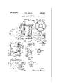
DISTILLA'I'ION APPARATUS Original Filed Aug. 5, 1937 s Sheets-Shee 1 INERT Oct. 19, 1943. E. H. FRENCH 2,332,215
DISTILLATION APPARATUS Original Filed Aug. 5, 1937 3 Sheets-Sheet 2 IINVENTOR Oct. 19, 1943. E. H. FRENCH 2,332,215
DISTILLATION APPARATUS Original Filed Aug. 5, 1957 3 Sheets-Sheet 3 INVENTOR.
remove any substances thereby precipitated, is preheated to a temperature below that at which decomposition of the liquid components occurs. The preheated liquid or solution then is spray vaporized or atomized Within a still maintained at a temperature at which, under the pressure conditions existing therein, the liquid is quickly vaporized. The resultant vapors promptly thereafter pass into intimate contact with a mass of inert contact material maintained at approximtely the temperature of the still, the said contact material preferably consisting of a mineral wool or glass wool so loosely packed that it offers little or no resistance to the passage therethrough of the vapors. The liquid particles in the vapors or mist are deposited or coalesce upon the surfaces of this inert material, while the true vapors freely pass therethrough. The arrangement of parts preferably is such that the fluids fiow downwardly through the scrubber material. the scrubber, or immediately upon leaving the latter, the vapors change direction sharply, while still being maintained at substantially their distillation temperature, whereby any coalesced liquid particle still present therein are thrown out. The vapors then flow quickly from the still to the first of a series of condensers. In each of the latter the vapors flow downwardly,diiferent fractions thereof being condensed in the respective condensers depending upon the conditions maintained therein, and upon the nature of the vapors beingcondensed, and are withdrawn from the bottomof the condenser in which condensed.
In the practice of the invention according to one modification, means are provided for maintaining the still and condenser system under high vacuum to facilitate operation of the still-scrubber unit at a temperature at which, during the extremely short period of existence of the vapors at'such temperatures, no decomposition of the heat-sensitive materials occur, even in the. presence ofthe highly heated contact materials mentioned. According to another, modification, meansare provided forintroducingan inertgas such as carbon dioxide, nitrogen, natural, gas, methane or hydrogen into the. still with the atomized solution in order. to facilitate the distillation of the solution at temperatures suificiently low to prevent decomposition of the organic compounds. The advantage :of this partial pressure r effect may be secured in operations conducted under atmospheric pressure as well as under .vacuum. a
To illustrate such modification, a petroleum oil to be refined such as in crude petroleum or a used lubricating grade of hydrocarbon oil, preferably after filtration or othertreatment to remove insoluble material, is preheated to an elevated temperature below that at which decomposition occurs, and preferably below about 570 F. The preheated oil then is spray-atomized into a still within a flowing stream of a suitable highly heated gas which is substantially inert or resistant to decomposition at the oil distillation temperature, such as methane, natural gas or'nitrogen. The inert gas is at a temperature which may be sufficiently high to superheat the preheated oil entering the still. The still may be under approximatelyatmospheric pressure, and at a temperature at which theoil is quickly vaporized Within the body of hot inert gas. The resultant vapors promptly contact a coalescing and stripping means hereinafter described which is maintained at ap roximately the distillation tempera- .ture of the oil.' Unvaporized oil particles are Within coalesced and separated from the mixed vapors and gases under conditions whereby countercurrent flow of the stripped vapors and the coalesced material is prevented. The stripped vapors then flow through a series of condensers such as hereinafter described and are fractionally condensed, the lubricating fractions being separately recovered. The uncondensed carrier and heating gas is withdrawn from the last condenser, and is reheated and recycled to the still under a selected uniform pressure and flow rate. The centrifugal type of scrubbing means shown in Fig. 5 of the accompanying drawings preferably is used when distilling hydrocarbon oils or other liquids at pressures around atmospheric or above, using circulating heating and carrier gas.
It is important in the practice of the present invention that coalescence of the liquid and solid particles present in the spray or mist delivered Within the still be efiectedpromptly after the spraying operation, by suitable means, such as a contact mass which itself is at a temperature substantially that of the mixed vapors, so that such coalescenceis accomplished while condensationof all vapors is prevented. The contact mass in the scrubber shouldbe so arranged as to offer substantially little or no resistance to the downward flow of the vapors therethrough. The subsequent sharp change of direction of therapidly flowing vapors assists to separate therefrom any traces of liquids and solids coalesced in the scrubher or dripping from the latter. No true filtering action is manifested.
The invention will now beillustrated in connection with the production of resin and fatty acids of high purity from alkaline pulping liquors produced in the pulping of Wood, such as is described in my United States Patent No. 1,997,171. These alkaline pulpingliquors, containing resins and oily substancesin the form of their watersoluble salts or soaps are treated with an acidic substance such as a mineral acid or an acid gas. The rosin and fatty acids, etc, are then dissolved in a suitable solvent, such as gasoline, kerosene, naphtha, or gas oil. Preferably the solvent is immiscible with water. If desired the solution of rosin and oily substances may be then treated in the cold with strong sulphuric acid to remove objectionable unsaturated compounds in wellknown manner, following which the residual acid and Water soluble reaction products are Washed from the solution of rosin with water. The solution is then filtered in the cold to remove precipitated matter or nigger therein.
In forming the aforesaid solution it is preferred to employ around 4 or more parts by weight of the solvent to each part by weight of the mixture of rosin and oily substances or fatty acids. Under these conditions certain objectionable color and odor-producing bodies deposit from the solutionand are removable, even prior to the sulphuric acidtreatment of the solution when such treatment is used. v
The filtered solution is then heated by suitable means to a'temperature suificiently high to vaporize the volatile constituents at the pressure existing in the distillation zone, but below the temperature at which substantial cracking and decomposition of the volatilized components can occur under the conditions of operation. When utilizing the present flash-vaporizing process and maintaining the still'under a vacuum of 28 to '29 inches of mercury, the solution is preheated to a temperature below around 315 C., and prefseal with the flanged margins 31 of the still wall and with an interposed gasket of suitable material, these parts being secured together by bolts or their equivent. A closure plate 41 having a central opening and carrying an outlet conduit 49 in alignment with conduit 43 also is secured to the plate 46 and still 3| by the said bolts. Conduit- 49 has a lateral member I extending through the wall of the furnace housing. The front end of the furnace has a stack 53 for Waste furnace gases. The rear end of the housing is provided at the top with an insulated, removable capor cover 55 adapted to house the upper end of the still, scrubber and associated parts. The cover 55 is removed whenever the scrubber is taken out for inspection or treatment of the contact material.
For condensing vapors flowing from the still there are provided a series of condensers 51, 59, BI, 62 and 63, so arranged and constructed that the vapors to be condensed flow downwardly in each successive condenser. Liquids condensed in the respective condensers flow from the. lower outlets thereof into corresponding receivers .65,
B1, 59, Ill, "II through valve-controlled conduits I3, or, alternatively, into auxiliary receivers I5, I1, 19, 89, and 8| through valve-controlled conduits 83 when the main receivers are being emptied. Each of said receivers is connected with a vacuum pump 55 through the conduit 81 and branch-controlled conduits asshown, and each has a valve-controlled liquid discharge line 88.
Vapor conduits 89 connect the lower portion of each condenser with the upper portion of the next successive condenser. Valve-controlled vapor outlet lines 9|, 92 from the last receivers H, 8I, lead to a vacuum pump (not shown) past valve 93, and conduct uncondensed gases from the system. Alternatively, when inert gases are recirculated in the system for their partial pressure effect in the still, valve 93 is closed, and a gas circulating pump 94 conducts the said gases to the spray nozzle in the still, from lines 9|, 92, through valve-controlled lines 95, 98, or from a source of supply of the said gases through line I 00. The line 98 passes through the furnace where the recirculated gases are again heated; and the line conducts the heated gases to the still and discharges them into the latter through an annular passage IElI surrounding the nozzle 35.
For preparing and pretreating the solution of organic material to be distilled, there is provided a vessel 95 having an inlet line 97 for'the crude material and solvent, and a bottom outlet line having a valve-controlled waste discharge line 99, and a solution discharge line connected with a second vessel I03 by a valve-controlled conduit I94 having therein a pump I95. A liquid outlet line ill! from vessel I03 has therein a valve-controlled waste discharge line I99 and a pump III. Line IGl is connected with the upper inlet end of condenser 63, the construction of the latter being such that the liquid from line IIl'I flows downwardly and then upwardly through the tubes therein in indirect heat-exchange relation with the vapors flowing through the condenser from the still. The thus-heated liquid then flows successively through the lin s M3 to the other condensers of the series, and finally flows from condenser 51 through line II5 to the preheater 29. A valve-controlled line II! leads liquid from the preheater to the liquid inlet-line 33 at the still.
Valve-controlled bypass line H6 permits bypassing of any condenser by any part or all of the liquid, when desired. A valve-controlled branch line II 9 connects the line II 5 directly with the inlet line 33 and permits bypassing the preheater by any or all of the liquid, where this is advantageous. The spray nozzle 35 is adapted to in troduce the liquid into the still in finely divided form under any selected pressure.
For removing from the still any unvaporized liquid in the eventitshould accumulate, a drain line I23 "connects the bottom of, the'still with a receiver I24 and auxiliary receiver I25,- each of the latter being connected with the vacuum line 81 as shown. For removing from the bottom of the scrubber-38 any coalesced mistor unvaporized liquid formed in the still and caught in or on thescrubber contact material a conduit I 21 connects the scrubber bottom with the drain line I23. A baflie I28 in the housing near the upper portion of the still directs the hot furnace gases around the rear end of, the still and scrubber to maintain .the sameat uniformly high temperatures. By regulatingthe dampers I5,- I1, the hot gases may be directed as desired over the pre heater and/or over either or both of the respective ends of the still.
Although the scrubber 38-ma-y. function as a filter for removing any filterable material prescut, that is not its primary purpose. In fact the usual finely divided filtering materials such as fullers earth, kaolin, absorbent clays, and the like, tend to obstruct the rapid flow cf vapors through and out of the high temperature scrub.- bing zone wherein unvaporized particles are 00- alesced. This is due to the relatively low percentage of voids present therein, as distinguished from glass wool, steel wool, glass beads, pieces of earthenware and the like employed by applicant as coalescing media. In the claims, the term solid scrubbing medium having a high percentage of voids and similar terms refer to coalescing media of the latter type, which allows free flow of the vapors through and from the hot scrubbing zone. In one instance, utilizing the apparatus described for distilling a 20% solution of rosin and fatty materials in naphtha having a boiling range, between 150? C. and 205 0., excellent results were secured in a distillation conducted at temperatures within the range from 260 C. to 275 C., under a vacuum of 28 inches of mercury, using in the scrubber a 24 inch depth of glass wool having over of 50% voids.
In the practice of the invention, utilizing the apparatus of Fig.1, the heat-sensitive organic materials to be distilled are introduced into the vessel together with the desiredamount of the solvent, which is thoroughly mixed therewith. The solution then is treated with around 2 to 6% of concentrated sulphuric acid in wellknown manner in order to remove objectionable unsaturated bodies. The mixture in vessel 95 is settled, and the water and sludge are withdrawn through line 99. The residual liquid in the vessel is then washed with water, the washings also being removed through line99. The washed solution is then pumped into storage tank I03. From there it is pumped by pump III to the preheater 29, passing successively through each of the condensers 63, 62, 6!, 59, and 51. Any or all of the condensers may be bypassed, if desired, through lines I Hi. The preheated solution flows from the preheater to the spray nozzle 35 through line II'I controlled by valve I30. The valve-controlled bypass line II9 permits the cooling or dilution when desired of the preheated solution flowing to the still. The vapors and atomized liquid particles formed in the still are quickly drawn into the hot scrubber .through its open upper end, and thence pass downwardly through the contact material to the scrubber bottom where the vapors abruptly change direction. Any coalesced liquids impinge or are deposited upon the said bottom, the hot stripped vapors being rapidly withdrawn from the scrubber through lines 43, 49, and M. Then they enter the condenser system, through which they pass in obvious manner, the vapors flowing downwardly in each condenser, so that any condensate flows in the same direction as the uncondensed vapors, and does not interfere with the free flow of the latter. The liquids condensed in the respective condensers flow downwardly to the receivers associated therewith, from which they can be withdrawn as desired. The vacuum pump 85 serves to vacuumize the receivers and the residue storage tanks I24I25 after the latter have been cut ofi the line for discharge of their contents,
and before again cutting them into the system.
Thus are prevented all substantial variations in the vacuum maintained in the main still-condenser system, such as occur when unvacuumized vessels are connected with such system and which would produce uncontrollable variations in the products being formed in the still, and in the fractions being condensed in the respective condensers. I
Figs. 2 and 3 show another type of still, similar in general to that of Fig. l, but in which the still and scrubber are square in transverse cross-section. In this modification thescrubber I3! is in the rear end section of the still, and
is formed by the side walls I and rear end wall I36 of thestill, and a front wall or baflle member I38 which makes a fluid-tight joint with the still bottom and which extends upwardly to a point spaced from the still top so as to permit free access of vapors in the still to the upper end of the scrubber; The latter is separated into'an inlet or contact compartment and an outlet compartment by the outlet line I39 having a flanged lower end cooperating with a flange in the inner wall of the scrubber tosupport a screen or screens I40 carrying a body of mineral wool or other mist-coalescing solids, I4I. Supporting members I42 secured to the still wall and to line I39 reinforce the screens. Liquid drain lines I44, I45, respectively connect the still and scrubber with receiver I 24. (See Fig. l.) The scrubber section of the still is removable from the furnace, being slideable on tracks I46, through a removable rear wall section I41 of the furnace housing.
Figs. 4 to 6 illustrate a vform'of the invention that is especially adapted for use in operations conducted at or around atmospheric pressure, and where inert gases are introduced into the still to facilitate operations at low temperatures obviating decomposition of the material being distilled. Here a scrubber I is mounted wholly within the furnace housing 'II. The scrubber communicates with the outlet end of the still I5I through conduit I52, which extends within the scrubber and has its discharge end centrally disposed therein and directed upwardly. The scrubber has a vapor outlet I54 in the upper end. Liquid drain lines I55, I51, lead respectively from the bottoms of the crubber'and still to a suitable container, such as the receiver I24 (Fig. l) The side walls of the scrubber I50 slope outwardly in a downward direction, so that any liquid particles impinging thereon freely flow to the drain line. Mounted upon the furnace housing is an electric motor I58, the armature shaft of which has anextension I60 extending through bearings carried by suitable bushings I62, I64, carried in thefurnace wall and'in the top of the scrubber. The extension also is provided with a central bearing carried by a centering spider I66 secured to the scrubber wall. A hollow cylindrical baffle number I68, having animperforate top and a central opening in its bottom to accommodate the conduit I52, is secured to the lower end of shaft I60 for rotation with the latter. The side walls of the number I68 are foraminous, and have secured thereto vertically disposed angle members I'IIladapted during rotation of the number I58 to impact the vapors and mist entering fromconduit I52 and to discharge them laterally'at high velocity against the walls of the rotatingmember I68 and of the scrubber I56. The other parts of the furnace and associated parts are in general the same as shown in Fig. 1. During operation the centrifugal action of the rapidly rotating member I68 causes the vapors and suspended liquid particles to impinge upon'the' heated .walls of the scrubber where any liquid particles coalesce, and the resultant liquid stream flows to the drain line I56 and is removed. The stripped vapors thus freed from liquids and while still at high temperatures are rapidly withdrawn and flow to the first condenser of the series hereinbefore described.
Figs. '1 and 8 illustrate stillv another form of distillation apparatus having-the scrubber or its equivalent'in the high-temperature distillation zone. Here the hot vapors leaving the atomiz-v ing nozzle 35 of the still enter the scrubber chamber I'lBthrough the spiral conduit IBM. The latter is disposed longitudinally of the scrubber and discharges fluids downwardly to a bottom outlet I82 spaced from thev bottom of the scrubber chamber, the hot vapors and suspended liquid particles beingsubjected to a centrifugal action as they flow downwardly to the bottom outlet I82, from-thence they rise upwardly outside of the conduit Iilil'under action of the main vacuum pump oonnected with the last condenser 63 (see Fig. l) and are quickly temperaturefdistillation zone, through outlet I84. Particles that are liquid at the temperatures within the scrubber I18 are coalesced on the bottom o f the scrubber'and are withdrawn therefrom through valve-controlled drain line I86, which line also drains any liquid deposited in the still I88;
Figs. 9 and 10 illustrate another type of stillscrubber assembly. Therein, the still 203] is mounted vertically upon checker work 2M within the furnace housing 202. 'The latter is heat-insulated and is provided with an auxiliary combustion chamber 254 having one or more burners 206, and a bafiie 201 to prevent direct flames from striking thebottom of the still. The flue gases leave the furnace through stack 258- having the damper 2G9. Surrounding the upper portion of the till 200 is apreheating coil 2I0'functioning similar to the preheater 29-of Fig. 1. The
inlet end of the coil is connected with line I I5 (see outlet end is connected with the 35. The latter is wardly to discharge highly heated vapors and mist towards the bottom of the still. Supported upon the sloping bottom of the still by members 2I2 and disposed vertically within and axially of the till-is a vapor outlet member2I4 of gen- Fig. 1), and the atomizing nozzle erally frusto-conicalshape, spaced from the side removed from thehighdirected downwalls of the still. ..An outlet line H6 is connected with the outlet of member 2 for conducting vapors therefrom to the series of condensers described in connection with Fig. 1. The lower margin of member 2M has a flange cooperating with a similar flange on inner wall of still 200 to support screens 2I5 that support a bed of solid contact or scrubbing material of the kind heretofore described. Radial supports 2|! connect the said supporting flanges. In thismodification, the rate of flow of the atomized material within the still increases during its flow through the contact material. This, together with the abrupt change of direction of the vapors leaving the scrubber, and the slight reduction in their rate of flow at this point in their path, facilitate complete removal therefrom of all liquid components that otherwise would impart undesirable color to the condensate subsequently produced from the vapors. Any liquids deposited in the still or scrubber bottom'are withdrawn through valvecontrolled line MB. A removable closure 2|! in the side wall of the still permits'inspection of the inside of still and scrubber, and the treatment or removal of the scrubber material when desired.
Figs. 11 to 15 illustrate forms of the invention involving the employment of a relatively thin lining of corrosion-resistant metal for all parts coming in contact with hot fluids capable of corroding the usual ferrous metals. Preferably those apparatus elements exposed to high temperatures, such as those around 260 C. or above, are constructed entirelyof corrosion-resistant metals or alloys such as nickel, stainless steel of the 18% Ni 8% Cr type, or Monel metal, while the elements exposed to lower temperatures, such as the condensers, pipes carrying cool liquids, etc., maybe made of these metals or of aluminum. However the cost of the large quantity of these metals required for apparatus constructed ontirely therefrom is very great.
' Applicant also has made the surprising discovery that it is possible to obtain the desired M corrosion-resistance and long life for this type of apparatus made of the ordinary grades of steel and like ferrous metals and alloys and designed to be exposed to corrosive fluids, by securing upon the exposed surfaces of the apparatus a thin sheet lining of the said corrosionresistant metal having unwelded, uncaulked joints. The lining may be secured to the adjacent walls of the element being lined therewith by any suitable means, such as by spot-welding,
or by bolting together flangedv margins thereof.
Still more surprising and unpredictable is applicants discovery, now fully demonstrated, that it is possible, by proceeding in the following manner, so to secure such thin metal inner lining upon the metal part to be protected that, although secured to the said part at only a limited number of spaced points, yet over long periods of service it successfully resists all forces acting upon it to induce its collapse, even when a high Vacuum is maintained on the still or other vessel thus lined.
At the same time this lining definitely prevents the corrosive fluids from reaching the corrodible metal walls of thevessel so lined.
In afiixingthe metal lining to the vessel, sections of the thin sheet metal lining having lapped margins are joined together when in place in the vessel by having their lap d ends interlapped together, as shown in Fig. 15, after which the parts forming the lapped assembly are pressed or impacted together to produce the type of joint (iii ordinarily known as a tinners lap. At spaced points along the line ofthese seams, as well as at other points in the lining, the same may be secured to the base metal of the vessel by spotwelding, by bolts of corrosion-resistant metal, or the equivalent. When linings are bolted in place, the inner surface of the vessel to be lined preferably is provided with angle members to which the lining may be secured as shown in Fig. 14in which case the lapped joint formed in thelining is not located in the said angle member. High vacuum fails either to dislodge or otherwise injure the lining, and the interior surface of the vessel is fully protected from corrosion.
Fig. ll illustrates, a still-scrubber assembly having inner linings of the type described. As shown, all parts coming in contact with hot vapors are lined or covered with sheets of corrosicn-resistant metal secured in place in the manner indicated. Such parts include the still, scrubber, vapor outlet conduits 43, 49 and Si, and the respective supporting members 240 and 233 for the scrubber and the screen 45. A lapped joint in the metal lining is indicated at 230 in Fig. 11, and on a somewhat larger scale in Figs. 13 and 15. The open-topped scrubber 39 is supported upon the cover plate 43 by the spaced vertical angle members 240. Secured to the scrubber walls are flanged supporting members 23i that cooperate with flanges on the lower end of outlet line 43 to support transverse members 233 carrying thescreens 45. Fig.1 14 shows a fragment of a still wall having suitably secured thereto a flange member 232. A lining sheet 234 of corrosion-resistant metal covers the inner wall surface and the flange 232. The lining is secured to the said flange by spaced spot welds 236. Both inner and outer surfaces of the scrubber and of the vapor conduit 43 are thus lined.
Thu it is seen that the distillation apparatus of the invention essentially includes an assembly of heated units, comprising a preheater, a spray vaporizing still, a contact separator or scrubber, and a vapor outlet conduit, all disposed within a unitary heat-insulated furnace housing that is provided with means for producing and distributing a high temperature heating medium to selected parts of the said assembly. The scrubber is removably mounted Within the furnace housing-and can be withdrawn or reached for replacing or cleaning the contact material. Thus, the top part of the housing can beremoved, whereupon the scrubber can be disconnected from the still and removed overhead. On the other hand, the still of Fig. 9 is provided with a removable closure in its side wall for use in cleaning or replacing the contact material.
Moreover the process features of the invention essentially comprise spray-vaporizing or atomizing a solution of a heat-sensitive organic material within a hot zone maintained at a temperature approximately as high or higher than that which the said solution possesses immediately prior to its atomization. The vapor mixture thus formed is quickly drawn from the still after passing through a scrubber or contact mass which oifers little or no resistance to they passage of the true vapors but which causes coalescence of finelydivided liquid or solid particles, thereby forming aggregates of. a size and weight sufficient to render them quickly and easily removable from the hot vapor stream when the latter is forced to change its direction suddenly while at the said highxtemperature. Thereafter the vapors are rapidlyiremovedfrom the still to the condensing.and'collcting' system, where the rosin, fatty acids; and solvent are successively condensed by heat-exchange with the solution pf crude charge liquor flowing to the preheater orheat-exchange 29.
Preferably the coalesced liquid isremoved from .the vapor stream .withlthe assistance of gravity or of regulated'ceiitrifugal forceiap'plied adja- 'cent the vapor outlet from the still. The more quickly these stripped'vapors"areremoved from the high temperature zone within the furnace housing, the purer and'freer from.'col'or"bodies and other impurities will bethedistillates subsequently formed. A'countercurrentliquid-vapor contact device, suchas a .de'phlgmating column is unsuitable for the treatment, of the hot vapors vwhere highly pure distillatea'ar desired; "The [requisite high speed of atomized vapors through andfromthehigh temperature'zone of the still Scrubber "assembly prf repiy is: effected 'under highvacuum-or by the use-ofa' rapidly recirculated strearnpf inert gas This" high speed flow fl'irtl'ierlisfacilitatedliy passlng tne'vapors downward through each of the condhsers and removing condensate therjefroi'nihthe direction of the .fiowof the vapors. I i I Ihefn'ov'el method he'reindscribed for apply.-
ihgf'to'a metal surface of lavessel or conduit fa 'slieet'metal' fining of corrosion-resistant metal claims, it refe the removal of nonvaporijred andloi" me anoma pm oge g no vaporous @0111 j u 12'? Sui a -m han sm suc scrubbing media of .the type described,
as solid rs I shai is -siw a h qsni iugalseparator shown inl fi .;4 to 8. The term indirect he is used i ihevq a msainl i usual sense to designate heat plied from an external Q smi -Pea s. lui is not directly mixed-with the vapors beingheated,
and doesn ot dilute the latter. 1
This application is a division of my copending application for Distillation process and apparatus filed August 5, 1937, Serial No. 157,561, now matured as Patent No. 2,278,543.
Variations may be resorted to within the scope of the following claims without departing from the spirit of the invention.
I claim:
l. Distillation apparatus, comprising a heating chamber; a distillation vessel disposed within said chamber and having a vapor outlet; means for spray-atomizlng within said vessel a fluid to be distilled, means for withdrawing distilled vapors from said vessel through said outlet; and means operatively associated with said vessel and interposed between the said atomizlng means and said vapor outlet and completely housed within said heating chamber and adapted to coalesce and strip from the high temperature tohereiinedis limited,
tight, not only resists t forth-in the body of fibrous inor peree'ntage of voids.
vapors flowing to said outlet'unvaporized'liquid and solidcomponents'and to prevent'countercurrentcontact of the vapors and unvaporized components stripped therefrom while present in said distillation vessel. i j 2. Apparatus as defined in claim- 1 together with a vacuum means connected with said vapor outlet and adapted to maintain a vacuum within said distillation vessel. a 3." Apparatus as defined in claim 1 wherein a ,centrifugal stripping'means is employed.
, 4. Distillation apparatus, comprising a furnace having a preheating chamber and a main heating chamber; means for controlling the direction of heat flow within the main heating chamber; a
distillation vessel disposed in the main heating chamber; spray-atomizing means inone end of the said distillation vessel; means operatively associated with the said vessel and completely housed within the said furnace and adapted to coalesce and'strip from the vapors leaving the said atomizlng means unvaporized' liquid and solid components while preventing 'countercu-rrent contact of the vapors and unvaporized components stripped therefrom; and means for withdrawing stripped vapors from the distillation vessel. i i "5. Apparatus as defined in claims, including a series'ofconden'sers connected with said distillation- "vessel and said coalescing and stripping meansjsna means for circulating a stream of inert gas-'throughthe distillation vessel, stripping means and series-of condensers.
) 6. Apparatus as defined in claim 4 whereinth'e coalescing and stripping means comprises a body and inert inorganic material having a high per- -centage of voids andoli ering vapor flow therethrough.
little resistance to 7; Apparatus as defined in claim 4 wherein 'thecoale'scing' and stripping means comprises a ganic material having a high 8' Apparatus as defined in claim ewherein the coalescing and stripping means is housed withir'i the'distillation vessel and includes a centrally-disposed vapor outlet conduit having an inletend'd'is'posed adjacent the-outlet from the coalescing and stripping means but spaced at a lower elevation than the latter.
9. Apparatus as defined in claim 4 including a "series of condensers connected with the outlet f om said still and said coalescing and stripping mean and-magmas circulating a stream of inert gas through the distillation vessel, coalescing -an'd'strippin'g means and series of conden the said coalescing and stripping means comprising a centrifugal "liquid-vapor separator,
and 'rheansfor regulating the separating capacity ofthesa id centrifugal separator.
10. Apparatus for distilling high-boiling heatsensitive liquids, comprising, respectively within a heat-insulated furnace housing, a preheater, an atomizlng chamber, means for heating the said heat-insulated furnace housing, and means for coalescing and stripping from vapors leaving the said atomizlng chamber entrained liquids and solids in suspension therein while preventing countercurrent contact of the stripped vapors and the coalesced liquids and solids.
11. Apparatus as defined in claim 10 wherein the said coalescing and stripping means comprises a chamber mounted in the said atomizing chamber and having an inlet adapted to direct incoming vapors downwardly, means in the lower portion of the said coalescing and stripping the said housing and having a vapor inlet in permanent communication witlrthe said still and adapted to discharge vapors within the said unit;
means associated withthetreating unit and disposed within said housing for coalescing finely- .divided liquid and solid particles in the vapors ,thus discharged and for separating the same from the vapors; ,means within the furnace for con- ,ducting the resultant stripped vapors from the coalescing means; a series of condensers connected with the last-named conducting means;
and vacnum means for Withdrawing the stripped vapors from the coalescing and strippingmeans through the said series of condensers.
1 3. Apparatus for refining hydrocarbon oils,
.whichcomprises means for preheating a fiowing body of such an oil containing alubricating fraction to a distillation temperature below that at which. it is substantially decomposed; a furnace;
a distillation chamber housed within said furnace; means for atomizing the preheated oil .within said chamber; means for maintaining said .chamber at a temperature approximating that of the preheated oil; means for regulating the vapor pressure of the said oil within said chamber; means within the furnace for quickly coalescing and removing from the resultant vapor stream non-vaporized liquid and solid components present therein and for maintaining the stripped vapors at the said high temperature,
.thelast-named means not materially retarding .the rate of flow of the vapors within the said chamber; means for quickly removing the stripped vapors from said chamber; and means for separately condensing from the stripped vapors a lubricating fraction of the oil thus refined.
14. Distillation apparatus, comprising a furnace having a preheating chamber and a main heating chamber; means for controlling the direction of the flow ofheatwithin the main heating chamber; a distillation vessel disposed in e the main heating chamber; fluid atomizing means .in the said distillation vessel; means operatively associated with the said vessel and completely housed within the said furnace, and adapted to means; and means for eeeaaw flowing the vapors to be condensed downwardly within each of the condensers and for removing the condensate from the vapors in the direction of flow of the latter, in the absence of countercurrent contact of the vapors and condensate.
15. Apparatus for distilling hydrocarbon oils comprising within a heatinsulated furnace housing, means for heating said housing, a preheater,
an atomizing chamber, means for coalescing and stripping from vapors leaving said atomizing chamber entrained liquids and solids in suspension therein While preventing countercurrent contact of the stripped vapors and the coalesced liquids and solids, and means for selectively regulating the flow of heat from saidheating means respectively to the said atomizing chamber and. to said coalescing andstripping means.
16. Distillation apparatus forthe refining of heat-sensitive hydrocarbon oils, which comprises a furnace housing; a still and a preheater in said housing; means for atomizing ,a volatilizable liquid within said still; means for heating the furnace and the elements therein to a selected high temperature; a vapor treating unitvwithin said housing and having a vapor inlet in permanent communication'with said still and adapted to discharge vapors within the said unit; means associated with said treating unit and, disposed Within said housing for coalescing finely divided 'liquid and solid particles inthe vapors thus discharged and for stripping the same from the vapors; means within the furnace for conducting the resultant stripped vapors from said coalescing and stripping means; a series of condensers connected with the last-named conducting withdrawing the stripped vapors from the coalescing and stripping means through said series of condensers,said withdrawing means including an inert gas recirculating system comprising a conduit connecting the last condenser of the series with said atomizing means, and a pump in said conduit having its 'inlet in communication with the last condenser of said series, and having its outlet in communication with said atomizing means.
17. Apparatus as defined in claim 16, wherein a portion of said conduit is disposed within said furnace housing.
EDWARD H. FRENCH.
Priority Applications (1)
| Application Number | Priority Date | Filing Date | Title |
|---|---|---|---|
| US414993A US2332215A (en) | 1937-08-05 | 1941-10-15 | Distillation apparatus |
Applications Claiming Priority (2)
| Application Number | Priority Date | Filing Date | Title |
|---|---|---|---|
| US15756137 US2278543A (en) | 1937-08-05 | 1937-08-05 | Distillation process |
| US414993A US2332215A (en) | 1937-08-05 | 1941-10-15 | Distillation apparatus |
Publications (1)
| Publication Number | Publication Date |
|---|---|
| US2332215A true US2332215A (en) | 1943-10-19 |
Family
ID=26854244
Family Applications (1)
| Application Number | Title | Priority Date | Filing Date |
|---|---|---|---|
| US414993A Expired - Lifetime US2332215A (en) | 1937-08-05 | 1941-10-15 | Distillation apparatus |
Country Status (1)
| Country | Link |
|---|---|
| US (1) | US2332215A (en) |
Cited By (2)
| Publication number | Priority date | Publication date | Assignee | Title |
|---|---|---|---|---|
| US2575051A (en) * | 1945-07-09 | 1951-11-13 | Buckeye Lab Corp | Process for purifying oil by distillation |
| US20050160552A1 (en) * | 2003-06-02 | 2005-07-28 | Takashi Yoshida | Cleaning apparatus |
-
1941
- 1941-10-15 US US414993A patent/US2332215A/en not_active Expired - Lifetime
Cited By (2)
| Publication number | Priority date | Publication date | Assignee | Title |
|---|---|---|---|---|
| US2575051A (en) * | 1945-07-09 | 1951-11-13 | Buckeye Lab Corp | Process for purifying oil by distillation |
| US20050160552A1 (en) * | 2003-06-02 | 2005-07-28 | Takashi Yoshida | Cleaning apparatus |
Similar Documents
| Publication | Publication Date | Title |
|---|---|---|
| US4140212A (en) | Cyclonic distillation tower for waste oil rerefining process | |
| AU1433797A (en) | Process and apparatus for the treatment of waste oils | |
| US2332215A (en) | Distillation apparatus | |
| US2278543A (en) | Distillation process | |
| US1616209A (en) | Method of and means for treating oils | |
| US2015085A (en) | Method of thermolizing carbonizable materials | |
| US1972157A (en) | Vacuum distillation | |
| US1823185A (en) | Process of purifying used crank case oil | |
| US2048140A (en) | Method for reclamation of absorption oil | |
| US1701988A (en) | Art of separating liquids having different boiling points | |
| US3138440A (en) | Process for cleaning gases | |
| US1594296A (en) | Apparatus for distilling oils | |
| US1784956A (en) | Distilling apparatus and method | |
| US1898579A (en) | Method and apparatus for absorption of constituents from gases and vaporous mixtures | |
| US2440707A (en) | Refining of naphthalene by distillation | |
| US2356952A (en) | Conversion of petroleum oils | |
| US1664977A (en) | Art of distilling lubricating oils | |
| US2065619A (en) | Oil purification and fractionation and apparatus for same | |
| US1833618A (en) | Process of dehydrating and purifying oil | |
| US1413260A (en) | Process of distilling crude petroleum and product thereof | |
| US1833691A (en) | Process for preparing crude oil for distillation into lubricating oils | |
| US1399792A (en) | Method of treating asphaltic oils | |
| US2092200A (en) | Treatment of acid sludge products | |
| US1860838A (en) | Method of preparing lubricants | |
| US1615407A (en) | Continuous distillation of crude petroleum oils |