US1853515A - Inflatable ball and method of making same - Google Patents
Inflatable ball and method of making same Download PDFInfo
- Publication number
- US1853515A US1853515A US408093A US40809329A US1853515A US 1853515 A US1853515 A US 1853515A US 408093 A US408093 A US 408093A US 40809329 A US40809329 A US 40809329A US 1853515 A US1853515 A US 1853515A
- Authority
- US
- United States
- Prior art keywords
- ball
- blank
- leaves
- edges
- circumferential wall
- Prior art date
- Legal status (The legal status is an assumption and is not a legal conclusion. Google has not performed a legal analysis and makes no representation as to the accuracy of the status listed.)
- Expired - Lifetime
Links
- 238000004519 manufacturing process Methods 0.000 title description 8
- 238000000034 method Methods 0.000 description 7
- 230000003014 reinforcing effect Effects 0.000 description 6
- 239000000463 material Substances 0.000 description 2
- 238000004826 seaming Methods 0.000 description 2
- 241000282619 Hylobates lar Species 0.000 description 1
- 239000000853 adhesive Substances 0.000 description 1
- 230000001070 adhesive effect Effects 0.000 description 1
- 239000004568 cement Substances 0.000 description 1
- 239000004575 stone Substances 0.000 description 1
Images

Classifications
-
- B—PERFORMING OPERATIONS; TRANSPORTING
- B29—WORKING OF PLASTICS; WORKING OF SUBSTANCES IN A PLASTIC STATE IN GENERAL
- B29D—PRODUCING PARTICULAR ARTICLES FROM PLASTICS OR FROM SUBSTANCES IN A PLASTIC STATE
- B29D22/00—Producing hollow articles
- B29D22/02—Inflatable articles
-
- B—PERFORMING OPERATIONS; TRANSPORTING
- B29—WORKING OF PLASTICS; WORKING OF SUBSTANCES IN A PLASTIC STATE IN GENERAL
- B29C—SHAPING OR JOINING OF PLASTICS; SHAPING OF MATERIAL IN A PLASTIC STATE, NOT OTHERWISE PROVIDED FOR; AFTER-TREATMENT OF THE SHAPED PRODUCTS, e.g. REPAIRING
- B29C65/00—Joining or sealing of preformed parts, e.g. welding of plastics materials; Apparatus therefor
-
- Y—GENERAL TAGGING OF NEW TECHNOLOGICAL DEVELOPMENTS; GENERAL TAGGING OF CROSS-SECTIONAL TECHNOLOGIES SPANNING OVER SEVERAL SECTIONS OF THE IPC; TECHNICAL SUBJECTS COVERED BY FORMER USPC CROSS-REFERENCE ART COLLECTIONS [XRACs] AND DIGESTS
- Y10—TECHNICAL SUBJECTS COVERED BY FORMER USPC
- Y10T—TECHNICAL SUBJECTS COVERED BY FORMER US CLASSIFICATION
- Y10T156/00—Adhesive bonding and miscellaneous chemical manufacture
- Y10T156/10—Methods of surface bonding and/or assembly therefor
- Y10T156/1002—Methods of surface bonding and/or assembly therefor with permanent bending or reshaping or surface deformation of self sustaining lamina
- Y10T156/1028—Methods of surface bonding and/or assembly therefor with permanent bending or reshaping or surface deformation of self sustaining lamina by bending, drawing or stretch forming sheet to assume shape of configured lamina while in contact therewith
- Y10T156/1033—Flexible sheet to cylinder lamina
Definitions
- a further object of the invention is to pro-.
- the present method of making sport balls from sheet rubber includes the use of orange-peel segments, the edges ofwhich are cemented together so as to form a ball.
- My invention is a considerable improvement over this known type of ball and this known method of manufacture. Instead of employing separate pieces of rubvention employs a plurality of cooperating leaves or triangular portions which are held in preliminary cooperating positions by a central wall which may be termed the circumferential wall of the blank from which a ball is to be made.
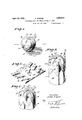
- Fig. l is a view of a preferred formof ball 7 ber which must be secured together, the inmade in accordance with my presentinvention.
- Fig. 2 is a view of a tubular blank forminga part of the invention.
- Fig. 3 shows an initialstep in the forming of a ball from a blank such as shown in Fig. 2.
- Fig. 4 shows a consecutive step in the forming of the ball.
- Fig, 5 is a view showing the manner of closing the second end of the ball.
- Fig. 6 is an enlarged fragmentary sectional view. showing the relative positions of the closed'ends of a ball when theclosing of the secondend is completed, this view cooperating with Fig. 5 in illustrating the method forming part of the invention.
- Fig. 7 is a fragmentary sectional view taken as indicated by the line 77 of Fig. 4, for showing an overlapped seam.
- Fig. 8 shows a curing mold with a seamed blank placed therein, preparatory to vulcanizing the ball.
- Fig. 9 is an elevational view of the ball, this view showing proportions which may be employed in the parts of the blank from which the ball is formed.
- Fig. 10 is a fragmentary view showing a portion of a blank,this view having the purpose of indicating alternative forms of leaves which may be formed alongthe edges of the blank.
- the preferred form of ball 15 embodying my invention includes'a centralcircumferential wall portion 16 and spherical end portions 17 composed of triangular wall portions orleaves 18 secured together along thecooperating adjacent edges 20 and 21, the ends or points 22 of the leaves or triangular portions 18 being covered by. a flat reinforcing member 23 which is prefer ably made in circular form.
- An important element of the invention is the blank 25 from which a ball such as indicated at 15 may be made.
- This blank 25 is preferably made from sheet rubber in tubular form and includes a central circumferential wall'portion 16 having a width 3V and a length which is'equivalent to the circumference of the tube of rubber from which the blank is made. vAdjacent to the'central circumferential wall portion 16,
- notches are cut, as indicated at 26, so as to form edge portions for the blank 25 consisting of adjacent triangular leaves 18, the outward extension of the leaves 18, or what may be termed the lengths thereof, being designated at E.
- the blank 25 may be made from rubber tubing, or a fiat sheet of raw rubber may have notches cut .in the edges thereof, the ends of the notched sheet being secured together so as to form a tubular blank of substantially the character shown in Fig. 2.
- An additional manner of forming the blank would be to form a tube from sheet rubber and then cut" notches in the ends of the wall 16 of the blank thus formed.
- Fig. 2 I have shown the blank 25 equipped with a filling valve consisting of a tube 27 which projects from a pocket 28 on the inner face of the blank ,25 through an opening or slit 29.
- Theblank is placed on a seaming form 3-0 which consists of a cylindrical block having a semi-spherical upper end 31.
- the blank 25 is pulled down on the form 30 to such position that the points or ends 22 of the triangular leaves 18 will meet in the manner shown in Fig. 3, when folded inwardlyover the semispherical end 31.- With the blank 25 in this position, the leaves are consecutively folded in, and the adjacent edges 20 and 21 are stuck together in overlapping relationship, either by use of cement or, if'the rubber is of a particular adhesive "nature, by removal of soap- 'stone from the cooperating edges 20 and 21 so that the edge portions of the rubber may stick together due to their ownadhesive char- 'acteristics.
- acircular piece of raw rubber 32 is placed across and over the contiguous 'ends 22 in the'manner shown in Fig. 4, it being understood that in the application of the reinforcing disc 23, the ordinary methods of securing portions of rubber together may be employed.
- the blank 25 is removed from the form 30, and the upper or finished end 33 is folded or bulged back into the circumferential wall portion 16, as would be done were it desired to turn the partly finished product inside out.
- the blank 25 is then replaced on the form 30 with the outer surface 34 of the finished end 33 lying in contact with the semi-spheriboal end 31 and with the reinforcin iece 23 lying against the upper end of the semispherical end 31.
- the circumferential wall 16 will be folded back on itself, along a central line of. fold 36.
- the leaves of the second or unfinished end of the ball, as indicated by the dotted lines 18', may then be folded in and joined together as explained relative to Fig. 3 and as indicated by full folded in and secured together in edge enlines 37 in Figs. 5 and 6, a reinforcing member 23 being placed over the contiguous ends of these leaves 18 of the second end of the ball, as indicated at 23.
- the leaves formed along the edges of a circumferential wall 51 may be of distorted triangular form, or, as shown at 52, may be given suchother forms as will enable them to otherwise contribute to the forming of a practically spherical end when leaves 18 is preferably substantially equal to the width W and the, over all width 0W of the blank 25is then substantially equal to one-half the circumference of the tube from which the blank is made or one-half the length of the central circumferential wall H portion'16.
- the leavesor triangular wall portions 18 are held together in their relative positions by the circumferential wall portion 16. This is a decided improvement over the old method of attaching loose or separate pieces todescribed, a circumferential wall having triangular portions along the edges thereof, the adjacent edges of said triangular portions being overlapped and secured together.
- a circumferential wall having triangular portions along the edges thereof, the adjacent edges of said triangular portions being cemented and vulcanized together in overlapped relationship, flat reinforcing pieces cemented and vulcanized over the contiguous ends of said triangular portions, and a filling valve whereby said ball may be in fiated.
- a circumferential wall having leaves formed along the edges thereof, the adjacent edges of said leaves being secured together whereby to close the ends of the ball.
- a blank'for forming a ball comprising a circumferential wall portion having adja- 10.
- 'Aiblank for forming a ball comprising a circumferential wall portion having adj acent triangular portions formed along each side thereof, the over-all width of said blank,
- tirangular portions being approximately equal to one-half the length of said circumferential wall portion.
- a blankifor forming a ball comprisingem a relatively thin-walled rubber tube having a central circumferential wall and edge walls on each side of said central wall, said edge walls consisting of adjacent leaves so formed that when in ed e en a ement the will con-e5 0 tribute to forming ends for the ball.
- a blank for forming a ball comprising a rubber tube having a central circumferen- Y tial wall portion and cooperating leaf portions along each side of said central wall, said ⁇ ? leaf portions being adapted for edge to edge engagement whereby to form the ends of the ball.
- method of making a ball comprising: forming a blank with a central circumferential wall and cooperating leaf portions along the sides of said circumferential wall; turning said leaves inwardly to positions of edge to edge engagement; and forming seams between the cooperating edges.
- a method of making a ball including: forming a blank with a circumferential wall portion and cooperating leaves projecting from the sides of said circumferential wall 7 portion; and joining the adjacent edges of said leaves, thereby closing the ends of the blank and producing a hollow ball structure.
- a method employ-ed in making a ball including forming a blank with a central circumferential wall portion and laterally projecting leaves along both edges of said central wall portion; placing the blank on a form having a semi-cylindrical upper end in such position that said leaves maybe folded over said cylindrical end into edge to edge engage-P ment; folding said leaves into edge to edge engagement over the semi-spherical end of said form; and forming seams betweenthe adjacent edges of said leaves. 16.
- a blank for forming a ball comprising a circumferential wall portion having leaf u portions formed along each side thereof, the leaf portions of each side being of such shape as to'form an approximately hemispherical Wall when the edges thereof are joined together.
- a circumferentialwall of flexible material having projecting leaves formed along an edge thereof, said leaves beingso shaped as to approximately 25 form part of a hollow sphere when the edges thereof are joined together.
- a circumferential Wall of flexible material having triangu- 80 lar leaves formed along an edge thereof.
Landscapes
- Engineering & Computer Science (AREA)
- Mechanical Engineering (AREA)
Description
April 12, 1932. EGERER "1,853,515
INFLATABLE BALL AND METHOD OF MAKING SAME Filed Nov. 18, 1929 2 Sheets-Sheet 1 1 AM WM- Ettorney April 12, 1932. r-. EGERER 1,853,515
INFLATABLE BALL AND METHOD OF MAKING SAME Filed Nov. 18, 1929 2 Sheets-Sheet 2 ii; liar/76y Patented Apr. 12, 1932 UNITED STATES FRANK EGEREB, OF LOS ANGELES, CALIFORNIA, ASSIGNOR TO W. J. VOIT RUBBER ATT @FFICE COMPANY, OF LOS AN GrIlJIElS, CALIFORNIA, A CORPORATION OF CALIFORNIA INFLATABLE BALL AND IMEIHGD OF MAKING- SAME Application filed November 18; 1929. Serial No. 408,093.
such wall having the peculiar characteristics in form particularly pointed out in the following specification.
A further object of the invention is to pro-.
18 vide a blank from which a ball may be quickly and perfectly made, the ball made from this blank being strong and sturdy and capable ofwithstanding the severe strains which are encountered in the use of sport balls.
Itisan object of the invention to provide a'blank for a rubber ball having a circumferential wall portion with leaves formed .adjacently along the edges of the circumferential wall position, these leaves being so formed that when the edges thereof are secured together approximately spherical ends for the ball will be formed. The present method of making sport balls from sheet rubber includes the use of orange-peel segments, the edges ofwhich are cemented together so as to form a ball. My invention is a considerable improvement over this known type of ball and this known method of manufacture. Instead of employing separate pieces of rubvention employs a plurality of cooperating leaves or triangular portions which are held in preliminary cooperating positions by a central wall which may be termed the circumferential wall of the blank from which a ball is to be made.
It is also an object of the invention to provide a new and simple method for the manufacture of sport balls.
Further objects and advantages of the invention will be made evident throughout the following part of the specification.
Referring to the drawings which are for illustrative purposes only,
Fig. l is a view of a preferred formof ball 7 ber which must be secured together, the inmade in accordance with my presentinvention.
Fig. 2 is a view of a tubular blank forminga part of the invention.
Fig. 3 shows an initialstep in the forming of a ball from a blank such as shown in Fig. 2.
Fig. 4 shows a consecutive step in the forming of the ball. i
Fig, 5 is a view showing the manner of closing the second end of the ball.
Fig. 6 is an enlarged fragmentary sectional view. showing the relative positions of the closed'ends of a ball when theclosing of the secondend is completed, this view cooperating with Fig. 5 in illustrating the method forming part of the invention.
Fig. 7 is a fragmentary sectional view taken as indicated by the line 77 of Fig. 4, for showing an overlapped seam.
Fig. 8 shows a curing mold with a seamed blank placed therein, preparatory to vulcanizing the ball. r i
Fig. 9 is an elevational view of the ball, this view showing proportions which may be employed in the parts of the blank from which the ball is formed.
Fig. 10 is a fragmentary view showing a portion of a blank,this view having the purpose of indicating alternative forms of leaves which may be formed alongthe edges of the blank. I
As shown in Fig. 1, the preferred form of ball 15 embodying my invention includes'a centralcircumferential wall portion 16 and spherical end portions 17 composed of triangular wall portions orleaves 18 secured together along thecooperating adjacent edges 20 and 21, the ends or points 22 of the leaves or triangular portions 18 being covered by. a flat reinforcing member 23 which is prefer ably made in circular form. An important element of the invention is the blank 25 from which a ball such as indicated at 15 may be made. This blank 25 is preferably made from sheet rubber in tubular form and includes a central circumferential wall'portion 16 having a width 3V and a length which is'equivalent to the circumference of the tube of rubber from which the blank is made. vAdjacent to the'central circumferential wall portion 16,
' tube adjacent to the central circumferential or along the sides thereof, notches are cut, as indicated at 26, so as to form edge portions for the blank 25 consisting of adjacent triangular leaves 18, the outward extension of the leaves 18, or what may be termed the lengths thereof, being designated at E.
It will be perceived that the blank 25 may be made from rubber tubing, or a fiat sheet of raw rubber may have notches cut .in the edges thereof, the ends of the notched sheet being secured together so as to form a tubular blank of substantially the character shown in Fig. 2. An additional manner of forming the blank would be to form a tube from sheet rubber and then cut" notches in the ends of the wall 16 of the blank thus formed. In Fig. 2 I have shown the blank 25 equipped with a filling valve consisting of a tube 27 which projects from a pocket 28 on the inner face of the blank ,25 through an opening or slit 29.
Theblank is placed on a seaming form 3-0 which consists of a cylindrical block having a semi-spherical upper end 31. The blank 25 is pulled down on the form 30 to such position that the points or ends 22 of the triangular leaves 18 will meet in the manner shown in Fig. 3, when folded inwardlyover the semispherical end 31.- With the blank 25 in this position, the leaves are consecutively folded in, and the adjacent edges 20 and 21 are stuck together in overlapping relationship, either by use of cement or, if'the rubber is of a particular adhesive "nature, by removal of soap- 'stone from the cooperating edges 20 and 21 so that the edge portions of the rubber may stick together due to their ownadhesive char- 'acteristics. After the leaves 18 have all been folded in and joined together along their adjacent edges, acircular piece of raw rubber 32 is placed across and over the contiguous 'ends 22 in the'manner shown in Fig. 4, it being understood that in the application of the reinforcing disc 23, the ordinary methods of securing portions of rubber together may be employed.
On completion of one end of the ball, the blank 25 is removed from the form 30, and the upper or finished end 33 is folded or bulged back into the circumferential wall portion 16, as would be done were it desired to turn the partly finished product inside out.
The blank 25 is then replaced on the form 30 with the outer surface 34 of the finished end 33 lying in contact with the semi-spheriboal end 31 and with the reinforcin iece 23 lying against the upper end of the semispherical end 31. When the blank 25 is thus placed on the form 30, the circumferential wall 16 will be folded back on itself, along a central line of. fold 36. The leaves of the second or unfinished end of the ball, as indicated by the dotted lines 18', may then be folded in and joined together as explained relative to Fig. 3 and as indicated by full folded in and secured together in edge enlines 37 in Figs. 5 and 6, a reinforcing member 23 being placed over the contiguous ends of these leaves 18 of the second end of the ball, as indicated at 23.
In the foregoing manner the ends of the blank are closed, thus producing a ball, such as indicated at 40 in Fig. 9, which is approximately, though not fully, circular in form,
this. ball 40 being ready for the final operation of curing the rubber. This is accomplished by placing the ball in a mold 41 having a spherical central opening 42 and having walls .43 which form a steam chamber or steam channels '44. The mold 41 is made of cooperating separable portions such as two cooperating halves. The mold 41 is closed :with the uncured ball'40 in place therein, and
air is then pumped into the uncured ball 40 through the valve tube 27, thus forcing the rubber walls of the ball into engagement with I the spherical walls which define the spherical opening 42 of the mold41. While the uncured ball is thus inflated within the mold, heat is applied thereto for the purposeof curing the rubber, this heat being preferably :90
produced by conducting steam through the channels 44. The curing of the ball under pressure within the spherical mold produces a spherical ball such as the finished ball 15 shown in Fig. 1. l 1
Although I prefer to employ triangular portions or leaves 18, I am aware that the shape of the leaves maybe varied. As shown at 50 in Fig. 10, the leaves formed along the edges of a circumferential wall 51 may be of distorted triangular form, or, as shown at 52, may be given suchother forms as will enable them to otherwise contribute to the forming of a practically spherical end when leaves 18 is preferably substantially equal to the width W and the, over all width 0W of the blank 25is then substantially equal to one-half the circumference of the tube from which the blank is made or one-half the length of the central circumferential wall H portion'16. It will be recognized that these dimensions may be varied considerably, although it is desired to substantially maintain a width OW equal to one-half the length of the circumferential {wall 16. 'The wall 16 may be made relatively narrow, or it may be made relatively wide, the variations in the width thereof requiring compensating variations in the extension of the leaves 18 so that a reasonably close approximation to g true sphere may be attained in the uncured all.
The leavesor triangular wall portions 18 are held together in their relative positions by the circumferential wall portion 16. This is a decided improvement over the old method of attaching loose or separate pieces todescribed, a circumferential wall having triangular portions along the edges thereof, the adjacent edges of said triangular portions being overlapped and secured together.
3. In a hollow game ball of the character described, a circumferential wall having triangular portions along the edges thereof, the
adjacent edges of said triangular portions being secured together, and flat reinforcing pieces extending across the contiguous ends of said triangular portions.-
4:. In a hollow game ball of the character described, a circumferential wallhaving triangular portions along the edges thereof, the adjacent edges of said triangular portions being cemented and vulcanized together in overlapped relationship, flat reinforcing pieces cemented and vulcanized over the contiguous ends of said triangular portions, and a filling valve whereby said ball may be in fiated.
5. In a hollow game ball of the character described, a circumferential wall in width substantially equal to one'sixth the circumference of the ball and having triangular portions along the edges thereof, the adjacent edges of said triangular portions being secured together.
6. In a hollow game ball of the character described, a circumferential wall in width substantially equal to one sixth the circumference of the ball and having triangular portions along the edges thereof, the adjacent edges of said triangular portions being cemented and vulcanized together in overlapped relationship, flat reinforcing pieces cemented and vulcanized over the contiguous ends of said triangular portions, and a filling valve whereby said ball may be inflated.
7. In a hollow game ball of the character described, a circumferential wall having leaves formed along the edges thereof, the adjacent edges of said leaves being secured together whereby to close the ends of the ball.
'cent'triangular portions-formed along each sidethereof.
8. In a hollow game ball of the character described, a circumferential wall having leaves formed along the-edges thereof, the adjacent edges of said leaves being overlapped and secured together whereby to (310883.1
the ends of the ball.
' 9. A blank'for forming a ball, comprising a circumferential wall portion having adja- 10. 'Aiblank for forming a ball, comprising a circumferential wall portion having adj acent triangular portions formed along each side thereof, the over-all width of said blank,
tirangular portions, being approximately equal to one-half the length of said circumferential wall portion.
"including the width of saidcircumferentialgg 7 wall portion and the outward lengths of said a 11. A blankifor forming a ball, comprisingem a relatively thin-walled rubber tube having a central circumferential wall and edge walls on each side of said central wall, said edge walls consisting of adjacent leaves so formed that when in ed e en a ement the will con-e5 0 tribute to forming ends for the ball.
12.- A blank for forming a ball, comprising a rubber tube having a central circumferen- Y tial wall portion and cooperating leaf portions along each side of said central wall, said}? leaf portions being adapted for edge to edge engagement whereby to form the ends of the ball.
13.14.; method of making a ball, comprising: forming a blank with a central circumferential wall and cooperating leaf portions along the sides of said circumferential wall; turning said leaves inwardly to positions of edge to edge engagement; and forming seams between the cooperating edges.
14. A method of making a ball, including: forming a blank with a circumferential wall portion and cooperating leaves projecting from the sides of said circumferential wall 7 portion; and joining the adjacent edges of said leaves, thereby closing the ends of the blank and producing a hollow ball structure. 15. A method employ-ed in making a ball, including forming a blank with a central circumferential wall portion and laterally projecting leaves along both edges of said central wall portion; placing the blank on a form having a semi-cylindrical upper end in such position that said leaves maybe folded over said cylindrical end into edge to edge engage-P ment; folding said leaves into edge to edge engagement over the semi-spherical end of said form; and forming seams betweenthe adjacent edges of said leaves. 16. A method. of making a forming a blank with a central circumferen tial wall portion and laterally projecting leaves along both edges of said central wall a semi-cylindrical upper end in such position" ball, including fthat said leaves may be folded over said cyi lindrical end into edge to edge engagement; f folding s'aid leaves into edge to edge engagement over the semi-spherical end of said '1 form; forming seams between the adjacent edges of said leaves; removing the partly closed blank from said form; inverting the closed end of said blank on said form; and 7 then turning in and seaming the leaves of the second end of said blank over the previously closed end of said blank Which rests in inverted position on said form.
17. A blank for forming a ball, comprising a circumferential wall portion having leaf u portions formed along each side thereof, the leaf portions of each side being of such shape as to'form an approximately hemispherical Wall when the edges thereof are joined together. V
'1 18. In a blank for forming a hollow game ball of the character described, a circumferentialwall of flexible material having projecting leaves formed along an edge thereof, said leaves beingso shaped as to approximately 25 form part of a hollow sphere when the edges thereof are joined together. p 19. In a blank for forming a hollow game ball of the character described, a circumferential Wall of flexible material having triangu- 80 lar leaves formed along an edge thereof.
In testimony whereof, I have hereunto set my hand at Los Angeles, California, this 2nd day of November, 1929.
, V FRANK EGERER.
Priority Applications (1)
| Application Number | Priority Date | Filing Date | Title |
|---|---|---|---|
| US408093A US1853515A (en) | 1929-11-18 | 1929-11-18 | Inflatable ball and method of making same |
Applications Claiming Priority (1)
| Application Number | Priority Date | Filing Date | Title |
|---|---|---|---|
| US408093A US1853515A (en) | 1929-11-18 | 1929-11-18 | Inflatable ball and method of making same |
Publications (1)
| Publication Number | Publication Date |
|---|---|
| US1853515A true US1853515A (en) | 1932-04-12 |
Family
ID=23614843
Family Applications (1)
| Application Number | Title | Priority Date | Filing Date |
|---|---|---|---|
| US408093A Expired - Lifetime US1853515A (en) | 1929-11-18 | 1929-11-18 | Inflatable ball and method of making same |
Country Status (1)
| Country | Link |
|---|---|
| US (1) | US1853515A (en) |
Cited By (6)
| Publication number | Priority date | Publication date | Assignee | Title |
|---|---|---|---|---|
| US3069725A (en) * | 1959-04-03 | 1962-12-25 | Andrew A Root | Apparatus and method for making foamed plastic containers |
| US3199871A (en) * | 1959-04-10 | 1965-08-10 | Barr Rubber Products Company | Ball and method of making same |
| DE1271590B (en) * | 1963-09-07 | 1968-06-27 | Rheinstahl Henschel Ag | Lock that can be operated from the outside with a key |
| US4079755A (en) * | 1976-05-04 | 1978-03-21 | Lans Gerald J V D | Inflatable pipe plug |
| US4151029A (en) * | 1975-04-30 | 1979-04-24 | Dunlop Limited | Method of making tennis balls |
| USD301161S (en) | 1987-01-29 | 1989-05-16 | Dunse Walter D | Game-ball |
-
1929
- 1929-11-18 US US408093A patent/US1853515A/en not_active Expired - Lifetime
Cited By (6)
| Publication number | Priority date | Publication date | Assignee | Title |
|---|---|---|---|---|
| US3069725A (en) * | 1959-04-03 | 1962-12-25 | Andrew A Root | Apparatus and method for making foamed plastic containers |
| US3199871A (en) * | 1959-04-10 | 1965-08-10 | Barr Rubber Products Company | Ball and method of making same |
| DE1271590B (en) * | 1963-09-07 | 1968-06-27 | Rheinstahl Henschel Ag | Lock that can be operated from the outside with a key |
| US4151029A (en) * | 1975-04-30 | 1979-04-24 | Dunlop Limited | Method of making tennis balls |
| US4079755A (en) * | 1976-05-04 | 1978-03-21 | Lans Gerald J V D | Inflatable pipe plug |
| USD301161S (en) | 1987-01-29 | 1989-05-16 | Dunse Walter D | Game-ball |
Similar Documents
| Publication | Publication Date | Title |
|---|---|---|
| US1568514A (en) | Playing ball | |
| US2623747A (en) | Inflatable athletic ball and method of making | |
| JP2022504796A5 (en) | ||
| US2129238A (en) | Inflated ball and method of its manufacture | |
| US1853515A (en) | Inflatable ball and method of making same | |
| US2494796A (en) | Inflatable game ball | |
| US1964008A (en) | Rubber ball | |
| US2221533A (en) | Athletic ball | |
| US2305409A (en) | Athletic game ball | |
| US2372382A (en) | Method of constructing safety inner tubes | |
| US1810556A (en) | Water wings | |
| US2750629A (en) | Device for the manufacture of molded rubber boots and similar articles | |
| US2461072A (en) | Meteorological balloon or similar article and method of making the same | |
| US2115543A (en) | Process of covering perforated rolls | |
| US2533742A (en) | Ring packing and method of making the same | |
| US2367374A (en) | Method of making inflatable athletic game balls | |
| US2025918A (en) | Ball manufacture | |
| US1518448A (en) | Football | |
| US35498A (en) | Improvement in school-globes | |
| US699089A (en) | Playing-ball. | |
| US1604044A (en) | Playing-ball cover | |
| US2512774A (en) | Method of making inner tubes | |
| US2009237A (en) | Football | |
| US830695A (en) | Process of and apparatus for manufacturing lined metallic hose. | |
| US1808091A (en) | Pneumatic tire tube |