US1853495A - Treadle mechanism - Google Patents
Treadle mechanism Download PDFInfo
- Publication number
- US1853495A US1853495A US427213A US42721330A US1853495A US 1853495 A US1853495 A US 1853495A US 427213 A US427213 A US 427213A US 42721330 A US42721330 A US 42721330A US 1853495 A US1853495 A US 1853495A
- Authority
- US
- United States
- Prior art keywords
- lever
- treadle
- fulcrum
- primary
- movement
- Prior art date
- Legal status (The legal status is an assumption and is not a legal conclusion. Google has not performed a legal analysis and makes no representation as to the accuracy of the status listed.)
- Expired - Lifetime
Links
- 238000005266 casting Methods 0.000 description 5
- 238000010276 construction Methods 0.000 description 1
- 239000000835 fiber Substances 0.000 description 1
- 238000009877 rendering Methods 0.000 description 1
- 239000011435 rock Substances 0.000 description 1
Images
Classifications
-
- A—HUMAN NECESSITIES
- A43—FOOTWEAR
- A43D—MACHINES, TOOLS, EQUIPMENT OR METHODS FOR MANUFACTURING OR REPAIRING FOOTWEAR
- A43D27/00—Machines for trimming as an intermediate operation
-
- A—HUMAN NECESSITIES
- A43—FOOTWEAR
- A43D—MACHINES, TOOLS, EQUIPMENT OR METHODS FOR MANUFACTURING OR REPAIRING FOOTWEAR
- A43D29/00—Machines for making soles from strips of material
-
- Y—GENERAL TAGGING OF NEW TECHNOLOGICAL DEVELOPMENTS; GENERAL TAGGING OF CROSS-SECTIONAL TECHNOLOGIES SPANNING OVER SEVERAL SECTIONS OF THE IPC; TECHNICAL SUBJECTS COVERED BY FORMER USPC CROSS-REFERENCE ART COLLECTIONS [XRACs] AND DIGESTS
- Y10—TECHNICAL SUBJECTS COVERED BY FORMER USPC
- Y10T—TECHNICAL SUBJECTS COVERED BY FORMER US CLASSIFICATION
- Y10T74/00—Machine element or mechanism
- Y10T74/20—Control lever and linkage systems
- Y10T74/20396—Hand operated
-
- Y—GENERAL TAGGING OF NEW TECHNOLOGICAL DEVELOPMENTS; GENERAL TAGGING OF CROSS-SECTIONAL TECHNOLOGIES SPANNING OVER SEVERAL SECTIONS OF THE IPC; TECHNICAL SUBJECTS COVERED BY FORMER USPC CROSS-REFERENCE ART COLLECTIONS [XRACs] AND DIGESTS
- Y10—TECHNICAL SUBJECTS COVERED BY FORMER USPC
- Y10T—TECHNICAL SUBJECTS COVERED BY FORMER US CLASSIFICATION
- Y10T74/00—Machine element or mechanism
- Y10T74/20—Control lever and linkage systems
- Y10T74/20528—Foot operated
-
- Y—GENERAL TAGGING OF NEW TECHNOLOGICAL DEVELOPMENTS; GENERAL TAGGING OF CROSS-SECTIONAL TECHNOLOGIES SPANNING OVER SEVERAL SECTIONS OF THE IPC; TECHNICAL SUBJECTS COVERED BY FORMER USPC CROSS-REFERENCE ART COLLECTIONS [XRACs] AND DIGESTS
- Y10—TECHNICAL SUBJECTS COVERED BY FORMER USPC
- Y10T—TECHNICAL SUBJECTS COVERED BY FORMER US CLASSIFICATION
- Y10T74/00—Machine element or mechanism
- Y10T74/20—Control lever and linkage systems
- Y10T74/20558—Variable output force
- Y10T74/2057—Variable input leverage
Definitions
- This invention relates to treadle mechanism of the type disclosed in United StatesLetters Patent No. 1,649,253, granted November 15, 1927, on an application filed in the name of u H. A. Rising, for machines in which it is desired to clamp a work piece in position to be operated upon, or to establishan mltial relation between awork pieceand a tool by consecutive movements of difierent character.
- One lmportant field of application of the invention is in connection with a sole rounding machine wherein a sole is engaged by a movable clamping member and held in position for presentation to the action of a rounding knife and for purposes of illustration the invention will be disclosed in this connection.
- One object of the present invention is to.
- the primary fulcrum is arranged to support the treadle lever during its initial movem nt and then to move with the treadle in its final movement, while a secondary fulcrum is arranged to support the treadle lever during its final movement and to move freely during the initialmovement of the lever.
- the secondary fulcrum is locked in operative position by means of a train of mechanism interposed between the two fulcrum members and including a pawl ratchet the operation of which is controlled by the movement of the primary fulcrum member.
- My invention also includes within its scope novel mechanism for causing the pawl to engage and disengage the ratchet, whereby the secondar fulcrum is locked promptly and effectively without appreciable lostmotion when the initial movement of the treadle is terminated, and as readily unlocked without delay and without requiring any attention on the part of the operator, when, in the return movement of the treadle, it is desired to shift back to the primary fulcrum.
- Another feature of theinvention consists in means for limiting the pressure which may be exerted by the operator upon the treadle lever when the latter is moving about its secondary fulcrum. Under these circumstances, the power arm of the lever is: so long that without safeguards a heavy operator might carelessly exceed the pressure required for proper operation of the mechanism and damage its parts. This is prevented, as herein shown, by providing the treadlelever with a foot pad arranged to yield at a predeter- I mined pressure and permit depressionto the fiber without further movement of the treadle. s
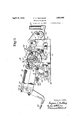
- FIG. 1 is a view of the mechanism in side elevation, with portions broken away;
- the treadle lever comprises a straight integral bar havlnga socket at its work end to receive the lower end of a vertical treadle rod 20 by which the clamp of a rounding machine may be operated, and at w its rear end a pivotally mounted foot pad 22.
- the foot pad 22 is yieldingly connected to the treadle lever in such a manner as to limit the pressure which may be exerted upon it by the operator and also to permit a full stroke to the floor in each depression or" the treadle.
- the rear end of the lever 18 is forked to receive a journal pin 24 upon which the foot pad 22 is mounted.
- the foot pad extends upwardly above the journal pin 24, where it is forked to receive a transverse pin 29 upon whichswivels the eye of a rod 28.
- the rod 28 projects forwardlythrough an oversize bore in an ear 26 projecting upwardly from the lever 18.
- a compress on spring 30 encircles the forward end V ofthe rod 28- and is held'under adjustable tension by nuts 32 threaded upon the end of the rod 28.
- the initial, position of the foot pad 22 is determined and forward movement of the rod 28 limited by the engagement of a collar upon the rod with the face ofthe ear 26.
- the nuts 32 may be set, for example, to compress'the spring 30 so that it will not yield until the operator has exerted a presi sure of 150 pounds, whereupon the spring 30 compresses, allowing the foot pad to swing about the axis of the pin 24 without further movement of the lever 18 and without subjecting it to a substantially increased pressure.
- The-primary fulcrum member'for the treadle lever is arranged to support thelever by contact with its under face at a point near the power end of the lever.
- the casting 1O is provided with a boss 36 in which is formed a transverse bore in which is mounted a hori-' zontal shaft 38.
- a cylindrical hub 42 is mounted to turn. upon the shaft 38 and. pro
- the arm 44 carries a transverse stud 46 upon which is mounted a roller 48.
- the inner end of theshaft 38 is extended beyond the arm 44 and surrounded by a sleeve 50 u on which is arranged a torsion spring 52. no end of the torsion spring extends under the stud 46 while the other end of the spring engages an outwardly-extending arm 54 formed integralwith the casting 10.
- the spring is so wound'as to tend always to swing the arm 44 and its connected parts in a clockwise direction (Fig. 1).
- the secondary fulcrum member'of the lever 18 includes the forked lever 16 already mentioned. This is pivotally connected to the lever 18. near the Work end of the latter, by aconnecting pin 60.
- the lever 16 extends rearwardly beyond the axis of its journal pin 14, where it is provided with a gear segment 62.
- the segment 62 is arranged to mesh with a pinion 64 formed'integrally with a stem 66 which is mounted in bearings in a bracket 68 extending upwardly from the base casting 10.
- the stem 66 is shouldered to receive the hub 71 of a ratchet disk 70.
- the hub of the ratchet disk is fastened to the stem 66 by a key 7 2, as shown in Fig.
- The'gear segment 62 is provided with a stud 63 which is arranged to contact with a stationary abutment on the bracket 68 and so limit the movement of the rocker lever 16in a counter clockwise direction about the axis of its journal pins 14.
- the stud 63 and its cooperating abutment therefore, prevent suiiicient angular movement of the rocker lever 16 to carry the gear segment 62 out of mesh'with the pinion 64 and thus prevent the possibility of disturbing the timing of this gearing.
- the mechanism herein shown includes means for locking the ratchet disk whenever the initial movement of thelever 18 is arrested by encountering increased resistance through the rod 20, as when the clamps make preliminary engagement with thesole presented to the rounding machine.
- a pawl is mounted upon a stationary portion of the bracket 68 upon a stud 82 and is normally urged toward the ratchet j ecting from a portion of the base casting'and arranged to act upon the lower" side of the ratchet disk.
- the two pawls 80 and 8% are set circumferentially half a tooth apart so that lost motion in the mechanism is reduced to this extent.
- the pawls 80 and 84 are normally maintained in an inoperative position out of contact with the ratchet disk by a cylindrical cage or mask 74 having a hub 76 mounted to turn upon the hub 71 of the ratchet disk.
- the mask 7 4 is connected to the arm of the primary fulcrum member by means of a curved link 90 pivotally secured by a stud 88 to the face of the mask at oneend and at its other end adjustably connected to a circumferenby the engagement of a lug 91 projecting from the end of the link 90 with a fixed abutment 93 projecting from the upstanding wall of the base casting.
- torsion spring 52 which acts to swing the primary fulcrum member will always return the mask to its predetermined initial position.
- the lower end of the linkv 90 may be adj ustably connected to the slot in the arm 40 so as to insure movement of the mask without lost motion when the arm 40 is moved.
- the treadle 18 extends in a straight line from the axis of its secondary fulcrum, past the axis of its primary fulcrum and to its point of connection with the foot pad, so that there is no tendency to twist or cramp in operation.
- This desirable feature of construction is'secured by arranging the locking mechanism, including the ratchet disk and gearing, in offset relation at one side of the path of movement of the lever.
- a clamping member is connected to the treadle rod 1 20 and that during the initial movementof the treadle while it is moving upon its primary fulcrum member with a ratio of substantially l to 3, the clamp is moved rapidly into initial contact with a sole positioned on the work table of the machine.
- the lever 16' which constitutesthe rocking secondary fulcrum member turns freely on the axis of its journal pin 14 and the gear segment 62 spins the pinion 64 and the connected ratchet disk.
- Treadle mechanism comprising a lever having a primary fulcrum mounted for movement about a fixed axis outside thelever, a secondary fulcrum mounted for movement about another fixed axis, and means constructed and. arranged to lock said secondary fulcrum in stationary position when said pri mary fulcrum is moved.
- Treadle mechanism comprising a lever
- Treadle mechanism comprising a lever, movable primary and secondary fulcrum membersmounted adjacent thereto and connected by a train of mechanism including a lock, the movement of the primary fulcrum member acting through said train to render the lock effective to hold the secondaryfulcrum member stationary.
- Treadle mechanism comprising a lever,a yieldingly supported primary fulcrum member adjacent to the power end of the lever, a secondary fulcrum member located adjacent to the work end of the lever, said fulcrum members being connected by a train of mechs anism including a lock arranged to be rendered effective by the movement of the primary. fulcrum member to hold the secondary fulcrum member stationary.
- Treadle mechanism comprising a lever, a yieldingly supported primary fulcrum member adjacent to the power end of the lever, and a secondary fulcruinmember located adjacentto the Work end of the lever,
- fulcrum members being connected by a train of mechanism including a ratchet disk, a pawl for locking said disk, a mask for rendering said pawl inoperative, and connections between said primary fulcrum member and the mask for controlling the position of the latter.
- Treadle mechanism comprising a lever, a primary fulcrum member mounted for movement at the conclusion of the initial movement of the treadle, a secondary fulcrum member connected to the lever and freely moved thereby in its initial movement, and locking mechanism associated with said fulcrum members and arranged to be rendered operative to lock said secondary fulcrum member in stationary position during the final movement of the lever.
- Treadle mechanism comprising a lever
- a primary fulcrum member arranged tosupport said lever yieldingly at a'point adjacent to its power end, a rocking secondary fulcrum member. connected at one end to said lever at a point adjacent to the work end of the lever and having a gear segment at its other end, and means actuated? by the movement of s'aid'primary fulcrum member for locking said gear segment to hold said sec: ondary fulcrum member stationary.
- Treadle mechanism including a lever, a primary fulcrum member arranged yield.- ingly to support said lever, a rocking'secondary fulcrum member connected at one end to a point on said lever and having a gear segment at its other end, a pinion meshing with said segment, a ratchet disk fast to the pinion, pawls for locking said ratchet disk and 'a mask for controlling the operation of the pawls operated by said primary fulcrum member.
- Treadle mechanism comprising a lever mountedfor initial movement upon a primary fulcrum, means for guiding thework end of' the lever in an are having a center other than that of said prlmary fulcrum, and means for establishing a secondary fulcrum for the lever in said are when its work endencounters increased resistance.
- Treadle mechanism comprising a lever, a primary fulcrum member for, yieldingly supporting; said lever, means for'ad justably determining the normal position of said ful-' crum member, a secondaryfulcrum member for the. lever freely. movable while, the lever moves upon, said, primary fulcrum member, and connections between said fulcrum members for locking said secondary fulcrum member; 7 g
- Treadle mechanism comprising a lever, primary and secondary, fulcrum members therefor, and an interposed train of mechanism. including a ratchet disk and pawl effective to lock said secondary. fulcrumv member, a mask for holding said pawl initially in inoperative position, and adjustable connecting mechanism interposed between said primary fulcrum member andfsaid mask for controlling the position of the latter.
- Treadle mechanism comprising a lever, primary and secondary fulcrum members associatedtherewith,and a train of mechanism interposed between said. fulcrum members including a ratchet disk and pawl. effective to lock said secondary fulcrum member, a mask movable to retractor release said pawl controlled in its movement by said primary fulcrum member, and means for positively determining the initial position of the mask.
- Treadle mechanism comprising a lever, a' rocker member connected thereto and hav ing a gear segment thereon, a pinion meshing with the; segment, a primary fulcrum member movable atth e conclusion of the initial movement of the treadle, a connecting trainof mechanism operated by said primary fulcrum member, to lock said rocker member, and means for limiting the movement of said rocker member independentlyv of said connectingtrain.
- Treadle mechanism comprising a lever, primary and secondary fulcrum members associated with said lever, one of said mem bers having a gear segment movable in a path located atone side of the lever, a ratchet disk operated by said segment, a pawl cooperating with said ratchet disk to lock said secondary fulcrum member, and means for controlling the pawl operated by said primary fulcrum member.
- Treadle mechanism comprising a lever, a primary fulcrummember located near. the power end of the lever and movable with the lever in its final movement, a secondary fulcrum member located near the work end of the lever and movable during the initial movement of the lever, a rotary member in operative relation thereto and arranged to be turned during the initial movement of the lever,:and ITIGELIISICOIItIOllGd by said primary fulcrum member for arresting the turning movement of said rotary member thereby to lock said secondary fulcrum member.
- Treadle mechanism comprising a lever, a pair of fulcrum members acting upon said lever at spaced points and movable one after the other,and a connecting train of'mechanism interposed between said members and including a lock arranged to be actuated by
Landscapes
- Mechanical Operated Clutches (AREA)
Description
Q Filed Feb. 10, 1930 2 Sheets-Sheet April 12, 1932.
F. E. BERTRAND TREADLE MECHANISM Filed Feb. 10, 1930 2 Sheets-Sheet 2 Patented Apr. 12, 1932 SATES FREDERIG E. BERTRAND, 0F LYNN, MASSACHUSETTS, ASSIGNOR T0 UNITED SHOE MACHINERY CGRPORATION, OF PATER SON, NEW JERSEY, A CORPORATION OF NEW JERSEY TREADLE MECHANISM Application filed February 10, 1930. Serial No. 427,213.-
This invention relates to treadle mechanism of the type disclosed in United StatesLetters Patent No. 1,649,253, granted November 15, 1927, on an application filed in the name of u H. A. Rising, for machines in which it is desired to clamp a work piece in position to be operated upon, or to establishan mltial relation between awork pieceand a tool by consecutive movements of difierent character. One lmportant field of application of the invention is in connection with a sole rounding machine wherein a sole is engaged by a movable clamping member and held in position for presentation to the action of a rounding knife and for purposes of illustration the invention will be disclosed in this connection.
The etlicient operation of sole rounding machines requires a clamping action upon the sole of considerable intensity. here a treadle is utilized for this purpose, it is desirable to provide for an initial movement of its work end at high speed and low mechanical advantage and a final movement at low speed and high mechanical advantage. In
view of the foregoing, my invention also contemplates improvements in treadle mechanism, of the type disclosed in copending application Serial No. 152,426, filed December 1, 1929, in the name of H. A. Rising, em-
ploying a single operating lever arranged for movement first about a primary fulcrum located to give a low ratio of power arm to work arm, and then about a secondary fulcrum located to give a high ratio of power arm to work cirm. In this way the total stroke of the treadle may be cut down in length, and this is desirable both from the standpoint of the operator and because it facilitates compactness of. design.
One object of the present invention is to.
provide improved mechanism for bringing axis outside the lever, a secondary fulcrum mounted for movement about another fixed axis and means constructed and arranged to lock said secondary fulcrum in stationary position when said primary fulcrum is moved. Thus, the primary fulcrum is arranged to support the treadle lever during its initial movem nt and then to move with the treadle in its final movement, while a secondary fulcrum is arranged to support the treadle lever during its final movement and to move freely during the initialmovement of the lever.
Preferably, and in accordance with another feature of the invention, the secondary fulcrum is locked in operative position by means of a train of mechanism interposed between the two fulcrum members and including a pawl ratchet the operation of which is controlled by the movement of the primary fulcrum member.
My invention also includes within its scope novel mechanism for causing the pawl to engage and disengage the ratchet, whereby the secondar fulcrum is locked promptly and effectively without appreciable lostmotion when the initial movement of the treadle is terminated, and as readily unlocked without delay and without requiring any attention on the part of the operator, when, in the return movement of the treadle, it is desired to shift back to the primary fulcrum.
Another feature of theinvention consists in means for limiting the pressure which may be exerted by the operator upon the treadle lever when the latter is moving about its secondary fulcrum. Under these circumstances, the power arm of the lever is: so long that without safeguards a heavy operator might carelessly exceed the pressure required for proper operation of the mechanism and damage its parts. This is prevented, as herein shown, by providing the treadlelever with a foot pad arranged to yield at a predeter- I mined pressure and permit depressionto the fiber without further movement of the treadle. s
These and other features of the invention will behest understood and appreciatedfrom the'following description of a preferred embodiment thereof, selected for purposes of illustration and shown in the accompanying drawings, in which Fig. 1 is a view of the mechanism in side elevation, with portions broken away;
- set screw.
are connected by an overhead web 17" and their inner faces are finished to form guides for the treadle lever 18-. The treadle lever comprises a straight integral bar havlnga socket at its work end to receive the lower end of a vertical treadle rod 20 by which the clamp of a rounding machine may be operated, and at w its rear end a pivotally mounted foot pad 22.
The foot pad 22 is yieldingly connected to the treadle lever insuch a manner as to limit the pressure which may be exerted upon it by the operator and also to permit a full stroke to the floor in each depression or" the treadle. For this purpose, the rear end of the lever 18 is forked to receive a journal pin 24 upon which the foot pad 22 is mounted. The foot pad extends upwardly above the journal pin 24, where it is forked to receive a transverse pin 29 upon whichswivels the eye of a rod 28. The rod 28 projects forwardlythrough an oversize bore in an ear 26 projecting upwardly from the lever 18. A compress on spring 30 encircles the forward end V ofthe rod 28- and is held'under adjustable tension by nuts 32 threaded upon the end of the rod 28. The initial, position of the foot pad 22 is determined and forward movement of the rod 28 limited by the engagement of a collar upon the rod with the face ofthe ear 26. The nuts 32 may be set, for example, to compress'the spring 30 so that it will not yield until the operator has exerted a presi sure of 150 pounds, whereupon the spring 30 compresses, allowing the foot pad to swing about the axis of the pin 24 without further movement of the lever 18 and without subjecting it to a substantially increased pressure.
' The-primary fulcrum member'for the treadle lever is arranged to support thelever by contact with its under face at a point near the power end of the lever. The casting 1O is provided with a boss 36 in which is formed a transverse bore in which is mounted a hori-' zontal shaft 38. A cylindrical hub 42 is mounted to turn. upon the shaft 38 and. pro
vided with an upstanding arm at its outer end and an upstanding arm 44 at its inner end. The arm 44 carries a transverse stud 46 upon which is mounted a roller 48. The inner end of theshaft 38 is extended beyond the arm 44 and surrounded by a sleeve 50 u on which is arranged a torsion spring 52. no end of the torsion spring extends under the stud 46 while the other end of the spring engages an outwardly-extending arm 54 formed integralwith the casting 10. The spring is so wound'as to tend always to swing the arm 44 and its connected parts in a clockwise direction (Fig. 1). The normal position of these parts isadjustably determined by a set screw 58 which is arranged to bear against and which is threaded into an arm 56 which projects forwardly from the hub 42. It will be seen, therefore, that the primary fulcrum member is at all times maintained in an initial position determined by the set screw 58, in contact with the under side of the lever 18, and free to swing in a. counter clockwise direction against the tension of the torsion spring 52when the treadle is subjected to sufficient pressure to overcome the resistance of this spring.
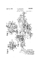
The secondary fulcrum member'of the lever 18 includes the forked lever 16 already mentioned. This is pivotally connected to the lever 18. near the Work end of the latter, by aconnecting pin 60. The lever 16 extends rearwardly beyond the axis of its journal pin 14, where it is provided with a gear segment 62. The segment 62 is arranged to mesh with a pinion 64 formed'integrally with a stem 66 which is mounted in bearings in a bracket 68 extending upwardly from the base casting 10. The stem 66 is shouldered to receive the hub 71 of a ratchet disk 70. The hub of the ratchet disk is fastened to the stem 66 by a key 7 2, as shown in Fig. 4, so that the pinion 64 and the ratchet disk 70 turn as one piece about the axis of the stem 66. The'gear segment 62 is provided with a stud 63 which is arranged to contact with a stationary abutment on the bracket 68 and so limit the movement of the rocker lever 16in a counter clockwise direction about the axis of its journal pins 14. The stud 63 and its cooperating abutment, therefore, prevent suiiicient angular movement of the rocker lever 16 to carry the gear segment 62 out of mesh'with the pinion 64 and thus prevent the possibility of disturbing the timing of this gearing.
t will be apparent that if the rocker lever 16 is locked in position it will act as a secondary fulcrum for the lever 18, which will then move about the axis of the connecting pin 60. "The mechanism herein shown includes means for locking the ratchet disk whenever the initial movement of thelever 18 is arrested by encountering increased resistance through the rod 20, as when the clamps make preliminary engagement with thesole presented to the rounding machine. To this end, a pawl is mounted upon a stationary portion of the bracket 68 upon a stud 82 and is normally urged toward the ratchet j ecting from a portion of the base casting'and arranged to act upon the lower" side of the ratchet disk. The two pawls 80 and 8% are set circumferentially half a tooth apart so that lost motion in the mechanism is reduced to this extent.
The pawls 80 and 84; are normally maintained in an inoperative position out of contact with the ratchet disk by a cylindrical cage or mask 74 having a hub 76 mounted to turn upon the hub 71 of the ratchet disk. The mask 7 4 is connected to the arm of the primary fulcrum member by means of a curved link 90 pivotally secured by a stud 88 to the face of the mask at oneend and at its other end adjustably connected to a circumferenby the engagement of a lug 91 projecting from the end of the link 90 with a fixed abutment 93 projecting from the upstanding wall of the base casting. It will be apparent also that A the torsion spring 52 which acts to swing the primary fulcrum member will always return the mask to its predetermined initial position. The lower end of the linkv 90 may be adj ustably connected to the slot in the arm 40 so as to insure movement of the mask without lost motion when the arm 40 is moved.
It will be noted that the treadle 18 extends in a straight line from the axis of its secondary fulcrum, past the axis of its primary fulcrum and to its point of connection with the foot pad, so that there is no tendency to twist or cramp in operation. This desirable feature of construction is'secured by arranging the locking mechanism, including the ratchet disk and gearing, in offset relation at one side of the path of movement of the lever.
Where the treadle mechanism of my invention is used in connectionwith a rounding machine, it will be understood that a clamping member is connected to the treadle rod 1 20 and that during the initial movementof the treadle while it is moving upon its primary fulcrum member with a ratio of substantially l to 3, the clamp is moved rapidly into initial contact with a sole positioned on the work table of the machine. During the initial movement of the treadle lever, the lever 16' which constitutesthe rocking secondary fulcrum member turns freely on the axis of its journal pin 14 and the gear segment 62 spins the pinion 64 and the connected ratchet disk. 'When the clamping member encounters the sole, the increased resistance temporarily arrests the upward movement of the treadle rod 20, so that continued depres-" sion of the treadle lever causes the primary fulcrum member to rock in a counter clockwise direction against the tension of the spring 52. This movement of theprimary becomes the axis about which the treadle lever moves, 7 Continued depression 'of the treadle thereafter swings it about its secondary fulcrum ata ratioof approximately 8 to 1 and forces the clamping member against the sole with a powerful pressure and holds it firmly in place. 8 v V Having thus described my invention, what I claim as new and desire to secure by Letters Patent is:
1. Treadle mechanism comprising a lever having a primary fulcrum mounted for movement about a fixed axis outside thelever, a secondary fulcrum mounted for movement about another fixed axis, and means constructed and. arranged to lock said secondary fulcrum in stationary position when said pri mary fulcrum is moved.
2. Treadle mechanism comprising a lever,
movable primary and secondary fulcrum members for said lever, and a train of mechanism interposed between said fulcrum members including locking mechanism constructed and arranged to lock said secondary fulcrum member in a stationary position when the primary fulcrum member is moved." '3. Treadle mechanism comprising a lever, movable primary and secondary fulcrum membersmounted adjacent thereto and connected by a train of mechanism including a lock, the movement of the primary fulcrum member acting through said train to render the lock effective to hold the secondaryfulcrum member stationary. I 4. Treadle mechanism comprisinga lever,a yieldingly supported primary fulcrum member adjacent to the power end of the lever, a secondary fulcrum member located adjacent to the work end of the lever, said fulcrum members being connected by a train of mechs anism including a lock arranged to be rendered effective by the movement of the primary. fulcrum member to hold the secondary fulcrum member stationary.
5. Treadle mechanism comprising a lever, a yieldingly supported primary fulcrum member adjacent to the power end of the lever, and a secondary fulcruinmember located adjacentto the Work end of the lever,
said. fulcrum members being connected by a train of mechanism including a ratchet disk, a pawl for locking said disk, a mask for rendering said pawl inoperative, and connections between said primary fulcrum member and the mask for controlling the position of the latter.
6. Treadle mechanism comprising a lever, a primary fulcrum member mounted for movement at the conclusion of the initial movement of the treadle, a secondary fulcrum member connected to the lever and freely moved thereby in its initial movement, and locking mechanism associated with said fulcrum members and arranged to be rendered operative to lock said secondary fulcrum member in stationary position during the final movement of the lever. v
'Z. Treadle mechanism comprising a lever,
a primary fulcrum member arranged tosupport said lever yieldingly at a'point adjacent to its power end, a rocking secondary fulcrum member. connected at one end to said lever at a point adjacent to the work end of the lever and having a gear segment at its other end, and means actuated? by the movement of s'aid'primary fulcrum member for locking said gear segment to hold said sec: ondary fulcrum member stationary.
8. Treadle mechanism including a lever, a primary fulcrum member arranged yield.- ingly to support said lever, a rocking'secondary fulcrum member connected at one end to a point on said lever and having a gear segment at its other end, a pinion meshing with said segment, a ratchet disk fast to the pinion, pawls for locking said ratchet disk and 'a mask for controlling the operation of the pawls operated by said primary fulcrum member. v r
9; Treadle mechanism comprising a lever mountedfor initial movement upon a primary fulcrum, means for guiding thework end of' the lever in an are having a center other than that of said prlmary fulcrum, and means for establishing a secondary fulcrum for the lever in said are when its work endencounters increased resistance. V
10. Treadle mechanlsm compr sing a lever,
a yielding primary fulcrumlocated near the power end thereof, a link member mounted toswing about a fixed axis and being connectedv to said lever near its workend, and means connecting said fulcrum and link for holding said link member stationary when resistance is encountered. by the. treadle, whereby the link may serve as a secondary fulcrum for thelever. p I
11. Treadle mechanism comprising a lever, a primary fulcrum member for, yieldingly supporting; said lever, means for'ad justably determining the normal position of said ful-' crum member, a secondaryfulcrum member for the. lever freely. movable while, the lever moves upon, said, primary fulcrum member, and connections between said fulcrum members for locking said secondary fulcrum member; 7 g
12. Treadle mechanism comprising a lever, primary and secondary, fulcrum members therefor, and an interposed train of mechanism. including a ratchet disk and pawl effective to lock said secondary. fulcrumv member, a mask for holding said pawl initially in inoperative position, and adjustable connecting mechanism interposed between said primary fulcrum member andfsaid mask for controlling the position of the latter.
13. Treadle mechanism comprising a lever, primary and secondary fulcrum members associatedtherewith,and a train of mechanism interposed between said. fulcrum members including a ratchet disk and pawl. effective to lock said secondary fulcrum member, a mask movable to retractor release said pawl controlled in its movement by said primary fulcrum member, and means for positively determining the initial position of the mask.
14. Treadle mechanism comprising a lever, a' rocker member connected thereto and hav ing a gear segment thereon, a pinion meshing with the; segment, a primary fulcrum member movable atth e conclusion of the initial movement of the treadle, a connecting trainof mechanism operated by said primary fulcrum member, to lock said rocker member, and means for limiting the movement of said rocker member independentlyv of said connectingtrain. V
15. Treadle mechanism comprising a lever, primary and secondary fulcrum members associated with said lever, one of said mem bers having a gear segment movable in a path located atone side of the lever, a ratchet disk operated by said segment, a pawl cooperating with said ratchet disk to lock said secondary fulcrum member, and means for controlling the pawl operated by said primary fulcrum member.
16. Treadle mechanism comprising a lever, a primary fulcrummember located near. the power end of the lever and movable with the lever in its final movement, a secondary fulcrum member located near the work end of the lever and movable during the initial movement of the lever, a rotary member in operative relation thereto and arranged to be turned during the initial movement of the lever,:and ITIGELIISICOIItIOllGd by said primary fulcrum member for arresting the turning movement of said rotary member thereby to lock said secondary fulcrum member.
17. Treadle mechanism comprising a lever, a pair of fulcrum members acting upon said lever at spaced points and movable one after the other,and a connecting train of'mechanism interposed between said members and including a lock arranged to be actuated by
Priority Applications (1)
| Application Number | Priority Date | Filing Date | Title |
|---|---|---|---|
| US427213A US1853495A (en) | 1930-02-10 | 1930-02-10 | Treadle mechanism |
Applications Claiming Priority (1)
| Application Number | Priority Date | Filing Date | Title |
|---|---|---|---|
| US427213A US1853495A (en) | 1930-02-10 | 1930-02-10 | Treadle mechanism |
Publications (1)
| Publication Number | Publication Date |
|---|---|
| US1853495A true US1853495A (en) | 1932-04-12 |
Family
ID=23693935
Family Applications (1)
| Application Number | Title | Priority Date | Filing Date |
|---|---|---|---|
| US427213A Expired - Lifetime US1853495A (en) | 1930-02-10 | 1930-02-10 | Treadle mechanism |
Country Status (1)
| Country | Link |
|---|---|
| US (1) | US1853495A (en) |
Cited By (1)
| Publication number | Priority date | Publication date | Assignee | Title |
|---|---|---|---|---|
| US3263511A (en) * | 1963-12-02 | 1966-08-02 | Kerco Inc | Variable speed linkage |
-
1930
- 1930-02-10 US US427213A patent/US1853495A/en not_active Expired - Lifetime
Cited By (1)
| Publication number | Priority date | Publication date | Assignee | Title |
|---|---|---|---|---|
| US3263511A (en) * | 1963-12-02 | 1966-08-02 | Kerco Inc | Variable speed linkage |
Similar Documents
| Publication | Publication Date | Title |
|---|---|---|
| US1853495A (en) | Treadle mechanism | |
| US2404210A (en) | Motion-transmitting lever for automatic machine tools | |
| US1744780A (en) | Foot stock | |
| US2161683A (en) | Brake for a die sinking machine | |
| US2902959A (en) | Thread tension mechanisms for sewing machines | |
| US1421014A (en) | Attachment for broaching machines | |
| US854050A (en) | Electrical driving mechanism. | |
| US1487262A (en) | Stop mechanism of embossing and like machines | |
| US2032311A (en) | Sewing machine | |
| US1802822A (en) | Wire-stitching or stapling machine | |
| US1716586A (en) | Treadle-actuated mechanism | |
| US2032295A (en) | Tire spreading machine | |
| US2906222A (en) | Start and stop motion mechanisms for sewing machines | |
| US1084897A (en) | Guard for machinery. | |
| US1953081A (en) | Work support | |
| US1391922A (en) | Driving and stopping mechanism | |
| US1607223A (en) | Feed mechanism | |
| US3331343A (en) | Bobbin thread replenishing programming mechanisms for sewing machines | |
| US1674085A (en) | Machine for operating on footwear | |
| US1282107A (en) | Stop mechanism for sewing-machines. | |
| US1542454A (en) | Braiding carrier | |
| US1415790A (en) | Mortising machine | |
| US1404072A (en) | Driving and stopping mechanism | |
| US2078629A (en) | Control device | |
| US1864631A (en) | Sole slashing machine |