US1853494A - Paper ruling, cutting, and folding machine - Google Patents
Paper ruling, cutting, and folding machine Download PDFInfo
- Publication number
- US1853494A US1853494A US476685A US47668530A US1853494A US 1853494 A US1853494 A US 1853494A US 476685 A US476685 A US 476685A US 47668530 A US47668530 A US 47668530A US 1853494 A US1853494 A US 1853494A
- Authority
- US
- United States
- Prior art keywords
- cylinder
- paper
- cutting
- arm
- shaft
- Prior art date
- Legal status (The legal status is an assumption and is not a legal conclusion. Google has not performed a legal analysis and makes no representation as to the accuracy of the status listed.)
- Expired - Lifetime
Links
- 238000005520 cutting process Methods 0.000 title description 42
- 230000007246 mechanism Effects 0.000 description 18
- 238000009963 fulling Methods 0.000 description 13
- 238000004519 manufacturing process Methods 0.000 description 11
- 230000009471 action Effects 0.000 description 8
- 230000002093 peripheral effect Effects 0.000 description 5
- 238000013459 approach Methods 0.000 description 4
- 241000287828 Gallus gallus Species 0.000 description 3
- 230000015572 biosynthetic process Effects 0.000 description 3
- 238000010276 construction Methods 0.000 description 3
- 230000003111 delayed effect Effects 0.000 description 3
- 238000009432 framing Methods 0.000 description 3
- 241001123248 Arma Species 0.000 description 2
- 230000010355 oscillation Effects 0.000 description 2
- 229920000136 polysorbate Polymers 0.000 description 2
- 101100172879 Caenorhabditis elegans sec-5 gene Proteins 0.000 description 1
- 101100001677 Emericella variicolor andL gene Proteins 0.000 description 1
- 206010033733 Papule Diseases 0.000 description 1
- 235000008331 Pinus X rigitaeda Nutrition 0.000 description 1
- 235000011613 Pinus brutia Nutrition 0.000 description 1
- 241000018646 Pinus brutia Species 0.000 description 1
- 241000428533 Rhis Species 0.000 description 1
- 101150111878 Vegfd gene Proteins 0.000 description 1
- 230000001276 controlling effect Effects 0.000 description 1
- 230000001934 delay Effects 0.000 description 1
- 238000006073 displacement reaction Methods 0.000 description 1
- 230000003993 interaction Effects 0.000 description 1
- 230000001105 regulatory effect Effects 0.000 description 1
- 238000009877 rendering Methods 0.000 description 1
- 230000035939 shock Effects 0.000 description 1
- 230000007480 spreading Effects 0.000 description 1
- 230000001360 synchronised effect Effects 0.000 description 1
Images


Classifications
-
- B—PERFORMING OPERATIONS; TRANSPORTING
- B41—PRINTING; LINING MACHINES; TYPEWRITERS; STAMPS
- B41G—APPARATUS FOR BRONZE PRINTING, LINE PRINTING, OR FOR BORDERING OR EDGING SHEETS OR LIKE ARTICLES; AUXILIARY FOR PERFORATING IN CONJUNCTION WITH PRINTING
- B41G3/00—Apparatus for printing lines
Definitions
- rhis invention relates to improvements in y cutting, and folding are automatically performed, in required sequence on a web of paper drawn from a reel or roll mounted on the machine or positioned adja'centlyA thereto, to produce completed book sections having predetermined numbers of liiages.'A
- the webof paper is' drawn from the reel or roll by means of e one or more co-acting pairs of inter-geared serrated drawing or Vtraction rolls, and is firstly ruled on one or both sides. After being ruled, as required, the web ofpaper is.
- the superposed strips or ribbons are now' by and caught upon a series or row of needles or spikes projecting from the periphery of the collecting cylinder.
- the piercing needles carry within the said periphery to-release the ends of the paper strips.
- the folded portion of the paper strips or ribbons are ystillcon'nected with the reel or roll, and said strips or ribbonsl continue to pass between the collecting and cuttingcylin# ders and are maintained taut by the traction of the gripping jaws or grippers.
- a. cutting blade on the cutting cylinder coacts with 'arubber pad on the collecting cylinder to sever the folded portions from the said paper strips.
- Anim ortant featureof the present invention resi es inthe provision of special counting and tripping mechanism whereby the needles carried by the collecting cylinder, in-
- Another feature. of the invention resides inA the; provision of means whereby the rear or trailing ends ofeach pair of sheets afterthe same have been cut from the superposed strips or ribbons, are impelled'into a longitudinal gap in the collecting cylinder and maintained therein durlng'subsequent revolutions of the ⁇ collecting cylinder and until the needles thereon are withdrawn .and the grippers on the cutting .cylinder are closed by the action of the counting and tripping mechanism.
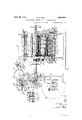
- Figure 1 is a. view in side elevationof a paper ruling, cutting and folding machine.
- Figure 2 is a view in end elevation of vthe paper ruling, cutting and folding machine shewn in Figure l. n
- Figure 2n is a view in sectional elevation of a constructio'nal detail taken on'the dotted line 2?---2a of Figure 2.
- V 4
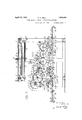
- Figure 3 is a view in longitudinal section on the line 3 3 of Figure 2.
- Vwith the Figure 4 is a view in end elevation ⁇ of paper collecting cutting and delivery cylinders.
- Figure 5 is a sectional plan of the cylinders shewn in Figure 4.
- vj Figure 6 is a plan view of a detail ofthe inr vention.
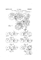
- Figure 7 is a'diagrammatical view of paper'collecting, cutting and delivery cyl# inders, and mechanism governing the actions thereof.
- y F igures-S, 9, 10, 11 and L12 are diagrammatical views illustrating the sequence of ⁇ operations, in the formation of a folded ⁇ book section.
- Figure 13 is a diagrammatical view illustrating the actions'of the collecting cylinder in assembling paper sheets to be subsequently folded to form a book section.
- the numeral ll designates a bed Vplate havingV fixed thereto upright frames 2, spaced apart, in' parallel positions and secured and braced together by a required number of transverse members 3.
- a main shaft 6 which may be provided with a hand-wheel 7, and with fast and loose pul-v leys 8 and 9 or withother suitable driving means or gear.
- a pinion 14 Fixed adjacently to the gear 12, but on the inner side of the upright france2, is a pinion 14 which meshes with a gear 15 carried on an adjustable swinging arm 16 mounted concentrically with respect to the shaft' 13.
- the adjustable swinging arm 16 is'provi'ded with a bolt 17"which'passesthrough an arcuate slot 18 in the upright frame 2,1and the said arm may be secured in adjusted positions, for purposes which will"pre's ⁇ ently appear, by tightening a nut 19 onthe bolt 17,
- agear 20 On the end of the shaftv 13 remote from the adjustable arm 16 is agear 20 which" meshes with van equal gear 21v carriedl onlaV shaft 22 positionedin parallelv alignment,
- an' idler gear 28 which engages a gear 29 on' a'transverse shaft30 rotatively. supported in opi posits frames 2.
- The' shaft 22 is mounted. in bearings'25 carried on slides or plungers 26, which under the laction of springs 27 cause theroll 24 ⁇ to resiliently bear upon the roll 23 preciselyas above described.
- the idler gear' 28 is enfA gaged with and driven Vby the gear l15 whenthe swinging arm 16 is xed in its upper po-l' sition as shewnin Figure 1, butisthrown out of action when the said armis clamped by the nut19 in its lower position asin Figure 3.
- brackets 31 ixed lto the mem; bers 4 is'a reel or roll ofpaper 32 of required width, from which the web ofpaper is drawn by one or other pair ofserrated drawing rolls 23and24.
- a spindle 33, whereon thereel of lpaper 32 is mounted is provided with an adjustable friction brake 34 of usual construction, 'hav-- ing a handle 35 and screwed shaft 36 by means of which the vfriction brake 3 4 and spindle 33 may be adjusted in an endwise direction, to locate the reel 32 in required position.
- the friction brake 34 niayrbe adjusted ⁇ to provide a required tension in the web ofA paper, and thev resiliently'mounted guide roller 37, functionsv as a yieldable resistance to absorb any lsudden variations yof tension orY shocks in the paper'web.
- the web passes from the guidek roller'3'7' ⁇ to and aroundfa guide ⁇ roller 4 1 thence to primary ruling means having a rubber covered impressionroller 4:2, rubbered duct roller43 rotating in a trough 44"of ruling ink,
- the ruling discs 45 convey inl from, the duct roller 43 to the paper vvebrpassing around l the impressionv roller: 42, VVand thereby rule 43,1 the thickness ofthe film of ink maybe v regulated, as required.-
- the spindley48 of the said roller is adapted for endwise adjustment, and for this purpose may be provided with a pair of collars 48,, Figure 2a, engageable by a yolre 4 8b carried between colla-rs 49a on a' threaded shaft 49b having a knurledhead 49 by means of which itmay be screwed-intoV orout of a tapped hole in ,the framing.
- the ruling discs 45 are mounted at required spaced intervals onl aspindle 50 carried-1n bearings 51 V-in the framing of. the ruling means, yand the; spindle 50 may be. providedV with .a central bearing51' carried on an adjustable arm V52 mounted on one of rthe stays 5.
- the first or primary ruling mea-ns is driven biythe main shaft 6, and for Vthis purpose a s ew gear V53 Aon saidv shaft ⁇ meshes with-a v paper and inclined at angles of 45o thereto.
- Thesecondary ruling means is adapted to rule the lother side of the web of paper and constructed similarly to the primary ruling means, and is provided.:withv an in'ipression ⁇ roller 42, duct roller 43, trough 44, ruling discs 45, wiper 46, means Qfor endw'ise adjustment of the duct roller 43 operated by handle 49, and central bearing-51, vcarried by thei adjustable arm 52 ⁇ mountefd on astay 5.
- a gear '5 9 on the impressionroller shaft 58 drives, by means of an idler 60, the gear 6l on the spindle 48 of thedulct roller- 43, in
- the said slittingmeans comprises rotary shears, one cutting member thereof consisting of aperiphery-blade positioned at or about the mid-length of. a roller 66 carried on a shaft y67, rotatively mounted in the opposite members 4.
- the other cutting member comprises a circular blade 68 carried on an arm 69 mounted on oneof the saidstays 5.
- the circular blade 68 enters anarrow peripheral slot .70 in the roller 66andco ⁇ acting Withv the peripheral. blade divides the paper web into two portions of equall width as above mentioned.
- the two equal Y'paper strips or'ribbons pass from the rotary shears tov a rollery 73, which directs'them to a pair of inclined turning bars 74'and ⁇ 7 5 .positioned accurately atright angles to each other and located on opposite sides of the vcentral longitudinal slit inthe accordingly can be adjusted angula-rly with' respect-'to the line of division of the paper ribbons or strips and also to the bar 75,.
- the upper bar 75 forms one side of Yan adjustable triangular frame, the other sides of which consists of a. cylindrical bar 77, and a fiat bar 78.' Y v A
- the bar 77 is atone end slidably mounted in one of the upright frames2, and is provided at its opposite end with a'threaded extension 79 which passes through a correspondingly screwed sleeve '80..rotatively mounted y in the rvframe 2.
- the sleeve 80 is fixed against end movement inthe frame 2, so that when it is rotated the bar 77 will be moved in an endwise direction.
- the bar 78 is A-Xed securelyand at right angles to the bar 77 and the former bar is prop CII vided with a longitudinal slot 81-'at or near its outer end.
- f y l One end of the upper turning bar 75 is adjustably bolted to the slotted end of thebar 78, whereas the opposite end of bar-7 5 is likewise adjustably secured to the bar 77 by abolt passing through a slot 82 in the latter.
- the sleeve 8O is provided with a handwh'eel- 83, by means of which it maybe turned to move the bar 77,-and accordingly adjust the position of the frame consisting ofthe three bars 75, 77 and 78.
- a support 76 is fixed'to the frame 2, near the end of the fiat bar-78 which is provided with a transverse lslot84 through whicha bolt passes intoa hole in the support 76.
- said frame may be fixed in an adjusted-position by tightening the bolt passing through the transverse slot 84'.
- the inclined bars 74 and 75 turn the kpaper strips or ribbons at right angles to their original course'and cause the same. to travel in opposite direction towards the ends of the frames 2 to guide rollers 85 mounted there-
- the paper strips or ribbons pass around the guide rollers 85 and return. towards the cen- 'ral plane of the machine, the strip turned aside by the lower bar 74 passing over agiiide roller 86, and becoming positioned above the strip diverted by the upper -bar 75, as shewn in Figure l.
- the lowergstrip, Figure 1 By adjustment of the bar 75 by the hand wheel 83, the lowergstrip, Figure 1, mayl be positioned exactly over the upper strip, without any overlapping of the edgesof the said strips, and the lines ruled onthe respective.
- Tlie cylinders 87, 88 andv 89 shewn clearly apart from the machine in ⁇ Figures ⁇ 4 and 5, are of approximately the same diameter and are' hollow inconstruction, and are freely mounted on shafts 90, which extend axially through them and are supported by andfixe'd securely in tlicsaid frames 2.
- aiid 89 are parallel 'and lie" in thesaine horizontal plane, and the 'said cylinders are linter-v connected by equal inter-meshing'spur gears 91, thaty isv spur gears having equal numbers of teeth, sothatthe said three cylinders arej thereby constrained to rotate at equal speeds.
- y ln orderfthat bool; sectionsfof two differ-y ent sizes may be manufactured, as previous-l ly mentioned, two setsofcylinders 87, 88 and 89 are provided, although forl some ⁇ purposes machines maybe made .having a' single set' offsaid cylinders only. ⁇ e n
- the machine accordingly may be provided with two sets of cylinders, 87, 88and 89, one
- Either set of cylinders may be OperatedgiV the larger set being drivenwhen the adjustable swinging arm 16 is clampedby the nut 19 Vin the uppergposition,shewny in, Figure l.v
- the gear l5 ismeshed with and rotates the gear-28 and the latter, which at ⁇ alltimes engages the gear 91 ofthe collecting cylinder 87, drives tliefsame andthe cylinders 88 and 89 inter-gearedtherewith.l
- the kperipheries of the adjoining 87 and.88, and 88 and 89, are rspaced at short intervals apart, and, althoughthejsaid:adjoining cylinders rotate oppo'sitely, their peripheries move past each otherin the same direction, as will be readily understood.
- a f y'Attention' beingi directed moreiparticularly to' Fifgures'ft and 5, the collecting cylinder 87 Y 2Q', is* providedl with.; ais/haft '92," hereinafterI termed tire-needle sli-aft, Which isjournaled inHbearings-atopposite 'ends of the said cylinder'and is parallel tothe supporting shaft 90 thereof, and the shaft 92 yro'tatesvvitlr the 25 cylinderand-niovesin a'cir'cular'orbit about theshaft 190, l Y Y Y Theneedleshaft 92"projectsfrom one'end of the-cylinder'87 and is provided vwith an armA 93 having rotativelyl irfounted upon a ⁇ pin 94V ling gherein after described.'
- guide rod 1102" pro'videmeans for adj ustf ⁇ i ing thepositioiis” 'of' thev arm 93, and, c'ain l rib-ller carried thereby, and also permitithe extent? to Which'the needles' 100 projeotvfroin ⁇ j thefcyliuder87 to be 'adjusted as'required..
- the needlesV ⁇ 100 maybe Withd'rawn'oiice and maintained-'beneath theH perlphery.o'fthecylinder 87 for a-portion of each revolution depending uponthe periph- 63 eral exten'toffthe cam*I 96.- However', for purposes hereinafterdescr'ibed, the cani 96 may be removed from the path of the ro'll'er 95, for
- Thev collecting "cylinder 87 also carries a rubber pad 107 which projects somewhat A from the'periphery of the cylinder and ex- 75 tends across the face thereof, andis positioned adjacently to the row offneedl'es 100, but ⁇ is' fixed in advance thereof'in the direction of rotation of the said cylinder.
- a longitudinal opening or gap- 108 is made:n in the periphery of the collecting cylinder'87 in advance of the rubber pad 107, and in the said opening orga'p 108is/positioned a clamping plate 109, which byset screws 110, or the' like, irmlv secures the rubber-pad 107 in po- ⁇ sition.
- The-'clampingplate i109- ' is' provided' with a longitudinal groove'lll, and is'th'ereby fur# nished With'a l'ange'orflip v112, theV purpose y of which will hereinafter appear; 99
- Thetucking blade' 113 may be adjusted to project to a greater or less-distance from the periphery of the cylinder 87 by rotary adjustmentof the lshaft115-r f
- the shaft 115 projects from the'endof the Cylinder: 87 and is provided with a' plate '118 havin'g therein an arcuate'slot v119 through which extendsa bolt'or stud 120, fixed in the efndof the cylinder',
- the arcuate slot/119 permits th'e shaft' 115 tobe rotatedto a limited extent to adjust the tucking' blade' k113 iand Y the saidshaft and blade may be secured in an; 11 adjusted position by tightening a nut 121 on the bolt or'stud 120.
- the cutting cylinder 88 is likewise' provided With a tuc ring blade 113 similariin.alll respects tothat'above'described and mounted on the collecting'cylinder 87'.
- the cutting cylinder 88 and the delivery cylinderv 89 are provided xvithgrippers-'fof' similar' construction, having ra'ixed jaw 1'22 ⁇ ancl-a-movable'jaw 123.
- the fixed jaw V122 comprises a plate fixed by screws 124 to the side of a longitudinalopeningor gap formed inthe periphery of each ofthe cylinders 88v and 89, and the movable jaw 123 ⁇ likewise consists' of' a plate'fixed A1C? iii;-
- Rods'12'7 passing through holesin the plates comprising the said lixed and lmovable' D. jaws, are screwedinto the side ot the said opening or gap, and springs 128 carried on the rods 127 are interposed ⁇ between the movable aw 123 andnuts 129 on the 'outer ends ot theV said rods.
- i j f y The -nnts 129 form abutments ⁇ for the springs 128, and the latter bear -uponthe movable jaw or plate123'and normally hold t-lie samein contact with the ⁇ fixed jaw 122', thereby maintaining the saidjaws in closed position.
- each ofthe shafts 126 project Jfrom the cylinders 88 and 89, and carry arms 130 having at their outer ends rotatable rollers 131, which impinge upon and ride over cams 132 andl 132 respectively, Figures 1 and 7, once during cach revolution of the said cylinders.
- the cam 132 hereinafter more'fully described, is of lined peripheral length in the case of the cylinder 89, but the cam 132 in the case of the cylinders 88 is capable of peripheral extension.
- v The points of impact and departure of the roller or runner 131 with and from the cam 132 and accordingly the time and extent of the opening vot' the A,said grippers, may be varied by peripherally adjusting the position on the shaft 126 et the arm 130.
- the blade 136 is mounted between abut ⁇ ment blocks or chicken woods 137 ,and the said blade and abutment blocks are mounted in a. holder comprising an angle, plate 138 having unequal sides, and a flat plate 139,
- the shaft126 is provided rllhe cylinder 88 is provided with a serrated or saw tooth blade 136, rwhich is positioned. diametrically opposite the gripping jaws 122 and 123 and projects at all times a pread ⁇ secured tothe angle plate 138 lbyg-arrow of Y order to permit ot the radialwadjustmentof Ythe *saidkk blade, thek saine. is provided slots 144 through which the screws lflQeXf.
- the needles 100 again pierce the ends of the entering paper j strips.
- a transverse shaft 147 termed c the camshaft, to which is secured a spur gear 148 similar to those inter-connecting the said three cylinders 87 ⁇ 88 and 89.
- the spur gear 148 isconveniently meshed with the spur'r gear 91 of the collecting cylinder 87, so. that the cam shaft 147 rotates at the-same speed as the said three cylinders 87, 88 and 89, and re-j volves oppositely to the collecting cylinder 87.
- a lever 15'0 Pivoted on a pin 149 fixed in one of the frames 2 ⁇ is a lever 15'0, hereinafterL termed the tripping' lever, one end of4 which has secured to it the'cam 96, previously referred to, which operates the roller on the arm 93,'todraw other part 152 ismovable or angularly ad?-L justable about the said shaft, and is mounted: on a 4lateral extension or boss153-of the fixedl part 151of the cam.- Y Y
- the peripheries ofgtheisaid fixed and mgoveA ⁇ l able paits151-and 152 arel of equal radius, and in-eflect the said parts form a single,V
- cani- 132 the arc of contact of which with the roller or runner131 may be increased or di ⁇ minished by angular adjustment of the mov-y able part 152.
- the movab-le part 152 is provided Awithan arm 154, to a pin 155 in the outer lend of which is attached a link 156.
- the opposite end of the link 156 is extended through a swivelling i lug 157 mounted at the endof the tripping, lever 150, and the link 156 isadjustably se-Y cured by nuts 158 to the said lug.
- a rod 161 Attached to a pin 1:59 ina lug V160 on the trippinglever 150is a rod 161, the opposite end of which passes'through a swivelling lugvv 162 mounted in the frame 2.
- the lug 162 formsv an abutment for the .i
- the cam 96 is maintained in the path of the roller 95 to withdraw ,the needles 100, andthe movable part 152 ofthe cam 132, ⁇ is held in its normal position, wherein .it permits the aw.v 123 to close to make the primary fold, as abovel described.
- a tripping cam or ,eccentric 166 Fixed to the cam shaft 147 is a tripping cam or ,eccentric 166, adapted to Contact .with
- the tripping lever 150 when thus ldis'- placed by the tripping cam 166, is inovedinto a position wherein it holds the needle actuating cam 96 clear of the roller 95, so that the needles 100 are not withdrawn during the revolution of the cylinder 87. lioreover, in theVr position of the tripping lever 150, shewn by armA 154,7and the movable p ⁇ art'152 of the two part cam 132 has been thereby moved into a ybroken lines, the link 156v has displaced theL retardedv position, likewise indicated by 'broken lines.
- the tripping arm-171 under the action.
- a spring 172 preferably arranged asl atorsion spring uponthe said shaft is adapted'tobecome positioned under van abutment' block or tripping piece 173 formedon the tripping lever 150 or fixed thereto, when the lever 150 is elevated by contact of thetrippingcam 1.66vwith the roller 167.
- Thetripping arm 171 when its end is posi-l tionedunder the tripping piece 173 maintainsv the tripping lever 150, in -the idle positionV shewn by broken lines in Figure 7, wherein r as yabove described, the needle actuating cam 96 occupies an idle positiomandthe movable part 152 of rthe said twopart cam is moved into a retarded position wherein it delays the closing of the grippers on the cylinder 88.
- the beater 17 l is adapted to enter the opening or Y gap 1Q8, as the former 'and the latter more past each other during the rotation 'of' thecam shalft 14:7 and the cylinder 87 ,and the cut' or tiailing'ends ⁇ of the collected sheets Cylinders-87mm 88;? i x ⁇ When the trippingleverlOisheld in'its idle position by engagement of the tripping' itt-1115171' with' the tripping Y piece 178, the
- Thesaiclsheets are then-'carried awayby the. closed gripping jaws 122 and 123 and are thereaftertransferred to the delivery cylinder 89,'and refolded precisely in the manner aber@ .lescriloe Y j Y. i
- the collecting ⁇ cylinder 87 may malie a suvlicient number oty Yrev olutims to collectarequired quantity of pairs ⁇ of sheets.
- tlie'trigger 1710l is actuatedvto release the tripping 'arm 171lrom the tripping piece 173
- a counting ratchet 176 and operating ⁇
- the pawl 177 is carried on a-swinging-arm 180/'pivotallyisupported on rspring 186 applies resilient 'outer washer 185 4and.
- the spring 186 setsup frictionhll resistance or vbraking actionopposin-g thef moyement of ratchet disc 178, sorthat the saine willl cease tol move immediately the pawl v17 7 starts upon its idle stroke, and 'said' disc will -reni'ainf stationaryruntihthe said pawl engages the l succeeding notch.
- holes 188 aref made. therein atl-dition- Y ent radial distances from theipivotal-axis'f thereof, and 'the' Iinkorpitman' 182 may be conneet'ed'to' oneor ⁇ otherfof the holes 188 by swinging arm 180'may vbe increased 0r--dij minisheclfandl they stroke ⁇ ofV the IpaWl" 177y ⁇ correspondiiig-ly variedy to rotate the ratchet disc 178 througha 'greater or less distance..
- v Tho-trigger 17()VA isfmounted adjaoently'- to thev ratchet disc17'8, and when thetripping arm 171 isengaged -with'thetmpping piece: 17 3, the vtrigger 170 is positioned in thefpath of the tripping pins 1,91*,and when strucky by one or other of thefsame is moved'to release the ztripping arm'll71 froml the said tripping piece.
- Trippingpins 191 maybe inserted intotwo diametricallyopposed holes 190, orinto all tournoi the same,"andin the latter case ⁇ for a givenl stroke ot-theY swinging varm 180, :the trigger V170 ywill be operated twice as many timesaineach revolution'of the ratchet dise 178 asin theformer casei- Assuming two oppositely disposed pins 191 to have been iixedvin' the. ratchet disc 178.: the pine 1891connecting-the pit'man1182zto theA swingingarm 180may be inserted into one?.
- the cylinder 87 has ro ⁇ tated through a sulicientnu'mber of revolutions toV take up 'a required number of paper sheets, one of the pins y191,strikesupon the trigger ⁇ 170, and thereby releases the-tripping arm "171, i-n this way permitting the tripping ⁇ r lever 150 to placetliec'am 96 in its operative position to withdraw the needles 100, and. ⁇
- the movablepart V152.0f the cam 132 in its normal position, wherein it allows-the ⁇ grip- ⁇ pers of the cylinder 88 to close upon the tucking blade 113 of the cylinder 87 -toffold the with the trippingpiece 173 until the following pin 191 strikes upon the trigger 17 Orand releases the tripping arm 171.
- the trigger 170 willbe operated at: regular' intervals more frequently, andbyfappropriate connection ofthe pitman f1824-to' ⁇ oneof theholes 188 of the swinging arm 180, the trigger 17 0 maybe actuated to release the tripping lever after two, three, or four revolutions .of the cam shaft 147 and collecting cylinder87, and accordinglyvafter four,
- Theratchet disc k178 may, foreXamp-le,havey sixty equally spaced notches 181 formed in' its periphery and adapted forengagement with the pawl 177 and if the'l pawl'177 is adapted by suitable connectiony of the pitman 1,82 to the swinging arm 180, to move freely over Vten notches 181 it will at the commencement of its return movement engage the-'tenth notch 181fto yrotate thel said disc.
- the pawl 177v will completely rotate the ratchet disc fonce 'in eVery.siX revolutions of: ⁇ the camshaft andcylinder 87 gearedtherewith.
- the ratchetV disc 178 will be rotated once inv every live revolutions of the A camv shaft 147 '-93 and collectingcylinder 87g4 Againfif .th
- theratchetdisc 178 will be rotated onceffin every 'four revolutions lof 'the said cam andcylinder.
- 'I l yAccordingly-,it will be understoodgthat byusingthe vappropriate numberof pins 191y initherratchetdisc 17 8 to release the', trigger 170, and suitably adjusting the connection ofvv the pitmanff182 to the holes 188 of the-swinging arm 180,'four, six, eight or moresheets maybe collected by the cylinderV 87before ⁇ 1 thetrigger is operatedby one or other of the pins 191 torelease the tripping armk 1-71, and vthereby permitthek collected sheets tobe folded 4by the co-action of the tucking blade on the cylinder 87 and the grippers on the cylindery 88, f and to be taken- ⁇ byl the' said-grippers away from the former cylinder.
- the periphery of the delivery cylinder 89 is provide'dzwith aseries ofgrooves' 195 into y eachof ,which extends astripper blade'196 as shewn in Figure
- The-ends of the stripper blades 1196 are located within the periphery
- Thestripper blades 196k removeeach folded book section from the delivery cylinder 89,v
- the lstripper blades 196 co-operate with guidestrips197-toform a tapered conduit'to' receivethebook sections from the cylinder f'llhe: gear-202 engages and operatesVA aggear:
- the delivery belts 211 mover overtlie up Y perfsnrfacefo la platform or,l Vtable k221, r supf portedbythe projecting bars 218-.
- the shaft' 220 is' Journaled 1nv the frames 2, and oneend thereof extends--throughfone ofthe-frames 2 and'fhas fixed to zit a ratchet disc i 222, ishewn clearlylinFigiire n ⁇ Rotatively ⁇ mounted in andtransversel'y Vto y tlieframes'2 and one end extended in proximity "to they ratchety disc 222 is.
- a shaft 22,hw llgfixed toits YprojectingV endiany arm' which is connected by apitrnan- 225 to a sereine Moimted s on a pinf22 in.
- Y extension; 229 c )fytbfe arm.. 224;j is Vaf.piemel 230 adapted to engagethe teethoizthe ratchet dise -222gtofrotate the same.
- An improved machine for the manufacture of folded book sections as claimed in claim 3 having Ltwoindependent sets ofv the sa-i'd collecting, cutting and foldingy mecha-y nism to cut from the said contiguous paper strips sheets differing in length 'and'r to fold the' same to form dissimilar book sections, two groups of traction means, counting mechanism and means for delivering the same, one of the said groups being operatively connected and cop-acting with one set of the saidv collecting cutting and folding mechanism and the second group being similarly associated with the other set of the said mechanism, and driving means adjustably engageable with either of the said sets to actuate the same and the corresponding group connected therewith.
- a machine for the manufacture of folded book sections as claimed in claim 3, hav# ing two independent sets of collecting, ⁇ cutting, folding and counting mechanisms, a gear train to operate the said sets of cutting' and folding mechanism and associated groups of counting mechanism, a swinging ⁇ arm in the gear train, a gear on the swinging arm engageable by adjustment of the said arm with either a gear operating one of the said sets and groups or an idler actuating the other set and group, and means for fixing the said 6.
- a machine for the manufacture of book sections having means for cutting a pair of sheets from the contiguous paper strips and for doubly folding the same, comprising a cylinder of a series of three intergeared and interacting cylinders, equal interme-shmg gears on the three cylinders operatively congolnecting the same, a spring extending the needles from the periphery of the said cylinder to pierce the ends of the paper strips, a shaft mounted in the said cylinder and operatively connected with the needles, an arm Vfixed to the shaft, a roller on the shaft, a j
- a pivotedtripping Vlever having the ,needle withdrawing cam on one end, avlink connect-. ing the opposite end of the said lever tothe" arm on the adjustableL portion of thefexpansible cam, a spring maintaining the tripping lever inits active positionwherein the needle j 12oY i camshaft to displace thev said lever and r'e-y move the needle withdrawing cam from its operative position and angularly move the adjustable portion of the Isaid expansible cam, i
- counting means comprising a tripping lever, associatedA 'with the collecting mechanism, a
- countingy means comprising Y a tripping ,lever f associated With thecollecting mechanism, a
- trippingpiece on the'tripping lever a tripping arm to engage.
- the tripping piece a shat't adjacent to the tripping-lever, a ratchet disc onthe shaft, notches in the periphery of the ratchetv disc, an oscillatable armfpivotally ⁇ supported on the shaft, a crank discon a cam shaft, a crank pin in the crank disc, a pitman connecting the oscillatable Y l tol ythe crank pin, a pavvl on the oscillatable arm'engageable with thenotches in the ratchet dise to intermittently: frotatef the same,V ⁇ Y braking means opposing the movement ofthe-ratchet 270 tent of the arc of oscillation of the said arm and the ⁇ travelrofthe pawl, ⁇ notches inthe Vperiphery/,of :the saiddiscfengageable with the vpavvl. and corresponding'toathe Vdifferent arc'sof
- J means for preventing re-cutting .or :clipping .of 'the severedsheets carried by a cylinder embodied in the collecting'inechanism, -comprising'a longitudinal opening inthe collecting cylinder, va lip extending along the said-opening, and a'tail beater to force the entends of the sheets into the opening and vbehind the said li i Y pIn witness whereof I hereunto aix 'my signature.
Description
W. R. BELL April l2, 1932.
PAPER RULING, CUTTING, AND FOLDING MACHINE'Y 5 Sheets-Sheet l Filed Aug. 20, 1930 `IlllIHlllillll lllllllllllllfll I MAS.
om R. .W
April 12, 1.932.
W. R; BELL PPER RULING, CUTTING, AND FOLDING MACHINE Filed Aug. 20, 1930 5 Sheets-Sheet 2 lw N, NM
April 12, 1932.`
W. R. BELL PAPIERl RULING, CUTTING, AND FOLDING MACHINE Filed Aug. 20, 1930 5 Sheets-Sheet 3 W. R. BELL April. 12, 1932.
PAPER RULING,/CUTTII\I.G, AND FOLDING MACHINE Filed Aug.. 2o, 1930 5 She'ets-Sheet 4 num-"Th1- n y `llllilll l Il Il lll!!! April 12, 1932. W. R. BELL 1,853,494
` PAPER RULING, CUTTING, AND FOLDING MACHINE Filed Aug. 20, 1930 5 Sheets-Sheet 5 Ey' l yf.
Patented Apr. 12, 1932 Unirse STATES WILLIAM. RUSSELL BELL, OF SOUTHl IiIELBOURNE, VICTORIA, AUSTRALIA, ASSIGNOR- TO BELL & VALENTINE PROPRIETARY LIMITEDVyOF SOUTH MELBOURNE, VICTORIA.,
'AUSTRALIA ,is
PAPER nutrire, CUTTING, A-NnroLDiNe Mirc'nmn Application flied-August "2o, i930, seriaifNo. Meest, and nieren: Briiaindseptemter y2, 1929.
rhis invention relates to improvements in y cutting, and folding are automatically performed, in required sequence on a web of paper drawn from a reel or roll mounted on the machine or positioned adja'centlyA thereto, to produce completed book sections having predetermined numbers of liiages.'A
' In the present invention the webof paper is' drawn from the reel or roll by means of e one or more co-acting pairs of inter-geared serrated drawing or Vtraction rolls, and is firstly ruled on one or both sides. After being ruled, as required, the web ofpaper is.
cut or divided longitudinally into two strips or ribbons of equal width, each strip or ribbon being, accordingly, half the width of the reel or roll. :4 n
rlhe separated ribbonsor` strips are nextcaused to vmove in opposite directions andi at right angies to their original course, and afterV passing around suitable guiding members,
approach each other and move `into contact and finally become superposed one upon the other, and said strips or ribbons,A with their correspondingly ruledlines accurately reg- V istered then travel in the same direction.
The superposed strips or ribbons are now' by and caught upon a series or row of needles or spikes projecting from the periphery of the collecting cylinder.
The piercing needles carry within the said periphery to-release the ends of the paper strips.
sections, whereby'the operations of ruling,
the ends of the* strips or ribbons a predetermined distancev around the periphery of the :collecting cyl-v inder, w iereupon the, needles are withdrawn vt or about the time the needles release the paper strips, 'a tucking blade,'carriedfby the collecting cylinder, venters between open grip# ping jaws, or 'shortly grippers, mounted on the cutting cylinder, aiidpushing laterally on the,superposed'l paper stripsimpels the sanieinto .tlievsaid gripp'ers which close over the ltucking v,blade and the portion of said strips therein. y Y i e The relative movement ofthe collecting andcutting cylinders'causes the tucking blade to slide outwardly from saidgr'ippers which` closing firmly" upon the ypaperfst'ripsfold. thesame. rlhe `said cylinders :have now" revolved approximately through` one half arevolution from the positions they' occupied when the needles pierced the paper strips. Upon fur,-A ther rotation the grippers paper strips around the periphery of the cutting cylinder and draw the yreleased ends of the said strips backwardly from vthe collecting cylinder. o
The folded portion of the paper strips or ribbons are ystillcon'nected with the reel or roll, and said strips or ribbonsl continue to pass between the collecting and cuttingcylin# ders and are maintained taut by the traction of the gripping jaws or grippers. `However, at the vcompletion of approximately a further half revolution and rather less than one revolution from the original point-'atwhich kthe needles penetrated the superposed paper strips, a. cutting blade on the cutting cylinder coacts with 'arubber pad on the collecting cylinder to sever the folded portions from the said paper strips.
' Theperipheral length of the cutting cylin-` der is made approximately fourtimes the width of the required exercise bookand acy cordingly at this stage a book section having four leaves of twice the lrequired width isy obtained. 1t, therefore, becomes necessary to,4 fold the section again to make it of stand-` ard'width. r A f f,
For this purpose, and whenk the said grip; pers have carriedthe section a sufficient distancev around'the periphery of the cutting f1 cylinder, a tucking blade thereon 'bears lat-' erally on the section at 'approximately the draw the folded y A mid-width thereof and inserts the paper leaves between similar spring closed gripping jaws or grippers on the delivery cylinder and re-foldsthe section to approximately Standard width in the manner -above described. `At or about the Vsame time the grippersl on the cutting cylinder open and release the previous or first fold of the section.
, The sectionv now held bythegrippers of the delivery cylinder Viscarried away from the cutting cylinder and said jaws are opened to release the section when the same has been positioned under propelling rolls... The section is finally removed from the delivery cylinder by strippers-and Vguided thereby to nipping or squeezing rolls which compress and fold', it more,tightlyuanddeposit it on interdescribed and so on continuously. Y
niittently propelled delivery belts, n i Immediately after thev folded section is severed bythe interactionof nthe said cutting blade and rubber pad,f the needles again pierce thesuperposed paper "stripsandl a further'section is produced in themanner ab'ov The successive sections are Athrown forwardly by beatersv on to the intermittently propelled delivery'belts and the said sections are thereby delivered in overlapped fan formation; i 'A Y y kBook sectionsconsisting of the two sheets l' offpaper severedV from the4 superposed strips oriribb'ons at` each revolution of the cutting andcollecting cylinders, andformedas above described, will,V when ruled in accordance with thestanda'rd system of ruling, bind into exercise books'having sixteen pages. 1
Anim ortant featureof the present invention resi es inthe provision of special counting and tripping mechanism whereby the needles carried by the collecting cylinder, in-
stead of receding within the periphery of the l.said cylinder during each revolution tliercohaie maintained in an operative position wherein they Aproject from the periphery of the collecting cylinder for two, three, four or more revolutions. Moreover, by means of thesaid counting and trippingmechanism, the closing of the grippers on the cutting cylin'derfis simultaneously delayed, so vthat al-V though-the tucking blade exerts lateral pressureon )the superposed paper strips and pushes thei'same intothe openJgrippers at each revolution, no fold is made, since the grippersdonot close Vand the paperstrips or ribbonsare merely diverted into and pass out of the same.
Meanwhile, the said counting andL tripping mechanism does not affect the normal opera- Vtion ofthe `cutting blade on the cutting cylin-A der, kand the rubber pad coacting therewith onrthe collecting.Y cylinder; accordingly, the sheets, or portions of the superposed paper stripsfor ribbons taken up by theneedles and woundarround the periphery ='of the collecting cylinder ate'ach revolution are cut away from mation on the vdelivery belts.
Vently I The folded sheets are then transferred by the Igrippers to thedelivery cylinder and,
after being again folded in themanner above outlined, are deposited in overla pecl fan forn this manner, by allowing the needles to remain in their operative positions during two revolutions, four paper sheetswill be wound u on Y thecollecting cylindenand said sheets W len folded and delivered, as above mentioned, will form book sectionsV having thirty-two pages. VVSimilarly,
,by permitting Ypaper e sheets' to mount upon thevcollecting cylinder for. three revolutions, corresponding book scctionshaving forty-eight pages willbe produced, and so on, sixteen extra pages being formed inthe book i sections for each additional revolution ofthefcollecting cylinder.
Another feature. of the invention resides inA the; provision of means whereby the rear or trailing ends ofeach pair of sheets afterthe same have been cut from the superposed strips or ribbons, are impelled'into a longitudinal gap in the collecting cylinder and maintained therein durlng'subsequent revolutions of the` collecting cylinder and until the needles thereon are withdrawn .and the grippers on the cutting .cylinder are closed by the action of the counting and tripping mechanism.
By this means the rear or trailing ends of the cut or severed sheets are maintained wit inthe said gap in a position wherein they cannot be clipped or re-cut during the succeeding revolutions of the collecting and cutting cylinders, and they remain in this positionluntil they are withdrawn from the co1- lecting cylinder by the grippers on the cut-- ting cylinder.k l A further feature of the invention consists 1n the mounting on the machine of independoperated cutting and folding mechamsm, adapted to manufacture two different standard sizes of exercise books. For this purpose' twosimilar sets of intergeared col-- lecting, cutting, and delivery cylinders are provided, the three cylinders of each set having approximately the same diameter, but the respective diameters of the cylinders of the two sets being unequal and suited to the sizes of the two different standard exercise books. Adjustable driving. means are provided, whereby one or theotherset of cylinlrl O ders may lue-operatively connected main sha-ft of the machine. Y
In the drawings illustrating the Ainvention: f v
Figure 1 is a. view in side elevationof a paper ruling, cutting and folding machine. Figure 2 is a view in end elevation of vthe paper ruling, cutting and folding machine shewn in Figure l. n
Figure 2n is a view in sectional elevation of a constructio'nal detail taken on'the dotted line 2?---2a of Figure 2. V 4
Figure 3 is a view in longitudinal section on the line 3 3 of Figure 2.
Vwith the Figure 4 is a view in end elevation `of paper collecting cutting and delivery cylinders.
Figure 5 is a sectional plan of the cylinders shewn in Figure 4. vj Figure 6 is a plan view of a detail ofthe inr vention. Figure 7 is a'diagrammatical view of paper'collecting, cutting and delivery cyl# inders, and mechanism governing the actions thereof.
y F igures-S, 9, 10, 11 and L12 are diagrammatical views illustrating the sequence of `operations, in the formation of a folded `book section.
Figure 13 is a diagrammatical view illustrating the actions'of the collecting cylinder in assembling paper sheets to be subsequently folded to form a book section.
In these drawings the numeral lldesignates a bed Vplate havingV fixed thereto upright frames 2, spaced apart, in' parallel positions and secured and braced together by a required number of transverse members 3.
Fixed to one of the frames 2, and to the bed plate 1, are similar L-shaped members l,
which are'likewisefirmly secured in parallel positions by transverse bracesY or stays 5.
Mounted in suitable bearings in the frames 2 and on one of the L-shaped members 4:- is a main shaft 6, which may be provided with a hand-wheel 7, and with fast and loose pul-v leys 8 and 9 or withother suitable driving means or gear.
On the main shaft 6 1s a pinion 1() wh1ch lmeshes with an idler gearv 11, engaging Aa gear 12 fixed securely on a shaft 3 extending transversely between the upright frames 2 and rotatively mounted in bearings therein. Fixed adjacently to the gear 12, but on the inner side of the upright france2, is a pinion 14 which meshes with a gear 15 carried on an adjustable swinging arm 16 mounted concentrically with respect to the shaft' 13.
The adjustable swinging arm 16 is'provi'ded with a bolt 17"which'passesthrough an arcuate slot 18 in the upright frame 2,1and the said arm may be secured in adjusted positions, for purposes which will"pre's`ently appear, by tightening a nut 19 onthe bolt 17,
On the end of the shaftv 13 remote from the adjustable arm 16 is agear 20 which" meshes with van equal gear 21v carriedl onlaV shaft 22 positionedin parallelv alignment,
vsiliently bear upon the periphery'of the drawingroll 23` and thereby rmly grip the paper passing between the said drawing rolls.
Mounted onthe upright frame 2is an' idler gear 28which engages a gear 29 on' a'transverse shaft30 rotatively. supported in opi posits frames 2.
' r*lhershaft 30 .operates serrated drawing rolls and 24 similar Vto 'those above" described, of which the roll 23 is mounteduponjy the shaft30, andthe rolll 24C` is mounted'on a shaft 22 parallel to the said shaftj'30, and
` driven bythe same gears"`20 and' 21.: The' shaft 22 is mounted. in bearings'25 carried on slides or plungers 26, which under the laction of springs 27 cause theroll 24`to resiliently bear upon the roll 23 preciselyas above described. The idler gear' 28 is enfA gaged with and driven Vby the gear l15 whenthe swinging arm 16 is xed in its upper po-l' sition as shewnin Figure 1, butisthrown out of action when the said armis clamped by the nut19 in its lower position asinFigure 3.
` Mounted on brackets 31 ixed lto the mem; bers 4 is'a reel or roll ofpaper 32 of required width, from which the web ofpaper is drawn by one or other pair ofserrated drawing rolls 23and24..
A spindle 33, whereon thereel of lpaper 32 is mounted is provided with an adjustable friction brake 34 of usual construction, 'hav-- ing a handle 35 and screwed shaft 36 by means of which the vfriction brake 3 4 and spindle 33 may be adjusted in an endwise direction, to locate the reel 32 in required position.
The paperweb on leaving the reel 3.2 passes around a guide roller 37 mounted on arms 38 of levers, the opposed arms 39V of which are connected to spring plungers 4 0.;
The friction brake 34 niayrbe adjusted `to provide a required tension in the web ofA paper, and thev resiliently'mounted guide roller 37, functionsv as a yieldable resistance to absorb any lsudden variations yof tension orY shocks in the paper'web. f-
The web passes from the guidek roller'3'7'` to and aroundfa guide` roller 4 1 thence to primary ruling means having a rubber covered impressionroller 4:2, rubbered duct roller43 rotating in a trough 44"of ruling ink,
ICS
and ruling discs revolvingin contact with Y a duct roller 43.
The ruling discs 45 convey inl from, the duct roller 43 to the paper vvebrpassing around l the impressionv roller: 42, VVand thereby rule 43,1 the thickness ofthe film of ink maybe v regulated, as required.-
uit.
.v n iorder to prevent ther formation ,of grooves i'n the duct roller 43 at the points of contact of the'rulin'g discs 45 therewith, the spindley48 of the said roller is adapted for endwise adjustment, and for this purpose may be provided with a pair of collars 48,, Figure 2a, engageable by a yolre 4 8b carried between colla-rs 49a on a' threaded shaft 49b having a knurledhead 49 by means of which itmay be screwed-intoV orout of a tapped hole in ,the framing. i Y n I The ruling discs 45 are mounted at required spaced intervals onl aspindle 50 carried-1n bearings 51 V-in the framing of. the ruling means, yand the; spindle 50 may be. providedV with .a central bearing51' carried on an adjustable arm V52 mounted on one of rthe stays 5. The first or primary ruling mea-ns is driven biythe main shaft 6, and for Vthis purpose a s ew gear V53 Aon saidv shaft` meshes with-a v paper and inclined at angles of 45o thereto.
similar'gear54 on a `counter shaft .55. E 1
On the. countershaft 55 is a gear, wheel 56 whichengages with a gear 57 mounted on the shaft 58 of the impression roller 42. Ar gear 59, fixed to the shaft 5.8 meshes with an idler 6D,which in turn.engages with and rotates ,ai gear61 mounted. on the spindle 48 of the duct 4 Y bolted to slotted supports 76, and said bar ro1ler43.Vv
The Web of paper upon being ruledy on one side the primary ruling means passes therefrom `to ay guide roller 62 lmounted on thek framing of secondary ruling means,
thence around guide roller 63, andtherefromto theimpression roller 42 of the said secondary rulingmeans. y
Thesecondary ruling means is adapted to rule the lother side of the web of paper and constructed similarly to the primary ruling means, and is provided.:withv an in'ipression` roller 42, duct roller 43, trough 44, ruling discs 45, wiper 46, means Qfor endw'ise adjustment of the duct roller 43 operated by handle 49, and central bearing-51, vcarried by thei adjustable arm 52`mountefd on astay 5.
` VThe .secondary ruling'means operated by an. idler gearv 64, which inter-connects the`lr gear 56 on thecountershaft 55 withthe gear 57 on the impressionlroller shaft 58. 'l
A gear '5 9 on the impressionroller shaft 58 drives, by means of an idler 60, the gear 6l on the spindle 48 of thedulct roller- 43, in
the same way as in the primary ruling means.
The web of paper, now ruled on one or both sides as required,vpasses from the impression roller 42 of the secondary'V ruling means, to slitting means accurately adjusted to sever or cut the said paper web longitudinally into two equal portionsor halves, thereby'forming two paper stripsor ribbons o1 exactly the same width.
The said slittingmeans, comprises rotary shears, one cutting member thereof consisting of aperiphery-blade positioned at or about the mid-length of. a roller 66 carried on a shaft y67, rotatively mounted in the opposite members 4. The other cutting member comprises a circular blade 68 carried on an arm 69 mounted on oneof the saidstays 5.
The circular blade 68 enters anarrow peripheral slot .70 in the roller 66andco`acting Withv the peripheral. blade divides the paper web into two portions of equall width as above mentioned. f V A norder to operate thesaid rotary shears a gear wheel 71 is mounted .on the shaft 67 and is driven by the gear wheel 57 on the sec- 5,
ondary ruling means by means of an intermeshmg idler gear 72. A f
The two equal Y'paper strips or'ribbons pass from the rotary shears tov a rollery 73, which directs'them to a pair of inclined turning bars 74'and`7 5 .positioned accurately atright angles to each other and located on opposite sides of the vcentral longitudinal slit inthe accordingly can be adjusted angula-rly with' respect-'to the line of division of the paper ribbons or strips and also to the bar 75,.
The upper bar 75 forms one side of Yan adjustable triangular frame, the other sides of which consists of a. cylindrical bar 77, and a fiat bar 78.' Y v A The bar 77 is atone end slidably mounted in one of the upright frames2, and is provided at its opposite end with a'threaded extension 79 which passes through a correspondingly screwed sleeve '80..rotatively mounted y in the rvframe 2. The sleeve 80 is fixed against end movement inthe frame 2, so that when it is rotated the bar 77 will be moved in an endwise direction. v i v The bar 78is A-Xed securelyand at right angles to the bar 77 and the former bar is prop CII vided with a longitudinal slot 81-'at or near its outer end. f y l One end of the upper turning bar 75 is adjustably bolted to the slotted end of thebar 78, whereas the opposite end of bar-7 5 is likewise adjustably secured to the bar 77 by abolt passing through a slot 82 in the latter.
By means of the bolts and slots 81 and82 the inclination of bar 75to the line of division of the paper and to the bar 74 may be adjusted, as necessary. w
The sleeve 8O is provided with a handwh'eel- 83, by means of which it maybe turned to move the bar 77,-and accordingly adjust the position of the frame consisting ofthe three bars 75, 77 and 78.
A support 76 is fixed'to the frame 2, near the end of the fiat bar-78 which is provided with a transverse lslot84 through whicha bolt passes intoa hole in the support 76.
On adjustment of the frame, coiisistingof the bars 75, 77 and 78, by the sleeve 80, the
said frame may be fixed in an adjusted-position by tightening the bolt passing through the transverse slot 84'.
One of the paperV strips or ribbons passes over and partly around the lower turningbar 7 4, ywhereas the other strip or ribbon passes under and partly around the upper turning bar 75.
The inclined bars 74 and 75 turn the kpaper strips or ribbons at right angles to their original course'and cause the same. to travel in opposite direction towards the ends of the frames 2 to guide rollers 85 mounted there- The paper strips or ribbons pass around the guide rollers 85 and return. towards the cen- 'ral plane of the machine, the strip turned aside by the lower bar 74 passing over agiiide roller 86, and becoming positioned above the strip diverted by the upper -bar 75, as shewn in Figure l.
By adjustment of the bar 75 by the hand wheel 83, the lowergstrip, Figure 1, mayl be positioned exactly over the upper strip, without any overlapping of the edgesof the said strips, and the lines ruled onthe respective.
strips may be brought into accurate registration.
The paper strips now accurately aligned and superposed one above the other approach andV pass between either pair of drawing rolls 23 and 24, which have drawn them firstly, as a single web of paper from `the reel or -contact witheach other, are fed to the previously mentioned folding and cutting'mecha-y nism,which as hereinbefore stated primarily comprises a collecting cylinder 87 a cutting cylinder 88, anda deliverycylinder 89.
" Tlie cylinders 87, 88 andv 89 shewn clearly apart from the machine in` Figures`4 and 5, are of approximately the same diameter and are' hollow inconstruction, and are freely mounted on shafts 90, which extend axially through them and are supported by andfixe'd securely in tlicsaid frames 2. i
The shafts 9o of the three eyiinders er, 88-
therewith or respectively. governing the actions thereof, are similar in construction, ar-
rangement, and. operation, but the diameters of the icylinders` of the respective sets are dimensioned to adapttheirLperipheriesto the sizes of the two -different book sections. y
The machine accordingly may be provided with two sets of cylinders, 87, 88and 89, one
set being offconsiderably greater ysize than the other, as shewn in Figures l and 3.
Either set of cylinders may be OperatedgiV the larger set being drivenwhen the adjustable swinging arm 16 is clampedby the nut 19 Vin the uppergposition,shewny in, Figure l.v In this position the gear l5 ismeshed with and rotates the gear-28 and the latter, which at `alltimes engages the gear 91 ofthe collecting cylinder 87, drives tliefsame andthe cylinders 88 and 89 inter-gearedtherewith.l
Similarly, theV cylindersy 87 88"and 89, 'of the smaller set will be operated, when the arm- 16 is adjusted vto mesh the'V gearv-15withthe gear 91 of the collecting cylinderv;87 ofthe said set, as shewn in Figure 8. Y
ioo
- f Thethree cylinders y87, 88 and 89 of each f setA are arranged .in line, the cutting cylinderV 88 of each setabeing positioned betweenthe collecting cylinder 87 and the .delivery cylinder 89 thereof, and thecylinders 87 .and 89. rotate inthe same direction `and oppositely-4 to the Asaidcutting cylinder 88. 1
. The kperipheries of the adjoining 87 and.88, and 88 and 89, are rspaced at short intervals apart, and, althoughthejsaid:adjoining cylinders rotate oppo'sitely, their peripheries move past each otherin the same direction, as will be readily understood.
-The serrated drawing rolls 23 and-24 are positioned above the cylinders'87, 88 and 89,
mathe-paperlsaipsfdeseendffom the Said rolls: between" Vthe collecting cylinder 87 and? thefeuttingcylinder -88fof thefsaid larger set as shevvn inf'Figure 1.' Y
When'. the 'set of smaller cylinders is in operation', the positionsof the paper strips on: entering the drawingrolls 23 and 24 are cable'toeith'er'setof cylinders 87, 88 and 89,-
Ig, for,"as above mentioned, b'othsets and the meeh'anism associatedther'ewith are similar p inffconstru'ctionland operate in' the-saine Way'.
A f y'Attention' beingi directed moreiparticularly to' Fifgures'ft and 5, the collecting cylinder 87 Y 2Q', is* providedl with.; ais/haft '92," hereinafterI termed tire-needle sli-aft, Which isjournaled inHbearings-atopposite 'ends of the said cylinder'and is parallel tothe supporting shaft 90 thereof, and the shaft 92 yro'tatesvvitlr the 25 cylinderand-niovesin a'cir'cular'orbit about theshaft 190, l Y Y Y Theneedleshaft 92"projectsfrom one'end of the-cylinder'87 and is provided vwith an armA 93 having rotativelyl irfounted upon a `pin 94V ling gherein after described.'
Fixefdjto -theneed-leshaft92 Within the cyl- Y y in'deri87, i-saroW ofaligned arn'isr'v 97, the ends' '$5 o'f-vvhielli'are connected Vby pins 98`to plungers` 99, eaclfro'f- Whichf'carries a'needle orv spike -up'onjalshouldei 103 thereon.' The guide rod' 102:r isj attached *conveniently to an `extension 104:1'olfEA thepin and is' yslidablyv fitted in a giu'ide 105 ixed to :the end ofe the 'said cylj djus't-able 'cl'ieckv nuts" 100 screyved upon the? guide rod 1102" pro'videmeans for adj ustf` i ing thepositioiis" 'of' thev arm 93, and, c'ain l rib-ller carried thereby, and also permitithe extent? to Which'the needles' 100 projeotvfroin` j thefcyliuder87 to be 'adjusted as'required..
e roller 95 contacts with the cam 96 at" 155i ai? eertain'p'oilitv in; each revolution of the cylinder? 87- andthe' said cam impels the roller 95 and arm 93 towards the axis of the cylinder,
alidtliereby partly rotates the shaft 92 and draws the needles Within"theperiphery` 60 'f ofthesaid 'eylindera In this' WayA the needlesV` 100 maybe Withd'rawn'oiice and maintained-'beneath theH perlphery.o'fthecylinder 87 for a-portion of each revolution depending uponthe periph- 63 eral exten'toffthe cam*I 96.- However', for purposes hereinafterdescr'ibed, the cani 96 may be removed from the path of the ro'll'er 95, for
one Vor more 'revoll'itions7 offthe cylinderS',
sov that the needles -100 continue to project from thelperipheryf'of the saidcylinder, until such time asthecam'96 is" restored toits operative position. i Y Y Thev collecting "cylinder 87 also carries a rubber pad 107 which projects somewhat A from the'periphery of the cylinder and ex- 75 tends across the face thereof, andis positioned adjacently to the row offneedl'es 100, but `is' fixed in advance thereof'in the direction of rotation of the said cylinder. v
A longitudinal opening or gap- 108 is made:n in the periphery of the collecting cylinder'87 in advance of the rubber pad 107, and in the said opening orga'p 108is/positioned a clamping plate 109, which byset screws 110, or the' like, irmlv secures the rubber-pad 107 in po-` sition. j
The-'clampingplate i109- 'is' provided' with a longitudinal groove'lll, and is'th'ereby fur# nished With'a l'ange'orflip v112, theV purpose y of which will hereinafter appear; 99
Positioned diametrically opposite'to' the rubber pad 107 is'a fixedftuckingjblade 'orl plate 113 'which extends throughf anotherY longitu'clinalopening 1-14 made in the cylinf n der 87, and projects from the periphery-'ofi the said cylinderlat'allvtimes.
, R' tatively'mounted in opposite' ends of the cylinder 87 and extendingtherethrou'gh, is a shaft115 having achordal-surface, or flat; 116 upon which the tucki-ng'blade 113-is firm'- ly secured by screws 117 which pass through the same andlinto'tafpped holes inthe Ishaft 115'." i
Thetucking blade' 113 may be adjusted to project to a greater or less-distance from the periphery of the cylinder 87 by rotary adjustmentof the lshaft115-r f The shaft 115 projects from the'endof the Cylinder: 87 and is provided with a' plate '118 havin'g therein an arcuate'slot v119 through which extendsa bolt'or stud 120, fixed in the efndof the cylinder', The arcuate slot/119 permits th'e shaft' 115 tobe rotatedto a limited extent to adjust the tucking' blade' k113 iand Y the saidshaft and blade may be secured in an; 11 adjusted position by tightening a nut 121 on the bolt or'stud 120.
The cutting cylinder 88 is likewise' provided With a tuc ring blade 113 similariin.alll respects tothat'above'described and mounted on the collecting'cylinder 87'.
The cutting cylinder 88 and the delivery cylinderv 89 are provided xvithgrippers-'fof' similar' construction, having ra'ixed jaw 1'22` ancl-a-movable'jaw 123.
The fixed jaw V122 comprises a plate fixed by screws 124 to the side of a longitudinalopeningor gap formed inthe periphery of each ofthe cylinders 88v and 89, and the movable jaw 123 `likewise consists' of' a plate'fixed A1C? iii;-
byscrews 125 to a flat on a shaft 126V journaled in the ends oi" the said cylinders'.
Rods'12'7, passing through holesin the plates comprising the said lixed and lmovable' D. jaws, are screwedinto the side ot the said opening or gap, and springs 128 carried on the rods 127 are interposed `between the movable aw 123 andnuts 129 on the 'outer ends ot theV said rods. i j f y The -nnts 129 form abutments `for the springs 128, and the latter bear -uponthe movable jaw or plate123'and normally hold t-lie samein contact with the `fixed jaw 122', thereby maintaining the saidjaws in closed position. v ,l 'j
The ends of each ofthe shafts 126 project Jfrom the cylinders 88 and 89, and carry arms 130 having at their outer ends rotatable rollers 131, which impinge upon and ride over cams 132 andl 132 respectively, Figures 1 and 7, once during cach revolution of the said cylinders. The cam 132 hereinafter more'fully described, is of lined peripheral length in the case of the cylinder 89, but the cam 132 in the case of the cylinders 88 is capable of peripheral extension. v
Impact of the roller 131 upon the cam 132, detlects the arm 130 outwardly, and thereby rotates the shaft 126 to move the jaw 123 away from the jaw 122, and the said jaws are maintained in an open position during the passage of the roller 131 over the cani.
vThe points of impact and departure of the roller or runner 131 with and from the cam 132 and accordingly the time and extent of the opening vot' the A,said grippers, may be varied by peripherally adjusting the position on the shaft 126 et the arm 130.
with a fiat or cliordal surface 133 at or near the'opposite ends of `'which set screws 134 Contact er bear. Theset screws 134 are passed,
opening of the movablejaw .123.
justed distance from Vthe periphery of the said cylinder. i n
AFor this purpose, the shaft126,is provided rllhe cylinder 88 is provided with a serrated or saw tooth blade 136, rwhich is positioned. diametrically opposite the gripping jaws 122 and 123 and projects at all times a pread` secured tothe angle plate 138 lbyg-arrow of Y order to permit ot the radialwadjustmentof Ythe *saidkk blade, thek saine. is provided slots 144 through which the screws lflQeXf.
tend.
are likewise provided with slots14l5 through which the screws 1110 gajss, and the yslots 145 permit theabutment blocks to: be displaced in an inward radial direction ,inroppositi'on to a series ot springs 146, which ynormally maintainthe said blocks in position wherein they project kslightly from theperiphery 'fof the cylinder 88. i'
The operations and interactions of the colf lecting lcylinder 87, cutting cylinder 88, Aand The abutment blocks or chicken woodsi137 delivery cylinder 89, ,inthe production from the two contiguous paper kst-ripsfor ribbons, of book sections having sixteen pages` will new be.. described, reference :being had more particularly to Figures 7 to 12 inclusively of the drawings.
In Figures 8 to are shown in widely spaced positions, in order that their actions may be readily observed, whereas in the machine itself, the adjoining peripheries are separated. from eachA other by narrow gaps or intervals.
The twolcontigucus; paper strips, indicated by dot and dash lines,enter between the is inausive ai@ feyiiriaers collecting cylinder 87 and the cutting cylinder 88 as shownr in vFigure 8andftlie vends ofthe said stripsbecome ypiercedby and caughtupon the row of projecting needles 100, `and are `carried thereby aroundthe peripheryyof the cylinder 87. for approxi-'Y` cated in Figure 9. i
mately halt a revolution to the position indiit or about this time the needles 100 are drawn inwardly below-the kperiphery of the, cylinder 87 to release thepaper strips, this movement of the needles 100 beingeectedby contact of the-roller with the cain 96,- as,y
previously described.
Synchronously wit needles V10() trom the paper strips, the tucking blade 113 on the cylinder 87 enters .be-g tween the gripping jaws 122 and 1230il thel cylinder 88, which at thisptime vare'inain tained .in anr openV position by the moi-'ement` of the roller 131 over the cani 132 as above described.
li the withdrawal of the n entering the open gripping jaws 122* and 123,the tucking blade 113 pushes laterally on the paper strips interposed between Athe'cylinder 87 and 88, andforces them into v the said open jaws to make the primaryV or firstfold in the said strips as shewn in Fig`n .k, nre 9. n y '5 During the vformation of this fold the gripping 'jaw V123 is closing, as at this time the roller 131 is moving'down the sloping end of the cam 132, and just as the fold is made the roller 131 moves away from the I said cam, and thereby permits the springs 128 to close the jaw 123 and the blade 113, and irmlyrgrip the fold within the said jaws, further movement of the cylinders subsequently withdrawing'the tucking blade 113 from the fold.V f j Y j A The closedgrippers or Vjaws 122 and'123, now firmly grasping the fold vin `the paper strips carry the same varound the periphery draw the Vends of the strips released by the needles 100 backwardly from the cylinder 87 i' the end of another half revolution, the grippers on the cutting cylinder 88 arrive Y. at the. position vshewn in Figure 10, the folded paper strips new comprising four conj tiguous sheets,- the two inner sheets being still'rconnecte'd with the paper strips enterino between the cylinders 87 and 88. c IIowever, at this time the rotation ef the cylinders 87 and 88, has -breught the saw tooth cutting blade 136 in contiguity with the rubber pad 107, whereupon the two paper Strips are gripped between the spring opc, erated. abutment blocks or 'chicken woods 137 and the rubber pad V1077 and are cut away from the entering'strips of vpaper by thieco-action of the blade 136 and the said pad.r
Immediately thereafter" the needles 100 again pierce the ends of the entering paper j strips.
The folded edges of the now severed sheets. comprising four 'contiguousstrips, are carried around the cylinder V88 for a further quarter of a revolution, at which time theV 5' flinders 87, 88 and 89 occupy the positionk s ewn in Figure 11. v
In this position the gripping jaws 122 and 123 of the cylinder 88 have been opened by .contact of the roller 131 with the cam 132,
thereby releasing the first or primary fold of the book section.
VShortly beforev the grippers or jaws 122 and 123 on the cylinder V88l release the .primary fold, the tuclring blade 113 Yon they W' said cylinder inserts the sheets laterally intoy thel grippers or jaws 122 and 123 on the delivery cylinder-89 the latter grippers or jaws being held open at this time, as the roller 131 E ,-i's' then positioned on the cam 132 governingl ofA the cylinder 88, and at the same timev The opening of the vgrippers on the cylin-r der` 88 synchronizes with the closing of the grippers on the cylinder 89 to make the second fold in the sheets, and at or about the instant the fold is made, the grippers on Y" the cylinder 88 release the primary or previously made fold, andthe now doubly folded sheets 'are carried around the periphery of the cylinder 89. Y Y
-In Figure 12 the positions of the cylinders 87, 88 and 89' at the termination of another quarterrevolution is shewn, wherein the primary fold has beendrawn backwardly from the cylinder 88, and the'second fold of the ybacksection is firmly held between the jaws 32 and-123 ofthe grippers on the cylinder In this position, moreover, the tucking blade 113 of the cylinder 87 is co-acting with the grippers ofY the cylinder 88 to make the primary fold of the succeeding book section the ends of which have just been released by the retraction of the needles 100.
In each revolution of the cylinders 87 and 88, two sheets approximately equal inV length to the periphery of the cylinder 87 are folded and cut away from the papel' strips ent-erin" between the said cylinders. However, boolo; sections consistingrr of such pairs of sheets, formed with double folds as above described, areonly suitable for the production of books having 16 pages.
In order that booksV having greater numof pages may be produced,fit is, necessary for the collecting cylinder 87 to take up the required number of 'sheets before the first fold' be described in detail.
.Mounted in .co-axially' aligned bearings in fcc thevirames 2 is a transverse shaft 147, termed c the camshaft, to which is secured a spur gear 148 similar to those inter-connecting the said three cylinders 87` 88 and 89. The spur gear 148 isconveniently meshed with the spur'r gear 91 of the collecting cylinder 87, so. that the cam shaft 147 rotates at the-same speed as the said three cylinders 87, 88 and 89, and re-j volves oppositely to the collecting cylinder 87.
Pivoted on a pin 149 fixed in one of the frames 2`is a lever 15'0, hereinafterL termed the tripping' lever, one end of4 which has secured to it the'cam 96, previously referred to, which operates the roller on the arm 93,'todraw other part 152 ismovable or angularly ad?-L justable about the said shaft, and is mounted: on a 4lateral extension or boss153-of the fixedl part 151of the cam.- Y Y The peripheries ofgtheisaid fixed and mgoveA` l able paits151-and 152 arel of equal radius, and in-eflect the said parts form a single,V
cani- 132, the arc of contact of which with the roller or runner131 may be increased or di` minished by angular adjustment of the mov-y able part 152.
The point-of impact of the roller 131 with thetwo-.part cam 132 is invariable, as the said roller approaches and contacts with the xed part 151 thereof. However, the pointof de- "I-i parture'of the roller ,131 from the, said cam can be varied -by adjustment of the movable part 152thereof`, and it maybe made earlier or later as reoluired.V
It will, accordingly, be understood that by means ofthe two part cam 132 the movable jaw 123 ofthe grippers of the cylinder 88 is opened in a constant position of the said cylinder,but the closing of the said jaw may be delayed by angularL adjustment ofthe mov- "f able part 152 of the said cam.
The movab-le part 152 is provided Awithan arm 154, to a pin 155 in the outer lend of which is attached a link 156. The opposite end of the link 156 is extended through a swivelling i lug 157 mounted at the endof the tripping, lever 150, and the link 156 isadjustably se-Y cured by nuts 158 to the said lug.
Attached to a pin 1:59 ina lug V160 on the trippinglever 150is a rod 161, the opposite end of which passes'through a swivelling lugvv 162 mounted in the frame 2.
On the rod 161 is ank adjustable collar 163,
and also on the rod'161and interposed be-` tween the collar'163 and the lug 1,62 isa spring 1641.
r.The lug 162 formsv an abutment for the .i
spring 164: and the latter applies pressure to the collar 163 to normally maintain the tripping lever 150 in the position shewn by full lines, in'Figure 7. f In this normal position,
` which may be-regulated` byadjustment of lock nuts 165 threaded upon 'the rod 161,v
the cam 96 is maintained in the path of the roller 95 to withdraw ,the needles 100, andthe movable part 152 ofthe cam 132,` is held in its normal position, wherein .it permits the aw.v 123 to close to make the primary fold, as abovel described.
Fixed to the cam shaft 147 is a tripping cam or ,eccentric 166, adapted to Contact .with
a roller or follower 167 mounted on a pin 168 Y in the tripping lever 150, and displace the same Aagainst thek resistance of the spring 16/1 into the positionshewn by broken lines in Figure7. 1
The tripping lever 150, when thus ldis'- placed by the tripping cam 166, is inovedinto a position wherein it holds the needle actuating cam 96 clear of the roller 95, so that the needles 100 are not withdrawn during the revolution of the cylinder 87. lioreover, in theVr position of the tripping lever 150, shewn by armA 154,7and the movable p`art'152 of the two part cam 132 has been thereby moved into a ybroken lines, the link 156v has displaced theL retardedv position, likewise indicated by 'broken lines. I In this 'retarded position of the movable part 152 of the said two part cam the closing of the gripping jaw 123 of the ycylinder 88 is delayed and does not occur until thelsaid jaws 122 and 123Ahavefmoved away from the tucking blade 113 of theA cylindery 87. Accordingly the primary foldof the paper strips would not be made.
Extending Athrough the frame 2 and rotatable therein is a shaft 169, one end of which carries a trigger arm-or trigger 170, whereas f the opposite end has fixed to it a trippingarin 171. The tripping arm-171 under the action.
of a spring 172, preferably arranged asl atorsion spring uponthe said shaft is adapted'tobecome positioned under van abutment' block or tripping piece 173 formedon the tripping lever 150 or fixed thereto, when the lever 150 is elevated by contact of thetrippingcam 1.66vwith the roller 167. f
Thetripping arm 171, when its end is posi-l tionedunder the tripping piece 173 maintainsv the tripping lever 150, in -the idle positionV shewn by broken lines in Figure 7, wherein r as yabove described, the needle actuating cam 96 occupies an idle positiomandthe movable part 152 of rthe said twopart cam is moved into a retarded position wherein it delays the closing of the grippers on the cylinder 88.
This condition will be maintained until such time as the tripping arm 171 is removed from the tripping piece 173 and so long as ythe tripping lever 150 is held inthe idle position, the needles will continue in theirv opera' tive positions projecting Vfrom the cylinder 87, and will pierce and take up pairs lofsheets from the paper stripsat each revolution, the said sheets becomingy collected and piled around the periphery of the collectingY cyvlinj der 87, as shewn in Figure l13.
As each pair of `sheets is collected onfthecylinder 87they are cutaway from the entering paper strips by thefcoaction'ofv the bladeV 136 and the rubberpad 107, and the rear or trailing `ends ofthe, sheets'are im; pelled into the longitudinal opening108',
wherein they become caught beneath the lip n Figure orjlangellQ on the plate 109,'asillustrated 4The trailing ends ofthe sheets collected ontlie cylinder`-87 are thrust below tlielip 112 bya tail beater 17 4 mounted onk arms175 fixed to the cam shaftlll'f.-
The beater 17 l is adapted to enter the opening or Y gap 1Q8, as the former 'and the latter more past each other during the rotation 'of' thecam shalft 14:7 and the cylinder 87 ,and the cut' or tiailing'ends` of the collected sheets Cylinders-87mm 88;? i x `When the trippingleverlOisheld in'its idle position by engagement of the tripping' itt-1115171' with' the tripping Y piece 178, the
grippers of the cylinder 88 do` not close as theyY move pastvthe tuclring blade 1 '1 on the cylinder-v 87, 'so that no fold is made inthe sheets during their collectionby the cylinder` 87, thevsaid sheets being merely pushed into theV openljawsll'and 1284 bythe tucliing blade 118, as the said jaws and blade approach eachtotlier, Aand being withdrawn from the jaws as the same and the Atucling blade 113 recedeifro'm eachother. I
.Vhen a-required number of sheetshave beeiipiled uponthe cylinder 87,'tlie trigger 170-is actuated aslater described, to rotate the shaft .169 and thereby release the tripping arm.l7'11fromthetripping piece 178, where--` upon the springill .at once returns the tripliningleverV 150 to its.' normal position. i The camthereupon withdraws the needles 100 from the collected sheets, and the movable part 152 of thetwo. part cam', is returnedvto its I normal .fposition, Y vwherein it permitstlie grppers of the cylinder 88to close upon the paper sheets andthe tucliing-bladefll of the cylinder 8.7130. Ymakev thelprimary fold in the Saidl collected sheets, as previously described. i Thesaiclsheets are then-'carried awayby the. closed gripping jaws 122 and 123 and are thereaftertransferred to the delivery cylinder 89,'and refolded precisely in the manner aber@ .lescriloe Y j Y. i
In order. that the collecting` cylinder 87 may malie a suvlicient number oty Yrev olutims to collectarequired quantity of pairs `of sheets. before tlie'trigger 1710lis actuatedvto release the tripping 'arm 171lrom the tripping piece 173," a counting ratchet 176, and operating `The ratchet 176comprisesv a l .Y t'atively'mounted on a stubisliaft 179 fixed in the frame 2, and the pawl 177 is carried on a-swinging-arm 180/'pivotallyisupported on rspring 186 applies resilient 'outer washer 185 4and. there y presses the disc 178, ro-r 1117, and.'during each revolution of theisaid; shaft the swinging ar`m180 will be oscillat'ed to and iro, Aand the pawl' A1:77, thereonv will engage the notches '181-' in succession and inter-- inittently ArotateV the ratchet disc 180 more or less.
T'o ensure that the mon'ientum of the ratch` et disc 17 8, when rotated by the -pawl '177,`
will not move the former to a distancein nuts 187 and the outer washer 185. The
ratchet disc 178 against :the inner washer 185.V
pressure to the Accordingly, the spring 186 setsup frictionhll resistance or vbraking actionopposin-g thef moyement of ratchet disc 178, sorthat the saine willl cease tol move immediately the pawl v17 7 starts upon its idle stroke, and 'said' disc will -reni'ainf stationaryruntihthe said pawl engages the l succeeding notch.
ln order that the extent of the oscillation? or angular movement ofthe m2111180 maybe varied, holes 188 aref made. therein atl-dition- Y ent radial distances from theipivotal-axis'f thereof, and 'the' Iinkorpitman' 182 may be conneet'ed'to' oneor` otherfof the holes 188 by swinging arm 180'may vbe increased 0r--dij minisheclfandl they stroke` ofV the IpaWl" 177y `correspondiiig-ly variedy to rotate the ratchet disc 178 througha 'greater or less distance..
To release thetrigger 17 O and accordingly secured. v Tho-trigger 17()VA isfmounted adjaoently'- to thev ratchet disc17'8, and when thetripping arm 171 isengaged -with'thetmpping piece: 17 3, the vtrigger 170 is positioned in thefpath of the tripping pins 1,91*,and when strucky by one or other of thefsame is moved'to release the ztripping arm'll71 froml the said tripping piece.
i, 'n Trippingpins 191 maybe inserted intotwo diametricallyopposed holes 190, orinto all tournoi the same,"andin the latter case` for a givenl stroke ot-theY swinging varm 180, :the trigger V170 ywill be operated twice as many timesaineach revolution'of the ratchet dise 178 asin theformer casei- Assuming two oppositely disposed pins 191 to have been iixedvin' the. ratchet disc 178.: the pine 1891connecting-the pit'man1182zto theA swingingarm 180may be inserted into one?.
f or. other of the 'holes-:188,3 so-thatthe arc of move-nient ofthe swinging arm 180`may-be adjusted.` to'nrotatel the-"ratchet disc- 178 through-half a'revolution''in four, five orsix turns ofthe -cam shaft 1217, and accordingly? in a corresponding number'of revolutions of the cylinder 87 geared therewith, since as previously'stated the cam shaft 147' and 'cyli'n'f ders 87,88 and 89rotateatthe' same speed.
Bymaking the holes 190-in the ratchet disc" 178 in required' positions with respect to'the n notches181 in the periphery thereof,the'iin-v` pact ofthe pins 191 on the trigger 17H-mayy be synchronized with the release of thef'needies from the paper strips,I and the'closing on the same `of the grippers-on tlieeylin-v Accordingly, vafter the cylinder 87 has ro` tated through a sulicientnu'mber of revolutions toV take up 'a required number of paper sheets, one of the pins y191,strikesupon the trigger` 170, and thereby releases the-tripping arm "171, i-n this way permitting the tripping`r lever 150 to placetliec'am 96 in its operative position to withdraw the needles 100, and.`
the movablepart V152.0f the cam 132; in its normal position, wherein it allows-the `grip-` pers of the cylinder 88 to close upon the tucking blade 113 of the cylinder 87 -toffold the with the trippingpiece 173 until the following pin 191 strikes upon the trigger 17 Orand releases the tripping arm 171.
- If all four pins 191 are used in the ratchet;
disc 178, the trigger 170 willbe operated at: regular' intervals more frequently, andbyfappropriate connection ofthe pitman f1824-to'` oneof theholes 188 of the swinging arm 180, the trigger 17 0 maybe actuated to release the tripping lever after two, three, or four revolutions .of the cam shaft 147 and collecting cylinder87, and accordinglyvafter four,
six` or eightsheets havesbeen accumulated on thek said cylinder.
Theratchet disc k178 may, foreXamp-le,havey sixty equally spaced notches 181 formed in' its periphery and adapted forengagement with the pawl 177 and if the'l pawl'177 is adapted by suitable connectiony of the pitman 1,82 to the swinging arm 180, to move freely over Vten notches 181 it will at the commencement of its return movement engage the-'tenth notch 181fto yrotate thel said disc. vWhen so adjusted, the pawl 177v will completely rotate the ratchet disc fonce 'in eVery.siX revolutions of:` the camshaft andcylinder 87 gearedtherewith. c
Similarly, by adJustingt-he throw-dfthel pawl 177 to enga-ge every twelfth notch 18.1,
the ratchetV disc 178 will be rotated once inv every live revolutions of the A camv shaft 147 '-93 and collectingcylinder 87g4 Againfif .th
of the delivery cylinder 89.
pawl 17 7 is arranged tofengage every fifteenth;`
notch`181, theratchetdisc 178 will be rotated onceffin every 'four revolutions lof 'the said cam andcylinder. 'I l yAccordingly-,it will be understoodgthat byusingthe vappropriate numberof pins 191y initherratchetdisc 17 8 to release the', trigger 170, and suitably adjusting the connection ofvv the pitmanff182 to the holes 188 of the-swinging arm 180,'four, six, eight or moresheets maybe collected by the cylinderV 87before` 1 thetrigger is operatedby one or other of the pins 191 torelease the tripping armk 1-71, and vthereby permitthek collected sheets tobe folded 4by the co-action of the tucking blade on the cylinder 87 and the grippers on the cylindery 88, f and to be taken- `byl the' said-grippers away from the former cylinder.
In order toy prevent any""possibility of creeping of vthe rratchet disc 17 8, andi conse; quentA derangement vof the timing ori synchro-rv nization of the actions of thev tripping mecha-v nis'm and the said needles-100 and grippers,
only such'notches 181,V as are requiredrfor engagement by thepawl. 177,- are cut in the periphery of' the ratchet disc 17 8, thus in the example' above given,`A only every-tenth, twelfthl andfifteenth 'notch 181 is fcut, the intervening' portion of the periphery of the ratchetV disc-17 8 being blank and providing sutlicient space for the pawl 177 to overrun any notch181'with whichit is to engage onl its return movement. The pawl 177v isaccordinglybound to engage vonly the correct notches 181, and the said pawl will engage with 'certainty the index notch once .ineach revolution, thereby rendering the timing automatic.
Y The doubly folded book'sections arecarl riedby the closed gripping jaws 122 and 123 of .the delivery cylinder 89 beneatha Arow of guides 192 concentrically disposed about vthe said'cylinder and mount'edonk a transverse bar 193 extending between and fixed inthe frames 2.A The guides 192 prevent spreading of the lfolded book sections Whileft-he same are being carried around the cylinder 89 by the grippersthereon. f For-the same purposev v an adjustable brush maybe located concentrically-with respect to the cylinder 88. c ,i
The periphery of the delivery cylinder 89 is provide'dzwith aseries ofgrooves' 195 into y eachof ,which extends astripper blade'196 as shewn inFigure The-ends of the stripper blades 1196 are located within the periphery Thestripper blades 196k removeeach folded book section from the delivery cylinder 89,v
the second fold of the said section at,or about the Sametime being released by the opening.
of the grippingrjawV 123 by'impactof roller 1310i; the'cam 132; Y y
The lstripper blades 196 co-operate with guidestrips197-toform a tapered conduit'to' receivethebook sections from the cylinder f'llhe: gear-202 engages and operatesVA aggear:
u 205I Y onv shaft 2,06.q hav-ing thereon andi se-f cul-:ely iiireqlV thereto-v-e-se-rrated vnipping ou; sqeezingaxzol'lerQO ildnptedto cio-.actiwith` the*roller'204m:iV p v Y Y.:
'in ThefshaftO ismonntedinzslidable bearm i-ngsfp208sarriedfon: slidesor plungersl 2.09,` anclspringsfj 210;;bearing' on the slides vor plungers'n Qlgurge" the .shaft 206, towards the v shaft-203, and accordingly 'cansethenipping roller` 2G17 toresi'liently bear'upon the periph..- erw of the nipping roller 204. *Thev folded book sections areV drected by theconditie. comprising the stripper bledesi 196 andguide'stripsi197; to vthe co-acting nip-' pingf rollersf`204f ond- 2017;; and becoming-l` gripped therebythe said sections are carriedl therebetween `and l'compressed and folded more;closely',Y and-v arethenfdeposited yon delivery beltsf21'1.-
i. w *Peripheral grooves 212A .are I formed in the nipping rollersf'204l-afnd 207, and the, stripper; blades; '196 'and the guide 4stripsilfl'; extend through. thev grooves 112 "as shewnt ini'Fig- `urel. i The stripperrbladeslQG arenextended backwrdly romz-theniippingf ro-ller, 204i andv Sia-idV Blades `l:1re: secured to Grossi bars; or? staysijl: extending between the'. frames 2; The *guild-'el stripsslff; are likewisesecurfedtoa cross stayl 2113 midtol erossfbarQ-Iifas; rshown in: Figf nrefkw 1 J f1 Y A The 'fdelixrenyf belts I 2111:V Eare* supported? on rollers 211551216 and 217, the roller; 215 being; supported one bar'sj2-l8 fixed tof land; project! ing# fromi the' .1:f1'amesf2; eind,` 'the rollers V216: and 21Tf15`eingfrnounted'fenshafts 2l9=and 220,. snpport'edbythe saidfrznnes.Y 'l
s The delivery belts 211 mover overtlie up Y perfsnrfacefo la platform or,l Vtable k221, r supf portedbythe projecting bars 218-. I The shaft' 220 is' Journaled 1nv the frames 2, and oneend thereof extends--throughfone ofthe-frames 2 and'fhas fixed to zit a ratchet disc i 222, ishewn clearlylinFigiire n `Rotatively`mounted in andtransversel'y Vto y tlieframes'2 and one end extended in proximity "to they ratchety disc 222 is. a shaft 22,hw llgfixed toits YprojectingV endiany arm' which is connected by apitrnan- 225 to a sereine Moimted s on a pinf22 in.
Y extension; 229 c )fytbfe arm.. 224;j is Vaf.piemel 230 adapted to engagethe teethoizthe ratchet dise -222gtofrotate the same. v
Astheicamfshaft. 14:7-v rotatesithe Vpin 226'zand; pitman 225-osci11atva.thearrn;2244ax1d thehaft 223,10 and afro,y andfthefpawl 230 accordinglyenggessuccessivelyzthe teeth of! x the; ratchetgfdisc; 222 and.v intermittently' ro?-` taftesthesameandftheshaft.220. i:
In this way tli'edelivery belts Y 211,11. caused to." travel intermittently and (carry, 1the niShed book sectionsalonggthe .table or plat.-r form 221;and Lontwariglly,Yfrom. the machine., .iAs eac-h book section isdepositeduponathe, delivery'. belts 211,- it isf thrown; downwardly. upon f the sections Tpreviously placed thereon. by oscillating beaters231, .secured to the shaft 223,:and inordergto prevent the-book sectionsy movingbackw-ardly intent-he machine a series.: of:nprightrstopbars232arep1zovided. i v
`'1. In macliimeev for" the' manufacture .ofi folded book sections having@ interactingfcoL lecting, cuttingfnndl folding@ cylinders ...proviled with'- papenpiercing,x tucki'ng;` and grip'- pingr and: cutting meohanisnn'. meansi 'for .deff termining thenumbenoffslieetso paper, coll lectedl to form ai hook section: atl ,eachl opening tion comprising: ayrotetiveh'y mounted meme her, means-.associated with the, cylinders fori angularly displacing themtutively mountedv inernber av predetermined distance upomeaehl rotation of the said cylindersiga'ndmeane asi; societ-ed `with,thecylinders and' with the-rotatively mountedl mensiber-X for"Y actuating the? piercing'k mechanism and the gripping; mech-f anism whereby a predetermined number-of sheets willfbe colleeted'iand foldediupon a'tpree determined angolari displacement orf'theiaaid rotaryf-1"r1enf1loe`r.` l,
2: In' machines for menu-lieturingA folded? booksectionsv according toi-claim 1`,` f ratchet" teeth associtedfwith' the rotary member, an oscillatable member having .Pawliengaging* the ratchet teeth, means for imparting nl ovfe-A rotationof the Cylinders, retractalilelneedlesf disposed longitudinally ofthe collecting cyl- E nder, mechanismggfor; iin-parting, a retre'ctiye movement to thevsaid needles, means-for. re-i tainingitheneed-le 'retrmtiye mechanism in i an operati-ve positiomfgrippers disposed longitudinallyf of `the folding: cylinder; meclie Y anismfor periodically 'actuating'.thearg'rifp@v persfmeanslf retainingtliemechaiemfefmi trolling theineedlfef-l and gi'ipers: in Linopera` tive positions dnringl ir'- predeterminedfnirnber of:revoliltionsofftlie yli'riders'and tripf' ping; mechanism associated with` tliegroftarjf member mpermiwnggth@ wifhd'rml ofthe arm in adjusted positions.
t row of interacting slidable needles on the first needles into their inoperative.,positions and forclosing lthe grippersl t c 3. `An improved machine, forthemanufacture of folded book sections having slitting members to cut acmoving web ofpaper into two strips of equal width, guiding means to direct the paper strips to become aligned and contiguous one against the other, traction means to draw the paper web from arreel or roll past the slitting members and to draw the equal strips to and around the sa`idguiding means, collecting, cutting and"folding mechanism to receive the paper strips` from the traction means andl to cut from Lthe* said strips apair 'or a plurality of pairs of paper sheets and to doubly fold-the same to form book sections, counting mechanism to govern the number of pairs of sheets kcomprising the book sections, and :means for delivering the same. A v
4. An improved machine for the manufacture of folded book sections as claimed in claim 3 having Ltwoindependent sets ofv the sa-i'd collecting, cutting and foldingy mecha-y nism to cut from the said contiguous paper strips sheets differing in length 'and'r to fold the' same to form dissimilar book sections, two groups of traction means, counting mechanism and means for delivering the same, one of the said groups being operatively connected and cop-acting with one set of the saidv collecting cutting and folding mechanism and the second group being similarly associated with the other set of the said mechanism, and driving means adjustably engageable with either of the said sets to actuate the same and the corresponding group connected therewith.
5. A machine for the manufacture of folded book sections as claimed in claim 3, hav# ing two independent sets of collecting, `cutting, folding and counting mechanisms, a gear train to operate the said sets of cutting' and folding mechanism and associated groups of counting mechanism, a swinging `arm in the gear train, a gear on the swinging arm engageable by adjustment of the said arm with either a gear operating one of the said sets and groups or an idler actuating the other set and group, and means for fixing the said 6. A machine for the manufacture of book sections, having means for cutting a pair of sheets from the contiguous paper strips and for doubly folding the same, comprising a cylinder of a series of three intergeared and interacting cylinders, equal interme-shmg gears on the three cylinders operatively congolnecting the same, a spring extending the needles from the periphery of the said cylinder to pierce the ends of the paper strips, a shaft mounted in the said cylinder and operatively connected with the needles, an arm Vfixed to the shaft, a roller on the shaft, a j
to deflect thesame andthe said arm to withvdraw .the needles within the periphery ofthe cylinder to release the ends of the aper strips,a tuckingjbladeon the first cylinder, grippers on thersecond cylinder of the said series coacting with the tucking blade` on the firstcylinder to form the first fold inthe paper sheets, `a peripherally extensiblek or expansible camY controlling ythe opening and .closing of the said grippers, a rubber pad on the first cylinder, avcutting blade on thesec ond cylinder coacting withtherubber'pad to sever the,pairofjsheetsfrom the said conf tiguous strips, atucking blade on the second cylinder, grippers on the third cylinder cooperating with thegtucking blade Von f the sec-A ond cylinder to makentlie second foldin the pair'of sheets, anda cam controllingthe openl` ing an'dclosing of thegrippers onfthe said third cylinder. j j 71 In a machine for thefmanufacture rof `ruled. book sections, according `to claim 6,
meansfor displacing the. needle v,withdrawing cam from the path of the said roller, whereby then needles remain in extended position 'for one or .more revolutions `of the said first cyl# inder and become collected-upon the same, a
peripherally extensible or exp'ansible cam.l
having a fixed portion and an adjustable portion kcapable of angular movement to increase the circumferential.*lengthy ofthe ,saidv cam todelay the closing o f the grippers on the second cylinder to prevent the making ofthe" first foldinV the pairs of sheets untila -predetermined number 'of they same have been. collected by the yfirst cylinder,ranr arm fixedf to the said adjustable portion,-and counting meansto control the 'return of the needle withdrawing cam to its operative position and-,the adjustable portion of the expansible cam vtom itsA normal position lwhen the predeterminedA number of pairs of sheets have been collected by the said first cylinder. n' c 8. In al machine for the manufacture of` ruled book sections, as claimed-in claim 6, a pivotedtripping Vlever having the ,needle withdrawing cam on one end, avlink connect-. ing the opposite end of the said lever tothe" arm on the adjustableL portion of thefexpansible cam, a spring maintaining the tripping lever inits active positionwherein the needle j 12oY i camshaft to displace thev said lever and r'e-y move the needle withdrawing cam from its operative position and angularly move the adjustable portion of the Isaid expansible cam, i
a y.tripping piece Yon the tripping lever, a
.Spring actuate'dtripping arm toengage the trippingV piece` to maintain the'trlpping lever ,5 f initsidle'position, and counting ineanstore 5 lease the tripping arm from the tripping, piecelvvhen the cam shaft and cylinders'have made a predetermined number of revolutions. ."9fln a machine forrthe manufacture of f; -folded book sections, as claimed' in claim 1,
I eonnectingthe'- oscillatable'arm to the crank pin, a paWl on* the koscillataliile arm engageablejyvith the notches in therratchet disc to intermittently rotateY the same, braking means'opposingithe movement of theratchet disc, a shaft 'supporting the said tripping l es Yas',
3.6: ping piece.
rfolded book sections arm, atrigger .onv the said shaft, holes in the :ratchet disc, and detachable tripping pins in Athe ,said holes to engage the trigger to release y the tripping arm 'from the said. trip- 10. 'In a machine' Vfor the manufacture of as claimed inclaim l, counting means comprising a tripping lever, associatedA 'with the collecting mechanism, a
- tripping pieceonthe tripping lever, a trippingy arm to engage the tripping piece, a shaft adjacent to thetripping lever, a ratchet disc on the shaft, notches in therperiphery'ofvthe ratchetV disc, anl oscillatable arm pivotally f. supported on the shaft, a crank disc on a cam shaft,`a crankpin inthefrcrank disc, a pitman connecting the oscillatable arm to the crank pin, a pawl on the-oscillatable .arm engage#V able With the notches-in the ratchet disc Vto -'intermittently Vrotate :the same, braking means vopposing the movement ofthe ratchet disc, a shaft supporting the said tripping arm, a trigger 'onthe said shaft, holes inthe ratchet disc, detachable' tripping pins in the 5d said holes to engagethe trigger vto release the tripping arm from the said trippingjpiece, four -holes disposed at Vintervals of ninety degrees apart and at equal radial distances from the aXisof the said ratchetdisc to accommodate the said detachable tripping pins..
`1`l; zIna machine for the manufacture oiy folded 'book sections, as claimed in claim vl, countingy means comprising Y a tripping ,lever f associated With thecollecting mechanism, a
trippingpiece on the'tripping lever, a tripping arm to engage. the tripping piece, a shat't adjacent to the tripping-lever, a ratchet disc onthe shaft, notches in the periphery of the ratchetv disc, an oscillatable armfpivotally `supported on the shaft, a crank discon a cam shaft, a crank pin in the crank disc, a pitman connecting the oscillatable Y l tol ythe crank pin, a pavvl on the oscillatable arm'engageable with thenotches in the ratchet dise to intermittently: frotatef the same,V`Y braking means opposing the movement ofthe-ratchet 270 tent of the arc of oscillation of the said arm and the `travelrofthe pawl,`notches inthe Vperiphery/,of :the saiddiscfengageable with the vpavvl. and corresponding'toathe Vdifferent arc'sof movementof the saidipawl, and blank spaces in the periphery of the disc between the adjoining notches. Y
Y 12.5:In .a machine :for the manufacturexof book sections. according to claim `1,J means for preventing re-cutting .or :clipping .of 'the severedsheets carried by a cylinder embodied in the collecting'inechanism, -comprising'a longitudinal opening inthe collecting cylinder, va lip extending along the said-opening, and a'tail beater to force the entends of the sheets into the opening and vbehind the said li i Y pIn witness whereof I hereunto aix 'my signature. l i
WILLIAM'RUSSELL BELL.
izo
Applications Claiming Priority (1)
| Application Number | Priority Date | Filing Date | Title |
|---|---|---|---|
| GB1853494X | 1929-09-02 |
Publications (1)
| Publication Number | Publication Date |
|---|---|
| US1853494A true US1853494A (en) | 1932-04-12 |
Family
ID=10892015
Family Applications (1)
| Application Number | Title | Priority Date | Filing Date |
|---|---|---|---|
| US476685A Expired - Lifetime US1853494A (en) | 1929-09-02 | 1930-08-20 | Paper ruling, cutting, and folding machine |
Country Status (1)
| Country | Link |
|---|---|
| US (1) | US1853494A (en) |
-
1930
- 1930-08-20 US US476685A patent/US1853494A/en not_active Expired - Lifetime
Similar Documents
| Publication | Publication Date | Title |
|---|---|---|
| US1853494A (en) | Paper ruling, cutting, and folding machine | |
| CH417646A (en) | Folding knife and collecting cylinders on pin folding devices | |
| US1637170A (en) | Associating and delivery mechanism | |
| GB339256A (en) | Improvements in paper ruling, cutting and folding machines | |
| US1709386A (en) | Delivery mechanism | |
| US1798910A (en) | Sheet cutting and handling mechanism | |
| US1289271A (en) | Scoring mechanism for cardboard and similar material. | |
| US1829243A (en) | Sheet folding and delivering mechanism | |
| US252153A (en) | Perfecting printing-machine | |
| US1535216A (en) | Folding and slitting machine | |
| US1829242A (en) | Sheet folding and delivering mechanism | |
| US2017619A (en) | Folding device for rotary printing machines | |
| US1829244A (en) | Sheet folding and delivering mechanism | |
| US303947A (en) | Assig-nob to | |
| US465632A (en) | stonemetz | |
| US419834A (en) | Delivery apparatus for printing-machines | |
| US1173878A (en) | Sheet-handling machine. | |
| US1968630A (en) | Sheet collecting and folding mechanism for printing presses | |
| US281754A (en) | ceowell | |
| US2112078A (en) | Printing press | |
| US453407A (en) | crowell | |
| GB228665A (en) | A new or improved machine for manufacturing duplicate or multiple stationery | |
| US1231555A (en) | Cutting and folding machine. | |
| US197694A (en) | Improvement in sheet-delivering apparatus for printing-machines | |
| US1826624A (en) | Means for turning sheets of paper and the like in folding, ruling, and other machines |