US1853493A - Dispensing device - Google Patents
Dispensing device Download PDFInfo
- Publication number
- US1853493A US1853493A US465823A US46582330A US1853493A US 1853493 A US1853493 A US 1853493A US 465823 A US465823 A US 465823A US 46582330 A US46582330 A US 46582330A US 1853493 A US1853493 A US 1853493A
- Authority
- US
- United States
- Prior art keywords
- tube
- dispensing
- cap
- spring
- recess
- Prior art date
- Legal status (The legal status is an assumption and is not a legal conclusion. Google has not performed a legal analysis and makes no representation as to the accuracy of the status listed.)
- Expired - Lifetime
Links
- 239000006072 paste Substances 0.000 description 7
- 239000000463 material Substances 0.000 description 4
- 241000365250 Alstroemeria pulchella Species 0.000 description 1
- 238000010276 construction Methods 0.000 description 1
- 238000001035 drying Methods 0.000 description 1
- 239000002674 ointment Substances 0.000 description 1
- 230000003647 oxidation Effects 0.000 description 1
- 238000007254 oxidation reaction Methods 0.000 description 1
- 230000002093 peripheral effect Effects 0.000 description 1
- 239000000049 pigment Substances 0.000 description 1
- 229920000136 polysorbate Polymers 0.000 description 1
- 239000008257 shaving cream Substances 0.000 description 1
- 239000000606 toothpaste Substances 0.000 description 1
- 229940034610 toothpaste Drugs 0.000 description 1
- 239000002699 waste material Substances 0.000 description 1
Images
Classifications
-
- B—PERFORMING OPERATIONS; TRANSPORTING
- B65—CONVEYING; PACKING; STORING; HANDLING THIN OR FILAMENTARY MATERIAL
- B65D—CONTAINERS FOR STORAGE OR TRANSPORT OF ARTICLES OR MATERIALS, e.g. BAGS, BARRELS, BOTTLES, BOXES, CANS, CARTONS, CRATES, DRUMS, JARS, TANKS, HOPPERS, FORWARDING CONTAINERS; ACCESSORIES, CLOSURES, OR FITTINGS THEREFOR; PACKAGING ELEMENTS; PACKAGES
- B65D35/00—Pliable tubular containers adapted to be permanently or temporarily deformed to expel contents, e.g. collapsible tubes for toothpaste or other plastic or semi-liquid material; Holders therefor
- B65D35/24—Pliable tubular containers adapted to be permanently or temporarily deformed to expel contents, e.g. collapsible tubes for toothpaste or other plastic or semi-liquid material; Holders therefor with auxiliary devices
- B65D35/40—Pliable tubular containers adapted to be permanently or temporarily deformed to expel contents, e.g. collapsible tubes for toothpaste or other plastic or semi-liquid material; Holders therefor with auxiliary devices for metering discharge
Definitions
- This invention relates to dispensing de vices, and more especially to a dispensing cap for tubular containers of the collapsible type commonly used for holding plastic material,
- the dispensing cap of my invention is adapted to serve these several functions with great facility. It provides a tight and efficient closure for the tube at all times and acts automatically to close the tube be- 33 tween dispensing operations. Moreover, it controls the discharge of the contents of the tube so that it is impossible to waste the same or to dispense at one time more than a m measured charge. Further, it acts to confine the contents to interior surfaces so that the assembled tube and cap are always clean and convenient to handle.
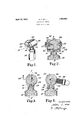
- Fig. 1 is a perspective view of my improved dlspensing cap mounted on a collapsible tube; g
- Fig. 2 is an enlarged vertical sectional View thereof taken on line 2-2of Fig. 3 i
- Fig. '3 is a sectional View takenon line 33 of Fig.2;and
- Fig. 4 is aview like Fig. 3 but showing'the' device in the dispensing position.
- 10 indicates a collapsible tube with my improved dispensing cap 12 screw threaded thereonto in place of the usualclosure cap, the cap 12 being provided H with a threaded boss 14 for this purpose.
- the boss'll projects downwardly from the body 16 of the device and has a passage 18 therein in communication with the tube out- I let when mounted on" the tube; m
- I provide a cylindrical valve member 20 for closing the passage 18 and dispensing the paste from the tube.
- This member is mounted on trunnions 22 between parallel walls 24 of a recess formed within the body 16. The trunnions extend through openings in such walls and holdthe peripheralsurface of the member in close slidingcontact with the arcuate wall 26 of the recess.
- a recess or depression 28 is,
- a helical spring 30 is mounted on one of the trunnions 22 within a recess 82 h in one end of the member 20.
- Fig. 4 the member 20 is shown in the V dispensing position, wherein the paste 36 can be directly removed by and to a brush 38. Any convenient means can be provided for moving the device to this position.
- I have illustrated a yoke 40 connected to the outer ends of the trunnions 22. The free end of the'yoke can be engaged against any convenient member and moved to and held in the stopped position, shown in Fig. 4, while the paste 36 is being removed.”
- a dispensing capfora tube or like container comprising a body part with a passage and a semi-cylindrical casing having parallel end'walls, a cylindricalvalve member fitting within the casing and having a longitudinal groove in its periphery and a chamber in one end, trunnion members upon which the valve member is journalled, one extend ing through said chamber, and a spring located'in said chamber, and arranged to hold the valve member normally in closed posi: tion, one of the end walls serving to close the chamber and thus enclose the spring.
- Avdispensing cap for a tube or likercontainer comprising a body part with a passage and a seml-cylindrical casing having parallel end walls, a cylindrical valve member mova 'bly fitting within the casing and having a longitudinal groove in its periphery and a chamber in one end,"and a'spring enclosedin said chamber and acting to hold the valve .-member at one limitof itsmovement, said 1 end walls serving to-close bothendsrof the groove and the spring-containing chamber.
Landscapes
- Engineering & Computer Science (AREA)
- Mechanical Engineering (AREA)
- Closures For Containers (AREA)
Description
H. C. BELL DISPENSING DEVICE April 12, 1932.
Filed July 7, 1930 i053" Wvavmm Patented Apr. 12, 1932 V UET STATES HOL'ION C. BELL, OF BEVERLY, MASSACHUSETTS DISPENSIN DEVICE Application filed Jul 7, 1930. Serial No. 465,823.
This invention relates to dispensing de vices, and more especially to a dispensing cap for tubular containers of the collapsible type commonly used for holding plastic material,
such as toothpaste, shaving cream, pigments, ointments, etc. Such containers as purchased are ordinarily closed by a threaded cap and it is proposed, according to my invention, to provide a dispensing cap which may be substituted for this closure cap and which, when so used, will serve the double purpose of keeping the tube closed and dispensing in a controlled manner material therefrom. I am aware that attempts have been made heretofore to provide devices of this general nature and I am familiar with Such devices and with their limitations in practical use. The primary object of my invention is to provide an improved device for use in this field which will be of practical value and will avoid the shortcomings of dispensing ca s heretofore available.
oothpastes and like plastic materials are ordinarily dispensed onto a brush andit is desirable to dispense the same in definite quantities or charges. It is, furthermore, desirable securely to protect the contents of the tube or container from exposure to the air at all times in order to avoid drying and oxidation. The dispensing cap of my invention is adapted to serve these several functions with great facility. It provides a tight and efficient closure for the tube at all times and acts automatically to close the tube be- 33 tween dispensing operations. Moreover, it controls the discharge of the contents of the tube so that it is impossible to waste the same or to dispense at one time more than a m measured charge. Further, it acts to confine the contents to interior surfaces so that the assembled tube and cap are always clean and convenient to handle.
In the accompanying drawings I have illustrated one specific embodiment of my invention but it will be understood that the invention can be otherwise embodied and that the drawings are not to be construed as defining or limiting the scope of the in W vention, the claims appended hereto being.
oi i d upon for that p P Referring to the figures of the drawings Fig. 1 is a perspective view of my improved dlspensing cap mounted on a collapsible tube; g
Fig. 2 is an enlarged vertical sectional View thereof taken on line 2-2of Fig. 3 i
Fig. '3 is a sectional View takenon line 33 of Fig.2;and
Fig. 4 is aview like Fig. 3 but showing'the' device in the dispensing position.
In the drawings, 10 indicatesa collapsible tube with my improved dispensing cap 12 screw threaded thereonto in place of the usualclosure cap, the cap 12 being provided H with a threaded boss 14 for this purpose. The boss'll projects downwardly from the body 16 of the device and has a passage 18 therein in communication with the tube out- I let when mounted on" the tube; m
As illustrated in the drawings, I provide a cylindrical valve member 20 for closing the passage 18 and dispensing the paste from the tube. This member is mounted on trunnions 22 between parallel walls 24 of a recess formed within the body 16. The trunnions extend through openings in such walls and holdthe peripheralsurface of the member in close slidingcontact with the arcuate wall 26 of the recess. A recess or depression 28 is,
formed in the member 20 from side to side i 2 thereof, the ends of the recess being open, and this recess is adapted to receive and dispense the material from the tube. 1 In Figs. 2 and S'the member 20 is shown in the closed and non-dispensing position. I prefer that thedevice shall normallyremain in this position and I may secure this action by providing'a spring for the purpose. As illustrated, a helical spring 30 is mounted on one of the trunnions 22 within a recess 82 h in one end of the member 20. One end of the spring'is secured to the member 20 and the otherend to a wall 24, so'that the normal actio-n of the spring holds the device in the positionshown in Figsi2' and 3, a stoppin 34 beingprovided on the member 20 for limit- 7 ing its rotary movement under the action of the spring. In this position the depression 28 is directly over and in communication with 313 the passage 18, whereby it is filled with paste when the tube is compressed.
In Fig. 4 the member 20 is shown in the V dispensing position, wherein the paste 36 can be directly removed by and to a brush 38. Any convenient means can be provided for moving the device to this position. In the drawings I have illustrated a yoke 40 connected to the outer ends of the trunnions 22. The free end of the'yoke can be engaged against any convenient member and moved to and held in the stopped position, shown in Fig. 4, while the paste 36 is being removed."
It is believed that the simple construction and operation of my device will be readily apparent. In use, it is threaded ontoa tube 10 in lieu of the usual closure cap and it at alltimes protects the contents of thetube from exposure to the air assecurely as does the closure cap. To dispense the-paste the tube is squeezed to fill the recess 28 and the member 20 is thereafter rotated to the position shown in Fig. 4. In this position the recess 28 is freely exposed and the open ends I thereof render the removal of the paste 36 onto the brush 38 an easy operation. It should, furthermore, be noted that the peripheral portion of the member 20 completely closes the passage 18 when the member isin the dispensing position. After the paste 36 is removed, the spring 38 automatically returns the member 20 to its normal position, in
which position the ends of the depression 28 are closed by the walls 24. r V
Having thus described myinvention, what I claim as new and desire to secure by Letters Patent is: a r
1. A dispensing capfora tube or like container, comprising a body part with a passage and a semi-cylindrical casing having parallel end'walls, a cylindricalvalve member fitting within the casing and having a longitudinal groove in its periphery and a chamber in one end, trunnion members upon which the valve member is journalled, one extend ing through said chamber, and a spring located'in said chamber, and arranged to hold the valve member normally in closed posi: tion, one of the end walls serving to close the chamber and thus enclose the spring. V 2. Avdispensing cap for a tube or likercontainer, comprising a body part with a passage and a seml-cylindrical casing having parallel end walls, a cylindrical valve member mova 'bly fitting within the casing and having a longitudinal groove in its periphery and a chamber in one end,"and a'spring enclosedin said chamber and acting to hold the valve .-member at one limitof itsmovement, said 1 end walls serving to-close bothendsrof the groove and the spring-containing chamber.
HUL'ION 'G. BELL.
Priority Applications (1)
| Application Number | Priority Date | Filing Date | Title |
|---|---|---|---|
| US465823A US1853493A (en) | 1930-07-07 | 1930-07-07 | Dispensing device |
Applications Claiming Priority (1)
| Application Number | Priority Date | Filing Date | Title |
|---|---|---|---|
| US465823A US1853493A (en) | 1930-07-07 | 1930-07-07 | Dispensing device |
Publications (1)
| Publication Number | Publication Date |
|---|---|
| US1853493A true US1853493A (en) | 1932-04-12 |
Family
ID=23849299
Family Applications (1)
| Application Number | Title | Priority Date | Filing Date |
|---|---|---|---|
| US465823A Expired - Lifetime US1853493A (en) | 1930-07-07 | 1930-07-07 | Dispensing device |
Country Status (1)
| Country | Link |
|---|---|
| US (1) | US1853493A (en) |
Cited By (2)
| Publication number | Priority date | Publication date | Assignee | Title |
|---|---|---|---|---|
| US2539283A (en) * | 1945-02-13 | 1951-01-23 | Robert M Strachan | Oscillatory metering chamber dispenser for small containers |
| US3318491A (en) * | 1965-06-14 | 1967-05-09 | Jervis C Williamson | Container having a trap-chamber dispensing means |
-
1930
- 1930-07-07 US US465823A patent/US1853493A/en not_active Expired - Lifetime
Cited By (2)
| Publication number | Priority date | Publication date | Assignee | Title |
|---|---|---|---|---|
| US2539283A (en) * | 1945-02-13 | 1951-01-23 | Robert M Strachan | Oscillatory metering chamber dispenser for small containers |
| US3318491A (en) * | 1965-06-14 | 1967-05-09 | Jervis C Williamson | Container having a trap-chamber dispensing means |
Similar Documents
| Publication | Publication Date | Title |
|---|---|---|
| US2743038A (en) | Paste dispenser | |
| US3035299A (en) | Dispenser | |
| US3985146A (en) | Disposable shaving kit | |
| US5732722A (en) | Cap for a toothpaste container having an incorporated spool of dental floss | |
| US2079744A (en) | Dispenser | |
| US1684313A (en) | Measuring and dispensing device | |
| US4074833A (en) | Dispensing container | |
| US2477875A (en) | Dispensing container for collapsible tube with axially movable, rotatively actuated,follower-type extruder | |
| US1853493A (en) | Dispensing device | |
| US1309900A (en) | Fountain bbush | |
| US3419191A (en) | Dispensing assembly | |
| US4963047A (en) | Dispensing brush | |
| US1374330A (en) | Brush | |
| US2067523A (en) | Dispensing device | |
| US1701433A (en) | Tube | |
| US2631763A (en) | Powder dispensing device | |
| US2063605A (en) | Measuring device | |
| US1154163A (en) | Dispensing-receptacle for paste, &c. | |
| US2851195A (en) | Dispensing device for collapsible tubes | |
| US3194441A (en) | Dispensing cap for tubular containers | |
| US2684790A (en) | Ejector-closure for collapsible tubes | |
| US1720096A (en) | Dispensing device | |
| US1395302A (en) | Dispensing device | |
| US2123731A (en) | Container | |
| US1199522A (en) | Dispensing-top for containers. |