US1853445A - Method for coloring motion picture films - Google Patents
Method for coloring motion picture films Download PDFInfo
- Publication number
- US1853445A US1853445A US357807A US35780729A US1853445A US 1853445 A US1853445 A US 1853445A US 357807 A US357807 A US 357807A US 35780729 A US35780729 A US 35780729A US 1853445 A US1853445 A US 1853445A
- Authority
- US
- United States
- Prior art keywords
- film
- films
- shaft
- coloring
- rollers
- Prior art date
- Legal status (The legal status is an assumption and is not a legal conclusion. Google has not performed a legal analysis and makes no representation as to the accuracy of the status listed.)
- Expired - Lifetime
Links
- 238000004040 coloring Methods 0.000 title description 34
- 238000000034 method Methods 0.000 title description 16
- 230000007246 mechanism Effects 0.000 description 11
- 239000000975 dye Substances 0.000 description 9
- 239000003086 colorant Substances 0.000 description 7
- XLYOFNOQVPJJNP-UHFFFAOYSA-N water Substances O XLYOFNOQVPJJNP-UHFFFAOYSA-N 0.000 description 5
- 239000011248 coating agent Substances 0.000 description 3
- 238000000576 coating method Methods 0.000 description 3
- 230000006835 compression Effects 0.000 description 3
- 238000007906 compression Methods 0.000 description 3
- 230000000694 effects Effects 0.000 description 3
- 229920000159 gelatin Polymers 0.000 description 3
- 235000019322 gelatine Nutrition 0.000 description 3
- 239000007788 liquid Substances 0.000 description 3
- 102000004726 Connectin Human genes 0.000 description 2
- 108010002947 Connectin Proteins 0.000 description 2
- 239000001828 Gelatine Substances 0.000 description 2
- 230000008901 benefit Effects 0.000 description 2
- 238000001035 drying Methods 0.000 description 2
- 238000005213 imbibition Methods 0.000 description 2
- 239000011159 matrix material Substances 0.000 description 2
- 239000002184 metal Substances 0.000 description 2
- 229930091051 Arenine Natural products 0.000 description 1
- 108010010803 Gelatin Proteins 0.000 description 1
- 238000010521 absorption reaction Methods 0.000 description 1
- 238000009792 diffusion process Methods 0.000 description 1
- 239000000835 fiber Substances 0.000 description 1
- 239000008273 gelatin Substances 0.000 description 1
- 235000011852 gelatine desserts Nutrition 0.000 description 1
- 238000004519 manufacturing process Methods 0.000 description 1
- 239000000463 material Substances 0.000 description 1
- 230000003204 osmotic effect Effects 0.000 description 1
- 230000009467 reduction Effects 0.000 description 1
- 229920006395 saturated elastomer Polymers 0.000 description 1
Images


Classifications
-
- G—PHYSICS
- G03—PHOTOGRAPHY; CINEMATOGRAPHY; ANALOGOUS TECHNIQUES USING WAVES OTHER THAN OPTICAL WAVES; ELECTROGRAPHY; HOLOGRAPHY
- G03D—APPARATUS FOR PROCESSING EXPOSED PHOTOGRAPHIC MATERIALS; ACCESSORIES THEREFOR
- G03D15/00—Apparatus for treating processed material
Definitions
- This invention relates to the coloring of motion picture films by what is generally known in the art as imbibition and osmosis, and the main object is to provide an improved method in which a transfer. of a coloring agent or, dye from a key film operating as a matrix or stencil is eifected by moving the key film and a subjective film in close contact and in accurate registration for a short interval or intervals of time.
- the main difficulty encountered heretofore has been in the provision of accurate means for moving key film and the subjective film in air tight contact, and in accurate registration for a sufiicient interval of time to effect a complete or suflicient transfer of color from 2 the key film to the subjective film.
- the characteristics of the key films carrying such dyes are therefore such that when the dyed portions of the film are moistened
- the dye contained thereon may be imparted the same on line 1717 and 1818 of Fig. 15.-
- imbibition to another surface by contact and pressure. This is generally termed imbibition.
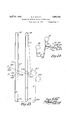
- Fig. 1 is a front elevation.
- Fig. 2 is a section on line 2-2 of Fig. 1.
- Fig. 3 is a view of a thin metallic connector for attaching portions of a film together.
- Fig. 4 is a right hand end elevation of the mechanism shown in Fig. 1.
- Fig. 5 is an enlarged view of an adjustable film moving device shown in Fig. 1.
- Figs. 6 and 7 are details of the film coloring means.
- Fig. 8 is a rear elevation of the machine.
- Fig. 9 is a sectional plan of the same on line 99.
- Figs. 10 and 11 are transverse sections on lines 1010 and 11-11 respectively, of Fig. 9.
- Fig. 12 is a. transverse section of Fig. 8 on line 12-12.
- Fig. 13 is a top plan View of the mechanism shown in Fig. 1.
- Fig. 14 is an enlarged front elevation of I Fig. 19 is a longitudinal section of the film coloring means on line 19-19 of Fig. 15.
- Fig. is a section of the film coloring means on line 2020 of Fig. 16.
- ig. 21 is an enlarged sectional elevation on line 21-21 of Fig. 13.
- Fig; 22 is a transverse section on l1ne 22-2 of Fig. 5. D
- Fig. 23 is a diagrammatic view in elevation of the film threaded through the machine as in a coloring operation.
- Fig. 24 is a diagrammatic front view of the film as it is fed to and from the film colorin means.
- e machine is generally arranged with a frame A of substantial proportions, having two different series of rollers mounted thereon at the top and bottom for'movably supporting and storing two separate films F and Said means includes upper and lower sets of rollers A1 and A2 associated with the film F, and corresponding sets of rollers A3 and A4 associated with the film F.
- ' F represents the color or key film from which color is adapted to be applied at selected areas in each of the frames to the subjective film F.
- Frame A has a forwardly projecting bed plate A9 on which is mounted a pair of lonitudinally spaced film feedin units B and D, includin brackets'B' and respectively, attache to the member A9.
- Bracket B adjustably supports a pair of film feeding sprockets F6 and F7 mounted one above the other and spaced a art for engagement with the films F and F respectively.
- the film F is-fed direct from the reel F1 to the sprocket F6, while the film F from reel F2 over 'a pair of rollers F8, F9 which are spaced apart and are supported on a bracket F10 which is submerged in a volume of water or other suitable liquid contained in a tank F11,
- the film F as it is fed from the reel F2 moves through the water or liquid in the tank-F11 so as to moisten the dye receiving surface thereon.
- a figred plate D8 connects members D2 and D3 above rollers D4 and carries a stud D9 which extends through the members D7 and has an adjusting nut D10 on the upper end thereof.
- a spring D11 is carried on the stud .D9 and is compressed between the nut D10 and the member D7 for tensioning the rollers D4 against the films F and F, which move beneath and in contact with the rollers as shown in Fig. 16.
- a horizontal plate D12 which forms a guideway on its upper and lower surfaces for a plurality of contact blocks D13, D13, etc.
- the late D12 is of suflicient length that it will movably support four of the blocks D13 on its upper surface; that is, one contact block for each of the rollers D4. Altogether there are nine of the blocks D13, five of which are always in the plane of the lower side of the plate D12, and four of which are in the plane of the upper side of said late.
- a ase plate D14 is provided below and spaced from the plate D12.
- the space between said plates corresponds to the thickness of the contact blocks D13, so that said blocks may move to the left, as seen in Fig. gii4and freely between the plates D12 and
- the plate D14 extends substantially to the left and right of the ends of the plate D12 and a pair of transverse blocks D15 and D16 are provided forwardly of plate D12 and are slidable respectivel on the side members D2 and D3, as hereina ter described.
- a top plate or plates D17 may be provided above the block D15 and connectin the side members D2 and D3.
- the block 16 is movable relative to the plate D12 to correspond to the width of one of the blocks D13, so that as the blocks D13 in succession are moved from the right hand and of plate D12, they may be guided downwardly at an angle and limited in their forward movement by engagement with the block D16, as each of the blocks in succession willassume the position represented by the formost block D13 adjacent the block D16 in Fig. 16.
- Each of the blocks D13 is provided with a diagonal slot D18 on each of its ends which is adapted to engage an inwardly turned portion D19 of a spring D20 which is fixed at its forward end D21 to the plates D2 or D3, as the case may be.
- the springs D20 overlie the forward ends of springs D49, which are fixed at points D50 to the plates D2 and D3, as shown in Fig. 14.
- Each of the blocks D13 has a pair of transversely alined lugs D22, D22 projecting upwardly therefrom and adapted to engage the perforations F12, F12 of the films F and F, as shown in Fig. 19, for the purpose of holding said films in accurate registration during the duration of their engagement with .the rollers D4 and the blocks D13.
- Frame member D3 rotatably supports a pair of short transverse shafts D23 and D24, as shown in Fig. 16, and said shafts carry, respectively, on their forward portions, crank discs D25 and D26 which are synchronously operated by means of a sprocket chain D27 which operably connects sprockets D28 and D29 on the rear ends of the shafts D23 and D24, respectively.
- Crank D26 is operably connected by means of a connecting rod D32 with a piston D30, which is reciprocably mounted in a vertically disposed cylinder D31 attached or formed on the plate D14 and the bore D33 of said c,ylinder is open at the upper surface of plate Power is applied to the shaft D23 as hereinafter described.
- Crank D25 is operably connected by means of a connecting rod D34 with a cross head D35 slidable on a bar D36 rigidly attached to the member D3 and parallels the plate D14.
- Cross head D35 has a lower portion D37 which is provided with notches D38 in the forward corner thereof, which are spaced apart laterally of the films F and F to correspond to the spacing of the lugs D22 on the contact blocks D13.
- the movement of the crank D25 effects the reciprocation of the cross head D35 relative to the rollers D4 and at each forward movement of said cross head the films F and F and uppermost tiers block D16 which engages the foremost block of said tier.
- the blocks D15 and D16 are provided at each end with a disc D39 attached to said blocks by means of screws D40 or otherwise, and said discs have trunnions D41 extending laterally therefrom which are held in the ends D42 of connecting rods D43.
- Said connectin rods have fittings D44 on the ends thereof w ich are swiveled on a transverse rod D45 which also serves to connect the connecting rod D34 with the cross head D35.
- the cross head D35 and blocks D15 and D16 reciprocate together and to a uniform extent.
- the discs D39 slidably engage slots D46 in the ends of members D2 and D3, as shown, for guiding the blocks D15 and D16 vin their movement.
- the block D13 in the extreme left hand end of the lowermost tier of such blocks is moved into position immediately above the piston D30 when the blocks D15 and D16 assume their extreme left hand positions, and immediately following such movement the piston D30 is thrust upwardly and elevates the left hand block D13 to the plane of the uppermosttier of such blocks.
- guide plate D12 The forward end of guide plate D12 is beveled at D46 so as to permit the free movement of the lower tierof blocks and especially the right hand block in such tier to operative position below the guide plate. It will be observedby reference to Figs. 17 and 18 that the guide plate D12 has longitudinal grooves D47 therein, and the rollersD4 are provided with annular grooves D48 at points to correspond to the position of and to permit the movement of the lugs D22 on blocks D13 relative to the guide plate and the rollers. v
- I may employ, when and if necessary,'an auxiliary water supply for dripping water or liquid into position between the films F and F in order to insure a close contact of the films and the expulsion of air from between the films during the color transfer operation. 7
- Such means may include a water tank E Vance of the rollers D4.
- va plurality of the coloring units D it may be advisable to employ va plurality of the coloring units D, and to thls end the fitting E3 is provided so that one of the drip pipes E4 may be connected with said fittingjor each coloring unit;
- the films and F move from the unit D they are adapted to engage sprockets C1 and C2, respectivel which are adjustably mounted on the brac et C and have yieldable follower rollers C3 and C4 employed in con- .nection therewith for holding the films in operative engagement with said sprockets.
- the sprockets C1 and C2 are adjustably mounted on the bracket C by means of a collar as'at C5 which embraces the shaft C6 of the sprocket C1.
- Said collar has a flange C7 which engages the forward side of the bracket C and loosely carries a telescoping collar C8 which is vertically adjustable in a Collar C8 has "a flange C10 which engages the rear side of member C and abuts a lock nut C11 which is threaded on the rear end of the collar C5.
- the nut serves to hold the roller C1 in adjusted position on the bracket.
- a similar means for holding the sprocket C2 is provided as shown in Fig. 21.
- the follower rollers C3 and C4 are mounted on arms C12 which are yieldably held in alinement with associated sprockets by means of compression springs C13 carried on end stems C14 adapted to compress between set collars C15 on said stems and bearings C16 held in the brackets C.
- the bracket C has a sprocket C17 associatedtherewith which is fixed to the shaft C6 and is adapted to operably connect with a similar sprocket C18 on shaft C19 of roller C2, by means of a sprocket chain C20 as shown in Fig. 4.
- a sprocket chain C20 as shown in Fig. 4.
- Shaft C6 also has a sprocket C21 frictionally connected therewith which connects with the shaft D23 by means of a chain C22, and to thisend engages a sprocket C23 on the shaft D23.
- Shaft G6 has a friction disc C24 fixed thereto which is frictionally connected with the sprocket C21 by means of a fibre or frictional disc of suitable material C25.
- a similar friction disc C26 may be interposed between and frictionally engage the sprockets C17 and C21.
- Shaft C19 is operably connected with a motor M through the instrumentality of means shown in ig. 1, which includes a worm gear M1 having a shaft M2 0 erabl connected with a s rocket C27 on sha t C19 by means of a chain 3.
- the motor is mounted on a suitable base M4 attached to the frame A, and is connected by means of a belt or chain M5 with a worm shaft M6.
- Said belt operates over a drivin pulley M7 fixed to the motor shaft M8 an a driven pulley M9 fixed to the worm shaft M6.
- Shafts M2 and M6 are suitably journaled in a frame M7 attached to the base M4, and the shaft- M6 carries a worm M8 in mesh with the worm gear M1.
- the shaft M2 may be sectional and comprise a clutch device M9 by means of which the driving chain M3 may be 0 eratively connected with and disconnected rom the worm gear shaft M2 at will.
- power is applied to the color transfer means and the film feeding means hereinabove described, from the motor M.
- the film actuating rollers C1 and C2, as shown in Fig. 21, should be selfa-djusting, and to this end they are frictionally driven by means of discs C28 C28 fixed to the enlarged portions C29 of said shafts.
- Friction discs C30, C30 are in terposed between the discs C28, C28 and the ends of the sprockets C1 and C2.
- the outer disc C28, the disc C30 and the rollers C1 and C2 are longitudinally slidable ;on their shaftsand are self-adjusting by reason of compression springs C31, C31 on the outer ends C32 of their shafts which compress between the discs C28 and a collar C33 associated with each of said rollers.
- Sprockets C1 and C2 are of the usual form and structure of devices employed in motion picture machines and are provided with the usual teeth for engagement with, the film perforations.
- the films F and F disengage the sprockets C1 and C2, respectively, as shown in Fig. 24, they are looped
- the shaft F21 of sprocket F15 carries a driving sprocket F22 adjacent the bracket F17, over which a chain F23 operates for driving the s'procket F 15 from a horizontal shaft F24 mounted on the frame A, as shown in Fig. 4.
- the film actuating sprocket F16 is mounted on shaft F24 and said shaft is driven as hereinafter described for moving the film F.
- Power is applied from shaft M2 by means of a sprocket chain G which operates over a sprocket G1 on a shaft G2 externally of frame A and supported thereon in suitable brackets G3, G3.
- Shaft G2 extends transversely across the right hand end of the frame A, and the brackets G3 are mounted on a portion A10 of said frame.
- Motion is communicated to shafts A5 and A7 at the top of the frame A through the medium of an elongated vertical shaft G4 which is journaled in bearings G5 and G6 of brackets G7 and G8 attached to the frame A near the end of the shaft G4.
- Shafts G2 and G4 are connected by means of bevel gears G9 and G10 respectively.
- a short verticalshaft G21 is mounted in bearings G11 and G12 on the frame A and is connected for operation with the shaft G2 by means of bevel gears Gl3and G14, respectively, fixed t0 shafts G21 and G2.
- a gear reduction shaft G15 is operably connected with a shaft G21 by means of bevel gears G16and G17 on said shafts, respectively.
- Shafts G15 and F24 are connected for operation by means of spur gears G18 and G19, respectively, fixed to said shafts.
- the ratio of gears G18 and G19 is such that the shafts F24 will operate at a substantially lesser speed than the shaft G15. This ratio is approximately four to one, so that the loops F13 and F14 are at all times maintained for the purpose of providing sufficient slack in the films F and F to prevent the tightening of the films as they are moved on their actuating sprockets.
- the shafts A5 and A7 at the top of the frame A which carry the rollers A1 and A3 are operably connected by means of a sprocket chain A15 which operates over sprockets as at A16 on each of the shafts A5 and A7.
- Shaft A5 is driven from the shaft G4 by means of bevel gears A17 and A18 on the shafts A5 and B4, respectively.
- a suitable clutch device A19having an op erating handle A20 may be employed in connection with the shaft A7 for the purpose of connecting and disconnecting said shaft from the shaft A5 at will.
- Fig. 23 it will be noted that the film F is moved from sprocket F15 over a roller F25, thence upwardly over alter nate rollers A3 and A4 throughout the entire series of suchrollers, and finally over a roller F26 and onto a take-01f reel F27.
- Film F is moved from sprocket F16 over a roller F28, and thence upwardly and downwardly over rollers A1 and A2 alternately throughout the entire series of such rollers, and finall over a rol er F29, and thence onto a take-off reel F30.
- Reel F30 is rotatabl mounted on the bracket F31 attached to t e rear of the frame 1n the manner shown in Fig. 9.
- the hub of said reel is fixed by means of a pin F32 with a portion F33 of the shaft F34 which is journaled in. bracket F31.
- the outer end of shaft F34 carries two sprockets F 35 and F36 which are frictionally mounted on the shaft by means of a spring held collar F37 shown in Flg, 11. which is keyed to a portion F38 of the shaft by means of a pin F39.
- Friction discs such as are shown in association with the rollers C1 and C2 are provided for frictionally connecting the sprockets F35 and F36 with the shaft F34.
- the frictional engagement of said elements is maintained by means of a compression spring F56 and a collar F40 on the extension of shaft F34.
- This structure is also typical of the take-01f reel F27.
- Sprocket F36 is connected with a similar sprocket on a horizontal shaft F43 geared to the frame A by means of a chain F44.
- Shaft F43 is journaled in brackets F45 and F46 attached to the frame A and is adapted to be operably connected with the shaft G2 by means of bevel gears F47 and G20 fixed to said shafts, respectively.
- I provide a collar F48 on the left hand end of the shaft F43, as shown in Fig. 8, which may be laterally removed from the shaft when a retaining pin F49 is removed therefrom.
- Said collar has a slot F50 therein which is closed by the in F49 for retaining the collar on the sha between the gear F47 and bracket F46 when said shaft is power operated.
- the removal of collar F48 will permit the slidin of the shaft F43 to the right, as shown in ig. 8, so as to unmesh the gears F47 and G20.
- a suitable crank F51 shown in Fig. 4 may be employed for connec-. tion with the end of shaft F43 for rotating said shaft on the reels F27 and F30 when said gears are disconnected.
- Ro lers F25, F26 and F29 are suitably mounted by means of brackets or suitable to the base A9 of the frame, from which the pilot film may be threaded over the rollers A1, A2, A3 and A4 and on the reels F27 and F30 at the beginning of a film coloring operation.
- the films F and F are then unwound from the reels F1 and F2, respectivel and threaded through sprockets F6 and F and thence through the coloring unit D, over sprockets C1 and C2, after which the ends of the films F and F may be attached to the ends of the pilot films by means of the metal connectors shown in Fig. 3.
- Said connectors are formed of thin metal plates I with laterally projecting teeth 5, 71, etc., thereon which are adapted to be bent at right angles upwardly through the perforations F12 of the films, and thence over the opposite sides of the films. Thereafter the films F and F will be drawn through the coloring unit D and over the drying rollers A1, A2, A3 and A4 and associated parts, and thence wound upon the reels F27 and F30 over the pilot film.
- the key of matrix film is colored in desired tints throughout all or portions of the areas of the successive frames. prior to a coloring operation.
- the films F and F are positives and have the same subjective matter thereon. Said s are threaded with corresponding frames in registration, and thereafter this registration and alinement of the images on the two films will be maintained throughout the colorin zone within the unit D.
- t is necessary that a separate key film F be provided for each of thedifi'erent colors imparted to the subjective film F, and therefore a subjective film F must be run through the coloring mechanism once for each color to be imparted thereto. If several different colors are applied to the subjective film, that is to say, difi'erent portions thereof colored differ -ently, each key film will carry but one of the colors throughout the portions thereof corresponding to the portions of the subjective film to be colored a given tint.
- Superposition of colors may be effected by tinting separate kev films F in the several primary colors, and thereafter running the films F and F, together through the coloring unit for as many times as are necessary to superpose the colors one upon the other and obtain a desired tint.
- the subjective film may be moved in contact with a key film which is colored blue, and thereafter again moved in contact with another key film which is colored red.
- Super-position of the blue on the red willimpart a purple tint to the subj ective film.
- the gelatine coating on the key film which has previously been saturated with a dye when moistened in contact with the subjective film will by osmotic action cause the diffusion of the dye from the gelatin on the key film and the absorption thereof by the gelatine on the subjective film.
- the subjective film will therefore partake of the color of the key film in all instances.
- the colorin unit D is so arranged that the fihns F an F will move through the coloring unit D in sli htly inclined planes, and that the contact b ocks D13 will follow each other in procession as shown in Fig. 16.
- the operation of the film actuating mechanism is quite slow as compared to other film actuating mechanisms in motion picture machines.
- the initial movement of the films is intermittent, while the final movement thereof is continuous and it is necessary that the coloring zone in the unit D should be disposed in a straight rather than in an arcuate path in order to maintain an arcuate register of the two films and to prevent any longitudinal adjustment'of one of the films with respect to the other;
- An advantage of the mechanism embodied i* the coloring unit is that the color is a plied to the subjective film in a relatively short period of time and throughout a very short portion of the length of the film. It has been found to be a distinct advantage to the coloring of films in this manner in preference to extending; the duration of the colorin g operation an increasing the length of the portions of the film which are held in contact with each other. In other words, it is much less diflicult to maintain an accurate register throughout a short interval of contact than for a longer interval.
- the method of coloring motion picture films which consists in moving a key film carrying a color in selected portions thereof in registration .and pressure contact with a moist subjective film with correspondin subject matter in close contact therewit between relatively rotatable and slidable elements fora distance corresponding to a plurality of frames of said film, for transferring the color from the keyfilm to corresponding portions of the subjective film.
- the method of coloring motion picture films which consists in moving the colored key film and the moistened subjective filmlin registration and in close contact with each other, between relatively rotatable tensioning means and slidable forwarding means for a 'ven distance for effecting a transfer of the color from the key film to corresponding portions of the subjective film.
- the method of coloring motion picture films which consists in supporting a colored 1 key film and a moistened subjective film in close contact on a series of slidable contact elements, simultaneously and intermittently moving said films and said contact elements for eifecting a transfer of the color from the key film to corresponding portions of the subjective film, and thereafter separately moving said films to and for disposition on a drier.
Landscapes
- Physics & Mathematics (AREA)
- General Physics & Mathematics (AREA)
- Photographic Processing Devices Using Wet Methods (AREA)
Description
April 12, 1932. R. C. MOCLAY METHOD FOR COLORING MOTION PICTURE FILMS Filed April 24 1929 7 Sheets-Sheet 1 1| ll! [1]] "INF.
I N VEN TOR.
NEY
April 12, 1932. R, C-MCCLAY 1,853,445
METHOD FOR COLORING MOTION PICTURE FILMS Filed April 24, 1929 Sheets-Sheet 2 April 12, 1932. R Q MCCLAY w 1,853,445
METHOD FOR COLORING MOTION PICTURE FILMS Filed April 24, 1929 7 Sheets-Sheet I5 I April 12,1932. I R Q M c I 1,853,445
METHOD FOR COLORING MOTION PICTURE FILMS Filed A ril 24, 1929 7 Sheets-Sheet 4 April 12, 1932. C C Y 1,853,445
METHOD FOR COLORING MOTION PICTURE FILMS Filed April 24, 1929 7, Sheets-Sheet 5 7 April 12, 1932. R C MCCLAY 1,853,445
METHOD FOR COLORING MOTION PICTURE FILMS Filed April 24, 1929 7 Sheets-Sheet 6 ApfTIZ, 1932. c. McCLAY 4 METHOD FOR COLORING MOTION PICTURE FILMS Filed April 24, 1929 7 Sheets-Sheet 7 Patented Apr. 12, 1932 UNITED STATES PATENT OFFICE ROY C. MCCLAT, OF LOS ANGELES, CALIFORNIA, ASSIGNOR TO FIRST NATIONALPBO- DUCTIONS CORPORATION, OF BURBANK, CALIFORNIA, A CORPORATION 01 DELA- WARE METHOD FOR COLORING Application filed April 24,
This invention relates to the coloring of motion picture films by what is generally known in the art as imbibition and osmosis, and the main object is to provide an improved method in which a transfer. of a coloring agent or, dye from a key film operating as a matrix or stencil is eifected by moving the key film and a subjective film in close contact and in accurate registration for a short interval or intervals of time.
In the consideration of this invention it may be understood that others have sought to accomplish the above objectsby means of other devices and the practice of other methods, but the same have not been successful or effective to an extent which adapted such means and methods to use in motion picture production laboratories.
The main difficulty encountered heretofore has been in the provision of accurate means for moving key film and the subjective film in air tight contact, and in accurate registration for a sufiicient interval of time to effect a complete or suflicient transfer of color from 2 the key film to the subjective film.
It is an object of this invention, therefore, to provide an improved method and means for accomplishing this specific result in connection with other well known features which I have illustrated in the drawings accompanying the disclosure of the improvements.
It will be understood that in the coloring of motion picture films a positive key film is so treated in the laboratories that the exposed portions of the films, ordinarily termed frames are in whole or inpart rendered susceptible to dyes of certain well known characteristics, whereby such portions of the key film may carry a quantity of dye by saturation in the gelatinous coating of the film. The film is rendered susceptible to the dyes by softening the gelatinous coating of the film in desired areas of each of the frames.
The characteristics of the key films carrying such dyes are therefore such that when the dyed portions of the film are moistened,
the dye contained thereon may be imparted the same on line 1717 and 1818 of Fig. 15.-
to another surface by contact and pressure. This is generally termed imbibition.
'It has been found necessary in order that MOTION PICTURE FILMS 1929. Serial No. 857,807.
with means for moistening the subjective film, for feeding the two films to the color transfer means, and for feeding and storing the two films subsequent to the color transferring operation.
Other objects will appear as the descriptionprogresses.
In the accompanying drawings I have shown a preferred form of a mechanism for the purpose described, in which:
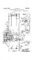
Fig. 1 is a front elevation.
Fig. 2 is a section on line 2-2 of Fig. 1.
Fig. 3 is a view of a thin metallic connector for attaching portions of a film together.
Fig. 4 is a right hand end elevation of the mechanism shown in Fig. 1.
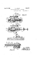
Fig. 5 is an enlarged view of an adjustable film moving device shown in Fig. 1.
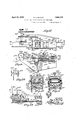
Figs. 6 and 7 are details of the film coloring means. Fig. 8 is a rear elevation of the machine. .Fig. 9 is a sectional plan of the same on line 99.
Figs. 10 and 11 are transverse sections on lines 1010 and 11-11 respectively, of Fig. 9. Fig. 12 is a. transverse section of Fig. 8 on line 12-12.
Fig. 13 is a top plan View of the mechanism shown in Fig. 1.
Fig. 14 is an enlarged front elevation of I Fig. 19 is a longitudinal section of the film coloring means on line 19-19 of Fig. 15.
luu
Fig. is a section of the film coloring means on line 2020 of Fig. 16.
ig. 21 is an enlarged sectional elevation on line 21-21 of Fig. 13.
Fig; 22 is a transverse section on l1ne 22-2 of Fig. 5. D
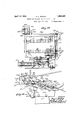
Fig. 23 is a diagrammatic view in elevation of the film threaded through the machine as in a coloring operation.
Fig. 24 is a diagrammatic front view of the film as it is fed to and from the film colorin means.
e machine is generally arranged with a frame A of substantial proportions, having two different series of rollers mounted thereon at the top and bottom for'movably supporting and storing two separate films F and Said means includes upper and lower sets of rollers A1 and A2 associated with the film F, and corresponding sets of rollers A3 and A4 associated with the film F.
means of members F3 and F4, respectively.
' F represents the color or key film from which color is adapted to be applied at selected areas in each of the frames to the subjective film F.
Frame A has a forwardly projecting bed plate A9 on which is mounted a pair of lonitudinally spaced film feedin units B and D, includin brackets'B' and respectively, attache to the member A9. Bracket B adjustably supports a pair of film feeding sprockets F6 and F7 mounted one above the other and spaced a art for engagement with the films F and F respectively. The film F is-fed direct from the reel F1 to the sprocket F6, while the film F from reel F2 over 'a pair of rollers F8, F9 which are spaced apart and are supported on a bracket F10 which is submerged in a volume of water or other suitable liquid contained in a tank F11,
mounted below the reel F2.
Thus the film F as it is fed from the reel F2 moves through the water or liquid in the tank-F11 so as to moisten the dye receiving surface thereon.
As shown in Fig. 24 it will be observed that the film F is twisted between the roller F9 and the sprocket F7 so that the outer surface of the film will be uppermost and in contact with the film F as the films are fed from rollers F6 and F7 to the right, as shown in Fi 1. I
e film coloring mechanism proper is shown at D intermediate the units B and C,
and embodies a suitable standard D1 mounted on the frame member A9 having spaced side members D2 and D3 attached to or inteverted U- haped member D7 w 'ch extends transversely across the upper edges of members D2 and D3.
A figred plate D8 connects members D2 and D3 above rollers D4 and carries a stud D9 which extends through the members D7 and has an adjusting nut D10 on the upper end thereof. A spring D11 is carried on the stud .D9 and is compressed between the nut D10 and the member D7 for tensioning the rollers D4 against the films F and F, which move beneath and in contact with the rollers as shown in Fig. 16.
Below the rollers and spaced therefrom is a horizontal plate D12 which forms a guideway on its upper and lower surfaces for a plurality of contact blocks D13, D13, etc.,
which as they move tothe right as seen in- Fig. 16'over the upper surface of the plate D12 hold the films F and F firmly in contact'with each other against the tension of spring D11 and the rollers D4.
It will be observed that in the form of device shown the late D12 is of suflicient length that it will movably support four of the blocks D13 on its upper surface; that is, one contact block for each of the rollers D4. Altogether there are nine of the blocks D13, five of which are always in the plane of the lower side of the plate D12, and four of which are in the plane of the upper side of said late.
A ase plate D14 is provided below and spaced from the plate D12. The space between said plates corresponds to the thickness of the contact blocks D13, so that said blocks may move to the left, as seen in Fig. gii4and freely between the plates D12 and The plate D14 extends substantially to the left and right of the ends of the plate D12 and a pair of transverse blocks D15 and D16 are provided forwardly of plate D12 and are slidable respectivel on the side members D2 and D3, as hereina ter described.
Said blocks are spaced apart slightly so as to permit the free movement of the films F and F therebetween. A top plate or plates D17 may be provided above the block D15 and connectin the side members D2 and D3.
The block 16 is movable relative to the plate D12 to correspond to the width of one of the blocks D13, so that as the blocks D13 in succession are moved from the right hand and of plate D12, they may be guided downwardly at an angle and limited in their forward movement by engagement with the block D16, as each of the blocks in succession willassume the position represented by the formost block D13 adjacent the block D16 in Fig. 16.
Each of the blocks D13 is provided with a diagonal slot D18 on each of its ends which is adapted to engage an inwardly turned portion D19 of a spring D20 which is fixed at its forward end D21 to the plates D2 or D3, as the case may be. The springs D20 overlie the forward ends of springs D49, which are fixed at points D50 to the plates D2 and D3, as shown in Fig. 14.
Each of the blocks D13 has a pair of transversely alined lugs D22, D22 projecting upwardly therefrom and adapted to engage the perforations F12, F12 of the films F and F, as shown in Fig. 19, for the purpose of holding said films in accurate registration during the duration of their engagement with .the rollers D4 and the blocks D13.
Frame member D3 rotatably supports a pair of short transverse shafts D23 and D24, as shown in Fig. 16, and said shafts carry, respectively, on their forward portions, crank discs D25 and D26 which are synchronously operated by means of a sprocket chain D27 which operably connects sprockets D28 and D29 on the rear ends of the shafts D23 and D24, respectively.
Crank D26 is operably connected by means of a connecting rod D32 with a piston D30, which is reciprocably mounted in a vertically disposed cylinder D31 attached or formed on the plate D14 and the bore D33 of said c,ylinder is open at the upper surface of plate Power is applied to the shaft D23 as hereinafter described.
Crank D25 is operably connected by means of a connecting rod D34 with a cross head D35 slidable on a bar D36 rigidly attached to the member D3 and parallels the plate D14. Cross head D35 has a lower portion D37 which is provided with notches D38 in the forward corner thereof, which are spaced apart laterally of the films F and F to correspond to the spacing of the lugs D22 on the contact blocks D13. The movement of the crank D25 effects the reciprocation of the cross head D35 relative to the rollers D4 and at each forward movement of said cross head the films F and F and uppermost tiers block D16 which engages the foremost block of said tier.
The blocks D15 and D16 are provided at each end with a disc D39 attached to said blocks by means of screws D40 or otherwise, and said discs have trunnions D41 extending laterally therefrom which are held in the ends D42 of connecting rods D43. Said connectin rods have fittings D44 on the ends thereof w ich are swiveled on a transverse rod D45 which also serves to connect the connecting rod D34 with the cross head D35. Thus the cross head D35 and blocks D15 and D16 reciprocate together and to a uniform extent.
The discs D39 slidably engage slots D46 in the ends of members D2 and D3, as shown, for guiding the blocks D15 and D16 vin their movement. The block D13 in the extreme left hand end of the lowermost tier of such blocks is moved into position immediately above the piston D30 when the blocks D15 and D16 assume their extreme left hand positions, and immediately following such movement the piston D30 is thrust upwardly and elevates the left hand block D13 to the plane of the uppermosttier of such blocks. At such times the lugs D22 on the block D13 will engage the recesses D38 in the cross head D35, and the resulting forward movement of the cross head will move the upper tier of blocks D13, namely, five in number, together with the films F and F forwardly over the guide plate D12, until the block so elevated will have assumed a position occupied by the left hand block in the upper tier, as shown in Fig. 16. a
In the meantime, the blocks D15 and D16 have moved forwardly to their extreme right hand positions, and the right hand block D13 in the upper tier has been moved downwardly into the position at the extreme right hand end of the lower tier in readiness for a succeeding operation.
The forward end of guide plate D12 is beveled at D46 so as to permit the free movement of the lower tierof blocks and especially the right hand block in such tier to operative position below the guide plate. It will be observedby reference to Figs. 17 and 18 that the guide plate D12 has longitudinal grooves D47 therein, and the rollersD4 are provided with annular grooves D48 at points to correspond to the position of and to permit the movement of the lugs D22 on blocks D13 relative to the guide plate and the rollers. v
I may employ, when and if necessary,'an auxiliary water supply for dripping water or liquid into position between the films F and F in order to insure a close contact of the films and the expulsion of air from between the films during the color transfer operation. 7
Such means may include a water tank E Vance of the rollers D4.
slot C9 in the member C.
In some cases it may be advisable to employ va plurality of the coloring units D, and to thls end the fitting E3 is provided so that one of the drip pipes E4 may be connected with said fittingjor each coloring unit;
As the films and F move from the unit D they are adapted to engage sprockets C1 and C2, respectivel which are adjustably mounted on the brac et C and have yieldable follower rollers C3 and C4 employed in con- .nection therewith for holding the films in operative engagement with said sprockets.
Referring to Fig. 21 it will be noted that the sprockets C1 and C2 are adjustably mounted on the bracket C by means of a collar as'at C5 which embraces the shaft C6 of the sprocket C1. Said collar has a flange C7 which engages the forward side of the bracket C and loosely carries a telescoping collar C8 which is vertically adjustable in a Collar C8 has "a flange C10 which engages the rear side of member C and abuts a lock nut C11 which is threaded on the rear end of the collar C5. Thus the nut serves to hold the roller C1 in adjusted position on the bracket. A similar means for holding the sprocket C2 is provided as shown in Fig. 21.
The follower rollers C3 and C4 are mounted on arms C12 which are yieldably held in alinement with associated sprockets by means of compression springs C13 carried on end stems C14 adapted to compress between set collars C15 on said stems and bearings C16 held in the brackets C.
The bracket C has a sprocket C17 associatedtherewith which is fixed to the shaft C6 and is adapted to operably connect with a similar sprocket C18 on shaft C19 of roller C2, by means of a sprocket chain C20 as shown in Fig. 4. Thus the shafts C6 and C19 will operate synchronously in the same direction for moving the films F and F away from the coloring mechanism.
Shaft C6 also has a sprocket C21 frictionally connected therewith which connects with the shaft D23 by means of a chain C22, and to thisend engages a sprocket C23 on the shaft D23. Shaft G6 has a friction disc C24 fixed thereto which is frictionally connected with the sprocket C21 by means of a fibre or frictional disc of suitable material C25.
A similar friction disc C26 may be interposed between and frictionally engage the sprockets C17 and C21. Shaft C19 is operably connected with a motor M through the instrumentality of means shown in ig. 1, which includes a worm gear M1 having a shaft M2 0 erabl connected with a s rocket C27 on sha t C19 by means of a chain 3.
The motor is mounted on a suitable base M4 attached to the frame A, and is connected by means of a belt or chain M5 with a worm shaft M6. Said belt operates over a drivin pulley M7 fixed to the motor shaft M8 an a driven pulley M9 fixed to the worm shaft M6. Shafts M2 and M6 are suitably journaled in a frame M7 attached to the base M4, and the shaft- M6 carries a worm M8 in mesh with the worm gear M1.
The shaft M2 may be sectional and comprise a clutch device M9 by means of which the driving chain M3 may be 0 eratively connected with and disconnected rom the worm gear shaft M2 at will. Thus, power is applied to the color transfer means and the film feeding means hereinabove described, from the motor M.
It is desirable that the film actuating rollers C1 and C2, as shown in Fig. 21, should be selfa-djusting, and to this end they are frictionally driven by means of discs C28 C28 fixed to the enlarged portions C29 of said shafts. Friction discs C30, C30 are in terposed between the discs C28, C28 and the ends of the sprockets C1 and C2.
The outer disc C28, the disc C30 and the rollers C1 and C2 are longitudinally slidable ;on their shaftsand are self-adjusting by reason of compression springs C31, C31 on the outer ends C32 of their shafts which compress between the discs C28 and a collar C33 associated with each of said rollers.
Sprockets C1 and C2 are of the usual form and structure of devices employed in motion picture machines and are provided with the usual teeth for engagement with, the film perforations. When the films F and F disengage the sprockets C1 and C2, respectively, as shown in Fig. 24, they are looped The shaft F21 of sprocket F15 carries a driving sprocket F22 adjacent the bracket F17, over which a chain F23 operates for driving the s'procket F 15 from a horizontal shaft F24 mounted on the frame A, as shown in Fig. 4. The film actuating sprocket F16 is mounted on shaft F24 and said shaft is driven as hereinafter described for moving the film F.
Power is applied from shaft M2 by means of a sprocket chain G which operates over a sprocket G1 on a shaft G2 externally of frame A and supported thereon in suitable brackets G3, G3. Shaft G2 extends transversely across the right hand end of the frame A, and the brackets G3 are mounted on a portion A10 of said frame.
Motion is communicated to shafts A5 and A7 at the top of the frame A through the medium of an elongated vertical shaft G4 which is journaled in bearings G5 and G6 of brackets G7 and G8 attached to the frame A near the end of the shaft G4. Shafts G2 and G4 are connected by means of bevel gears G9 and G10 respectively.
A short verticalshaft G21 is mounted in bearings G11 and G12 on the frame A and is connected for operation with the shaft G2 by means of bevel gears Gl3and G14, respectively, fixed t0 shafts G21 and G2. In a similar manner a gear reduction shaft G15 is operably connected with a shaft G21 by means of bevel gears G16and G17 on said shafts, respectively. Shafts G15 and F24 are connected for operation by means of spur gears G18 and G19, respectively, fixed to said shafts.
The ratio of gears G18 and G19 is such that the shafts F24 will operate at a substantially lesser speed than the shaft G15. This ratio is approximately four to one, so that the loops F13 and F14 are at all times maintained for the purpose of providing sufficient slack in the films F and F to prevent the tightening of the films as they are moved on their actuating sprockets.
In this connection it will be understood that the shaft F24 operates continuously, while the films F and F are advanced only intermittently due to the reciprocation of the cross head D35 which serves to advance the film frame by frame through the film coloring unit D. For this reason it is necessary to maintain substantial loops in the films between the point of egress from the unit D and their points of engagement with the sprockets F15 and F16.
The shafts A5 and A7 at the top of the frame A which carry the rollers A1 and A3 are operably connected by means of a sprocket chain A15 which operates over sprockets as at A16 on each of the shafts A5 and A7. Shaft A5 is driven from the shaft G4 by means of bevel gears A17 and A18 on the shafts A5 and B4, respectively.
A suitable clutch device A19having an op erating handle A20 may be employed in connection with the shaft A7 for the purpose of connecting and disconnecting said shaft from the shaft A5 at will.
Now, referring to Fig. 23 it will be noted that the film F is moved from sprocket F15 over a roller F25, thence upwardly over alter nate rollers A3 and A4 throughout the entire series of suchrollers, and finally over a roller F26 and onto a take-01f reel F27. Film F, however is moved from sprocket F16 over a roller F28, and thence upwardly and downwardly over rollers A1 and A2 alternately throughout the entire series of such rollers, and finall over a rol er F29, and thence onto a take-off reel F30.
Reel F30 is rotatabl mounted on the bracket F31 attached to t e rear of the frame 1n the manner shown in Fig. 9. The hub of said reel is fixed by means of a pin F32 with a portion F33 of the shaft F34 which is journaled in. bracket F31. The outer end of shaft F34, carries two sprockets F 35 and F36 which are frictionally mounted on the shaft by means of a spring held collar F37 shown in Flg, 11. which is keyed to a portion F38 of the shaft by means of a pin F39.
Friction discs such as are shown in association with the rollers C1 and C2 are provided for frictionally connecting the sprockets F35 and F36 with the shaft F34. The frictional engagement of said elements is maintained by means of a compression spring F56 and a collar F40 on the extension of shaft F34. This structure is also typical of the take-01f reel F27.
Sprocket F36 is connected with a similar sprocket on a horizontal shaft F43 geared to the frame A by means of a chain F44. Shaft F43 is journaled in brackets F45 and F46 attached to the frame A and is adapted to be operably connected with the shaft G2 by means of bevel gears F47 and G20 fixed to said shafts, respectively.
Thus, by means of the mechanism described all of the film carrying reels, rollers and sprockets are interconnected for simultaneous operation for feeding the films F and F' throughout a complete cycle of operation. In this respect it is to be noted that the exposure of the film in the frame A when suspended on the rollers A1, A2 and A3 and A4 will effect the drying of the films before they are wound on the reels F27 and F30.
It is frequently desirable, however, to disconnect the shaft F43 from the shaft G2, and
for this purpose I provide a collar F48 on the left hand end of the shaft F43, as shown in Fig. 8, which may be laterally removed from the shaft when a retaining pin F49 is removed therefrom.- Said collar has a slot F50 therein which is closed by the in F49 for retaining the collar on the sha between the gear F47 and bracket F46 when said shaft is power operated. The removal of collar F48 will permit the slidin of the shaft F43 to the right, as shown in ig. 8, so as to unmesh the gears F47 and G20. A suitable crank F51 shown in Fig. 4 may be employed for connec-. tion with the end of shaft F43 for rotating said shaft on the reels F27 and F30 when said gears are disconnected.
A pin F52 at the end of shaft F43 engages a slot F53 in the end of the crank whereby the crank may be. operably connected for ro tatin the shaft.
Ro lers F25, F26 and F29 are suitably mounted by means of brackets or suitable to the base A9 of the frame, from which the pilot film may be threaded over the rollers A1, A2, A3 and A4 and on the reels F27 and F30 at the beginning of a film coloring operation. The films F and F are then unwound from the reels F1 and F2, respectivel and threaded through sprockets F6 and F and thence through the coloring unit D, over sprockets C1 and C2, after which the ends of the films F and F may be attached to the ends of the pilot films by means of the metal connectors shown in Fig. 3.
Said connectors are formed of thin metal plates I with laterally projecting teeth 5, 71, etc., thereon which are adapted to be bent at right angles upwardly through the perforations F12 of the films, and thence over the opposite sides of the films. Thereafter the films F and F will be drawn through the coloring unit D and over the drying rollers A1, A2, A3 and A4 and associated parts, and thence wound upon the reels F27 and F30 over the pilot film.
The key of matrix film is colored in desired tints throughout all or portions of the areas of the successive frames. prior to a coloring operation.
The films F and F are positives and have the same subjective matter thereon. Said s are threaded with corresponding frames in registration, and thereafter this registration and alinement of the images on the two films will be maintained throughout the colorin zone within the unit D.
t is necessary that a separate key film F be provided for each of thedifi'erent colors imparted to the subjective film F, and therefore a subjective film F must be run through the coloring mechanism once for each color to be imparted thereto. If several different colors are applied to the subjective film, that is to say, difi'erent portions thereof colored differ -ently, each key film will carry but one of the colors throughout the portions thereof corresponding to the portions of the subjective film to be colored a given tint.
Superposition of colors may be effected by tinting separate kev films F in the several primary colors, and thereafter running the films F and F, together through the coloring unit for as many times as are necessary to superpose the colors one upon the other and obtain a desired tint.
For instance, the subjective film may be moved in contact with a key film which is colored blue, and thereafter again moved in contact with another key film which is colored red. Super-position of the blue on the red .willimpart a purple tint to the subj ective film.
The moistening of the subject film F both in the receptacle F11 and by means of the drip pipe E4 will cause an adhesion of the films F and F together, and the expulsion of air from therebetween when the two films are moved in accurate registration through the film coloring mechanism D and'between the tension rollers D4 and contact blocks D13.
The gelatine coating on the key film which has previously been saturated with a dye, when moistened in contact with the subjective film will by osmotic action cause the diffusion of the dye from the gelatin on the key film and the absorption thereof by the gelatine on the subjective film. The subjective film will therefore partake of the color of the key film in all instances.
In the consideration of this invention it may be understood that the colorin unit D is so arranged that the fihns F an F will move through the coloring unit D in sli htly inclined planes, and that the contact b ocks D13 will follow each other in procession as shown in Fig. 16.
It should be further understood that the operation of the film actuating mechanism is quite slow as compared to other film actuating mechanisms in motion picture machines. The initial movement of the films is intermittent, while the final movement thereof is continuous and it is necessary that the coloring zone in the unit D should be disposed in a straight rather than in an arcuate path in order to maintain an arcuate register of the two films and to prevent any longitudinal adjustment'of one of the films with respect to the other;
An advantage of the mechanism embodied i* the coloring unit is that the color is a plied to the subjective film in a relatively short period of time and throughout a very short portion of the length of the film. It has been found to be a distinct advantage to the coloring of films in this manner in preference to extending; the duration of the colorin g operation an increasing the length of the portions of the film which are held in contact with each other. In other words, it is much less diflicult to maintain an accurate register throughout a short interval of contact than for a longer interval.
I What I claim is:
1. The method of coloring motion picture films which consists in moving a key film carrying a color in selected portions thereof in registration .and pressure contact with a moist subjective film with correspondin subject matter in close contact therewit between relatively rotatable and slidable elements fora distance corresponding to a plurality of frames of said film, for transferring the color from the keyfilm to corresponding portions of the subjective film.
2. The method of coloring motion picture films which consists in moving the colored key film and the moistened subjective filmlin registration and in close contact with each other, between relatively rotatable tensioning means and slidable forwarding means for a 'ven distance for effecting a transfer of the color from the key film to corresponding portions of the subjective film.
3. The method of coloring motion picture films which consists in supporting a colored 1 key film and a moistened subjective film in close contact on a series of slidable contact elements, simultaneously and intermittently moving said films and said contact elements for eifecting a transfer of the color from the key film to corresponding portions of the subjective film, and thereafter separately moving said films to and for disposition on a drier.
ROY G. McOLAY.
Priority Applications (1)
| Application Number | Priority Date | Filing Date | Title |
|---|---|---|---|
| US357807A US1853445A (en) | 1929-04-24 | 1929-04-24 | Method for coloring motion picture films |
Applications Claiming Priority (1)
| Application Number | Priority Date | Filing Date | Title |
|---|---|---|---|
| US357807A US1853445A (en) | 1929-04-24 | 1929-04-24 | Method for coloring motion picture films |
Publications (1)
| Publication Number | Publication Date |
|---|---|
| US1853445A true US1853445A (en) | 1932-04-12 |
Family
ID=23407107
Family Applications (1)
| Application Number | Title | Priority Date | Filing Date |
|---|---|---|---|
| US357807A Expired - Lifetime US1853445A (en) | 1929-04-24 | 1929-04-24 | Method for coloring motion picture films |
Country Status (1)
| Country | Link |
|---|---|
| US (1) | US1853445A (en) |
Cited By (1)
| Publication number | Priority date | Publication date | Assignee | Title |
|---|---|---|---|---|
| US2572001A (en) * | 1949-01-03 | 1951-10-23 | Technicolor Motion Picture | Method and apparatus for transferring picture layers from one film base to another |
-
1929
- 1929-04-24 US US357807A patent/US1853445A/en not_active Expired - Lifetime
Cited By (1)
| Publication number | Priority date | Publication date | Assignee | Title |
|---|---|---|---|---|
| US2572001A (en) * | 1949-01-03 | 1951-10-23 | Technicolor Motion Picture | Method and apparatus for transferring picture layers from one film base to another |
Similar Documents
| Publication | Publication Date | Title |
|---|---|---|
| DE961784C (en) | Method and device for coating a moving carrier sheet with a viscous aqueous mass | |
| US1853445A (en) | Method for coloring motion picture films | |
| DE3942394C2 (en) | Device for developing photographic substrates | |
| US2100148A (en) | Apparatus for producing images | |
| US1707710A (en) | Method and apparatus for imbibition printing | |
| DE813079C (en) | Process for the production of films from polymeric resins | |
| US2134483A (en) | Apparatus for printing motion picture color film | |
| US1984456A (en) | Sound-record cinematograph films in natural colors | |
| US1560541A (en) | Film-dyeing apparatus | |
| US1316791A (en) | Process | |
| US1495678A (en) | Film-developing apparatus | |
| US1682943A (en) | Apparatus for treating films | |
| US2986996A (en) | Apparatus for and method of imbibition printing | |
| US1834355A (en) | Machine for the production of cinematograph and other films | |
| US1713220A (en) | Plural-row cinematographic camera | |
| US1986107A (en) | Apparatus for developing sound track motion picture film | |
| US1677309A (en) | Registering and cementing cinematographic films | |
| US1717957A (en) | Film printer | |
| DE859712C (en) | Exposure device for the production of photo engravings on fabric printing rollers | |
| US1569027A (en) | Method and apparatus for the accurate reproduction of paintings, drawings, or prints of all kinds with colored elements of any description | |
| CH148149A (en) | Process and apparatus for producing photographic reproductions by means of reflected light rays without a camera. | |
| DE476203C (en) | Device for printing cinema films using the absorption process | |
| US1323767A (en) | Machine for printing films for colored motion pictures | |
| DE324475C (en) | Device for copying motion pictures | |
| US1915560A (en) | Machine for the production of cinematograph and other films |