US1853434A - Rotary shears - Google Patents
Rotary shears Download PDFInfo
- Publication number
- US1853434A US1853434A US508349A US50834931A US1853434A US 1853434 A US1853434 A US 1853434A US 508349 A US508349 A US 508349A US 50834931 A US50834931 A US 50834931A US 1853434 A US1853434 A US 1853434A
- Authority
- US
- United States
- Prior art keywords
- knife holder
- guide
- roller
- swinging
- rotary
- Prior art date
- Legal status (The legal status is an assumption and is not a legal conclusion. Google has not performed a legal analysis and makes no representation as to the accuracy of the status listed.)
- Expired - Lifetime
Links
- 238000010008 shearing Methods 0.000 description 8
- 239000002184 metal Substances 0.000 description 5
- 230000009471 action Effects 0.000 description 3
- 238000010276 construction Methods 0.000 description 2
- 239000000463 material Substances 0.000 description 2
- 230000007246 mechanism Effects 0.000 description 2
- 230000008878 coupling Effects 0.000 description 1
- 238000010168 coupling process Methods 0.000 description 1
- 238000005859 coupling reaction Methods 0.000 description 1
- 230000004048 modification Effects 0.000 description 1
- 238000012986 modification Methods 0.000 description 1
- 230000009467 reduction Effects 0.000 description 1
Images

Classifications
-
- B—PERFORMING OPERATIONS; TRANSPORTING
- B23—MACHINE TOOLS; METAL-WORKING NOT OTHERWISE PROVIDED FOR
- B23D—PLANING; SLOTTING; SHEARING; BROACHING; SAWING; FILING; SCRAPING; LIKE OPERATIONS FOR WORKING METAL BY REMOVING MATERIAL, NOT OTHERWISE PROVIDED FOR
- B23D25/00—Machines or arrangements for shearing stock while the latter is travelling otherwise than in the direction of the cut
- B23D25/02—Flying shearing machines
- B23D25/08—Flying shearing machines having two coacting shearing blades mounted independently
-
- Y—GENERAL TAGGING OF NEW TECHNOLOGICAL DEVELOPMENTS; GENERAL TAGGING OF CROSS-SECTIONAL TECHNOLOGIES SPANNING OVER SEVERAL SECTIONS OF THE IPC; TECHNICAL SUBJECTS COVERED BY FORMER USPC CROSS-REFERENCE ART COLLECTIONS [XRACs] AND DIGESTS
- Y10—TECHNICAL SUBJECTS COVERED BY FORMER USPC
- Y10T—TECHNICAL SUBJECTS COVERED BY FORMER US CLASSIFICATION
- Y10T83/00—Cutting
- Y10T83/465—Cutting motion of tool has component in direction of moving work
- Y10T83/4766—Orbital motion of cutting blade
- Y10T83/4795—Rotary tool
- Y10T83/4812—Compound movement of tool during tool cycle
Definitions
- This invention relates to rotary shears for use in shearing the ends of bars passing through a continuous mill or the like, the shears being'operative to crop or sever the 5 -cold ends of the bars while the latter are moving. 7
- Figure 1 Figure 3 a similar view taken along the line IIIIII, Figure 1; and Figure 4 a section of the cutting and guiding mechanism diagrammatically illustrating the position of D the knife holder and its guiding means'during the operating cycle.
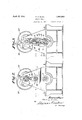
- the structure therein illustrated comprises a suitable framework 1 in which is journaled a pair of shafts .2 and 3 with their axes in parallel alinement, the shaft 3 being conected through coupling 4 to a suitable clutch and gear reduction unit, generally designated at 5, designed to operate the shear in l a manner to co-ordinate it with the operationof the mill.
- Shafts 2 and- 3 are connected through gear wheels 6 and .7 so that the shaft 2 is positively driven as is shaft 3.
- shaft 3 mounted on shaft 3 is a knife holder 8 which is secured to rotate with the shaft by keys 9, the knife holder being provided with a knife 10 as shown in Figures 3 and 4.
- Shaft 2 is rovided with a pair of arms 11 and 12 whicl 'l are secured to the shaft 2 by keys 13.
- the arms pivotally engage trunnions 14 of a swinging knife holder 15 carrymg knife 16, the knife holder being provided with bifurcated ends or yokes 17 which co- -operate with rollers 18 that are journaled in 65 lugs 19 of the bottom knife holder8.
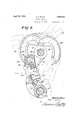
- an arm 20 which carries aProller or follower 21 that 0peratesin a guide 22 secured to the frame of the machine,-the guide 22 being of such contour as to guide the knife holder in a manner to bring its yoke portions in alinement with roller 18 of the bottom knife holder as shown in Figure 4 of the drawings.
- the operation of the rotary shear is briefly 6 as follows: The bars are passed between the knives which latter are rotated in clockwise direction as viewed in Figure 4, the material passing from the left to the right hand side of the knives.
- the knife holder 15 is shown 7 in four positions in Figure, the full line position being the initial position in which the knives are approaching their cutting action as they come into engagement with the bars to be cut. In this position, the roller 18 is entering the slide of the yoke 17 and the roller 21 is leaving the guide 22.
- the roller 18 and yoke 17 cooperate to maintain the knives in proper alinement which is substantially parallel during the cutting cycle.
- roller 18 is shown as leaving the yoke 17 and roller 21 as entering the guide 22.
- roller 21 is shown passing through the guide and. causing the knife holder to swing in such manner that its yoke portion will be in alinement to receive roller 18 of the knife holder 8 when the pivotally mounted knife holder 15 again reaches its initial cutting osition.
- Metal cutting shears comprising in combination a pair of rotary shafts journaled in a frame with their axes in parallel alinement, a swinging knife holder mounted on the upper of said shafts and a knife holder mounted on the lower shaft, a guide and roller associated with said knife holders to maintain the knives in substantial alinement during their shearing action and means for guiding said swinging knife holder during its rotating movement to bringthe guide and roller in register at the beginning of the shearing operation.
- Metal cutting shears comprising in combination a pair of rotar shafts journaled in a frame with their axes in parallel alinement, a swinging knife holder mounted on the upper of said shafts and a knife holder mounted on the lower shaft, said swinging knife holder having a guide and said lower knife holder a roller adapted for cooperative engagement with said guide, and means associated with said swinging knife holder for guiding the latter in its rotating movement to cause the guide and roller to register at the beginning of the shearing operation.
- Metal cutting shears comprising in combination a pair of rotary shafts journaled in I a frame with their axes in parallel alinement, a swinging knife holder mounted on one of said shafts and a knife holder fixedly mounted on the other of said shafts, said swinging knife holder having a guide at each end and rollers to register at the beginning of the shearing operation.
- Metal cutting shears comprising in combination a frame, a pair of rotary shafts journaled in said frame with their axes in parallel alinement, a pair of arms keyed to one of said shafts, a swinging knife holder having trunnions journaled in said arms, a second knife holder fixedly mounted on the other of said shafts, said swinging knife holder having a guide at each end and said second knife holder having rollers at each end adapted for cooperative engagement with said guides, and means including an arm on said swinging knife holder and a fixed guide on said frame for guiding said swinging knife holder in its rotating movement to cause said guides at each 'end of said swinging knife holder and said rollers on said second knife holder to register at the beginning of the shearing operation.
- said other knife holder having a roller at each end adapted for cooperative engagement with said guides, and means including an arm on said swinging knife holderand a fixed guide on the frame of the shear for guiding said swinging knife holder in its rotating movement to cause said guides at each end of said swingin knife holder and said rollers on said fixed ife holder to register at the beginnin of the shearing operation.
- Metal cutting shears comprising in comparallel alinement, a swinging knife holder mounted on one of said shafts and a knife holder fixedly mounted on the other of said shafts, said swinging knife holder havin a guide at each end and said'other knife holder having a roller at each end and adapted for cooperative engagement with said guides, and means associated with said swinging tating movement to cause said guides and bination a frame, a pair of rotary shaftsournaled in said frame with their axes in knife holder for guiding the latter in its ro.
Landscapes
- Engineering & Computer Science (AREA)
- Mechanical Engineering (AREA)
- Shearing Machines (AREA)
Description
F E. KLING ROTARY SHEARS April 12, 1932. Y
3 Sheets-Sheet 1 Filed Jan. v12, 1931 L Willi 1| \IIIIIMIHIIHHI I I NHM N bwendor: fie 50 E. KL/NG,
April 12, 1932. F. E. KLING ROTARY SHEARS s Shets-Sheet 2 Filed Jan; 12, 1931 fiwevzior:
FEED .5 Au/vc; m 1
April 12, 1932, E, G 1,853,434
I ROTARY SHEARS t Filed Jan 12, 1931 3 Sheets-Sheet 3 6/5 w'ameyg Patented Apr. 12, 1932 PJATENT OFFICE FRED 1:. arms, or rouncsrown, OHIO ROTARY snnaias Application filed January 12, 1931. Serial No. 508,349.
This invention relates to rotary shears for use in shearing the ends of bars passing through a continuous mill or the like, the shears being'operative to crop or sever the 5 -cold ends of the bars while the latter are moving. 7
It is among the objects of the invention to provide a shear in which the cutting knives are mounted in substantial alinement during the shearing cycle and in which provision is made to guide the movable lgnife holder during its rotary movement so that it will register with the cooperating element of the other knife member when they are brought into cutting position.
To this end a simple and mechanically durable construction is provided which will become more apparent from a consideration of the accompanying drawings constituting D a part hereof and in which like reference characters designate like parts and in which Figure 1 is a sectional elevational view of a rotary shear embodying the principles of this invention; Figure 2a vertical sectional ele- 5 vational view taken along the line IIII,
Figure 1; Figure 3 a similar view taken along the line IIIIII, Figure 1; and Figure 4 a section of the cutting and guiding mechanism diagrammatically illustrating the position of D the knife holder and its guiding means'during the operating cycle. a
With reference to the several figures of the drawings, the structure therein illustrated comprises a suitable framework 1 in which is journaled a pair of shafts .2 and 3 with their axes in parallel alinement, the shaft 3 being conected through coupling 4 to a suitable clutch and gear reduction unit, generally designated at 5, designed to operate the shear in l a manner to co-ordinate it with the operationof the mill.
The operation of the rotary shear is briefly 6 as follows: The bars are passed between the knives which latter are rotated in clockwise direction as viewed in Figure 4, the material passing from the left to the right hand side of the knives. The knife holder 15 is shown 7 in four positions in Figure, the full line position being the initial position in which the knives are approaching their cutting action as they come into engagement with the bars to be cut. In this position, the roller 18 is entering the slide of the yoke 17 and the roller 21 is leaving the guide 22. Thus, when the knives are brought into cutting engagenrent with the 'material, the roller 18 and yoke 17 cooperate to maintain the knives in proper alinement which is substantially parallel during the cutting cycle.
In the first dotted line position on the right hand side of the figure, roller 18 is shown as leaving the yoke 17 and roller 21 as entering the guide 22. In the second upper position the roller 21 is shown passing through the guide and. causing the knife holder to swing in such manner that its yoke portion will be in alinement to receive roller 18 of the knife holder 8 when the pivotally mounted knife holder 15 again reaches its initial cutting osition.
From the foregoing description it will be evident that by the roller and guide mechanism, a pivotally mounted knife holder may be employed in a rotary shear to provide alinement of the cutting members during their cutting action and to bring the mem- 5 will be obvious to those skilled in the art that various modifications may be made in the details of construction without departing from the principles herein set forth.
I claim:
10 1. Metal cutting shears comprising in combination a pair of rotary shafts journaled in a frame with their axes in parallel alinement, a swinging knife holder mounted on the upper of said shafts and a knife holder mounted on the lower shaft, a guide and roller associated with said knife holders to maintain the knives in substantial alinement during their shearing action and means for guiding said swinging knife holder during its rotating movement to bringthe guide and roller in register at the beginning of the shearing operation.
2. Metal cutting shears comprising in combination a pair of rotar shafts journaled in a frame with their axes in parallel alinement, a swinging knife holder mounted on the upper of said shafts and a knife holder mounted on the lower shaft, said swinging knife holder having a guide and said lower knife holder a roller adapted for cooperative engagement with said guide, and means associated with said swinging knife holder for guiding the latter in its rotating movement to cause the guide and roller to register at the beginning of the shearing operation.
3. Metal cutting shears comprising in combination a pair of rotary shafts journaled in I a frame with their axes in parallel alinement, a swinging knife holder mounted on one of said shafts and a knife holder fixedly mounted on the other of said shafts, said swinging knife holder having a guide at each end and rollers to register at the beginning of the shearing operation. a a
5. Metal cutting shears comprising in combination a frame, a pair of rotary shafts journaled in said frame with their axes in parallel alinement, a pair of arms keyed to one of said shafts, a swinging knife holder having trunnions journaled in said arms, a second knife holder fixedly mounted on the other of said shafts, said swinging knife holder having a guide at each end and said second knife holder having rollers at each end adapted for cooperative engagement with said guides, and means including an arm on said swinging knife holder and a fixed guide on said frame for guiding said swinging knife holder in its rotating movement to cause said guides at each 'end of said swinging knife holder and said rollers on said second knife holder to register at the beginning of the shearing operation.
In testimony whereof, I have hereunto set my hand.
" FRED E. KLING.
said other knife holder having a roller at each end adapted for cooperative engagement with said guides, and means including an arm on said swinging knife holderand a fixed guide on the frame of the shear for guiding said swinging knife holder in its rotating movement to cause said guides at each end of said swingin knife holder and said rollers on said fixed ife holder to register at the beginnin of the shearing operation.
4. Metal cutting shears comprising in comparallel alinement, a swinging knife holder mounted on one of said shafts and a knife holder fixedly mounted on the other of said shafts, said swinging knife holder havin a guide at each end and said'other knife holder having a roller at each end and adapted for cooperative engagement with said guides, and means associated with said swinging tating movement to cause said guides and bination a frame, a pair of rotary shaftsournaled in said frame with their axes in knife holder for guiding the latter in its ro.-
Priority Applications (1)
| Application Number | Priority Date | Filing Date | Title |
|---|---|---|---|
| US508349A US1853434A (en) | 1931-01-12 | 1931-01-12 | Rotary shears |
Applications Claiming Priority (1)
| Application Number | Priority Date | Filing Date | Title |
|---|---|---|---|
| US508349A US1853434A (en) | 1931-01-12 | 1931-01-12 | Rotary shears |
Publications (1)
| Publication Number | Publication Date |
|---|---|
| US1853434A true US1853434A (en) | 1932-04-12 |
Family
ID=24022394
Family Applications (1)
| Application Number | Title | Priority Date | Filing Date |
|---|---|---|---|
| US508349A Expired - Lifetime US1853434A (en) | 1931-01-12 | 1931-01-12 | Rotary shears |
Country Status (1)
| Country | Link |
|---|---|
| US (1) | US1853434A (en) |
Cited By (1)
| Publication number | Priority date | Publication date | Assignee | Title |
|---|---|---|---|---|
| US3750511A (en) * | 1971-08-02 | 1973-08-07 | Minnesota Mining & Mfg | Tape severing device |
-
1931
- 1931-01-12 US US508349A patent/US1853434A/en not_active Expired - Lifetime
Cited By (1)
| Publication number | Priority date | Publication date | Assignee | Title |
|---|---|---|---|---|
| US3750511A (en) * | 1971-08-02 | 1973-08-07 | Minnesota Mining & Mfg | Tape severing device |
Similar Documents
| Publication | Publication Date | Title |
|---|---|---|
| US2261007A (en) | Reciprocating flying shear | |
| US1802554A (en) | Rotary flying shears | |
| US1969433A (en) | Flying shear | |
| US1853434A (en) | Rotary shears | |
| US1948139A (en) | Rotary flying shear | |
| US3121361A (en) | Shearing machine with rotating and translating blades | |
| US2372020A (en) | Wrapping paper cutting mechanism | |
| US1876838A (en) | Flying cutter | |
| US2190638A (en) | Flying shear | |
| US1989012A (en) | Cylinder rotary cut-off knife | |
| US1831531A (en) | Scraper for rollers | |
| US2410555A (en) | Oscillating rotary shear | |
| US3154988A (en) | Sheet metal shears | |
| US1505711A (en) | Flying shears | |
| GB1435737A (en) | Cutting apparatus for subdividing moving elongate stock | |
| US2036001A (en) | Slicing machine | |
| US2544527A (en) | Machinery for cutting out pieces of plastic material from a continuously moving sheet | |
| JPS5836427A (en) | Hose cutter | |
| US3487738A (en) | Apparatus for cutting a continuously moving strip of material | |
| US1359076A (en) | Cut-off mechanism | |
| US1920389A (en) | Shearing mechanism | |
| US1359058A (en) | Cut-off mechanism | |
| US3342092A (en) | Apparatus for cutting a continuously moving strip of material | |
| US1812122A (en) | Continuous automatic shearing machine | |
| US3207020A (en) | Flying saw for hot cutting metal tubes |